EP0180068A2 - Détermination du gaz de remplissage d'unités en verre isolant - Google Patents
Détermination du gaz de remplissage d'unités en verre isolant Download PDFInfo
- Publication number
- EP0180068A2 EP0180068A2 EP85112708A EP85112708A EP0180068A2 EP 0180068 A2 EP0180068 A2 EP 0180068A2 EP 85112708 A EP85112708 A EP 85112708A EP 85112708 A EP85112708 A EP 85112708A EP 0180068 A2 EP0180068 A2 EP 0180068A2
- Authority
- EP
- European Patent Office
- Prior art keywords
- gas
- phase
- frequency
- filling gas
- insulating glass
- Prior art date
- Legal status (The legal status is an assumption and is not a legal conclusion. Google has not performed a legal analysis and makes no representation as to the accuracy of the status listed.)
- Withdrawn
Links
- 239000011521 glass Substances 0.000 title claims abstract description 43
- 238000000034 method Methods 0.000 claims abstract description 32
- 238000005259 measurement Methods 0.000 claims description 11
- 230000003287 optical effect Effects 0.000 claims description 5
- 238000006073 displacement reaction Methods 0.000 claims description 3
- 230000005284 excitation Effects 0.000 claims description 3
- 230000004044 response Effects 0.000 claims description 2
- 239000007789 gas Substances 0.000 description 53
- XKRFYHLGVUSROY-UHFFFAOYSA-N Argon Chemical compound [Ar] XKRFYHLGVUSROY-UHFFFAOYSA-N 0.000 description 10
- 230000010355 oscillation Effects 0.000 description 9
- 230000006835 compression Effects 0.000 description 6
- 238000007906 compression Methods 0.000 description 6
- 239000001307 helium Substances 0.000 description 6
- 229910052734 helium Inorganic materials 0.000 description 6
- SWQJXJOGLNCZEY-UHFFFAOYSA-N helium atom Chemical compound [He] SWQJXJOGLNCZEY-UHFFFAOYSA-N 0.000 description 6
- 229910052786 argon Inorganic materials 0.000 description 5
- 238000010276 construction Methods 0.000 description 4
- 238000009413 insulation Methods 0.000 description 4
- 238000004519 manufacturing process Methods 0.000 description 4
- 230000035945 sensitivity Effects 0.000 description 4
- 238000012360 testing method Methods 0.000 description 4
- 230000008901 benefit Effects 0.000 description 3
- 230000000694 effects Effects 0.000 description 3
- 239000000463 material Substances 0.000 description 3
- 229910052756 noble gas Inorganic materials 0.000 description 3
- 230000008569 process Effects 0.000 description 3
- IJGRMHOSHXDMSA-UHFFFAOYSA-N Atomic nitrogen Chemical compound N#N IJGRMHOSHXDMSA-UHFFFAOYSA-N 0.000 description 2
- 238000001816 cooling Methods 0.000 description 2
- 230000008878 coupling Effects 0.000 description 2
- 238000010168 coupling process Methods 0.000 description 2
- 238000005859 coupling reaction Methods 0.000 description 2
- 238000011156 evaluation Methods 0.000 description 2
- 238000010438 heat treatment Methods 0.000 description 2
- 239000000203 mixture Substances 0.000 description 2
- 150000002835 noble gases Chemical class 0.000 description 2
- 241001136792 Alle Species 0.000 description 1
- 229910018503 SF6 Inorganic materials 0.000 description 1
- 239000000853 adhesive Substances 0.000 description 1
- 230000001070 adhesive effect Effects 0.000 description 1
- 230000032683 aging Effects 0.000 description 1
- XAGFODPZIPBFFR-UHFFFAOYSA-N aluminium Chemical compound [Al] XAGFODPZIPBFFR-UHFFFAOYSA-N 0.000 description 1
- 229910052782 aluminium Inorganic materials 0.000 description 1
- 238000013459 approach Methods 0.000 description 1
- QVGXLLKOCUKJST-UHFFFAOYSA-N atomic oxygen Chemical compound [O] QVGXLLKOCUKJST-UHFFFAOYSA-N 0.000 description 1
- 239000003990 capacitor Substances 0.000 description 1
- 230000008859 change Effects 0.000 description 1
- 238000009614 chemical analysis method Methods 0.000 description 1
- 238000004587 chromatography analysis Methods 0.000 description 1
- 238000009833 condensation Methods 0.000 description 1
- 230000005494 condensation Effects 0.000 description 1
- 230000007547 defect Effects 0.000 description 1
- 230000001419 dependent effect Effects 0.000 description 1
- 238000005265 energy consumption Methods 0.000 description 1
- 238000005516 engineering process Methods 0.000 description 1
- 239000011888 foil Substances 0.000 description 1
- 210000003918 fraction a Anatomy 0.000 description 1
- 230000017525 heat dissipation Effects 0.000 description 1
- 238000007689 inspection Methods 0.000 description 1
- 238000011835 investigation Methods 0.000 description 1
- 229910052743 krypton Inorganic materials 0.000 description 1
- DNNSSWSSYDEUBZ-UHFFFAOYSA-N krypton atom Chemical compound [Kr] DNNSSWSSYDEUBZ-UHFFFAOYSA-N 0.000 description 1
- 238000009533 lab test Methods 0.000 description 1
- 238000004949 mass spectrometry Methods 0.000 description 1
- 238000002156 mixing Methods 0.000 description 1
- 229910052757 nitrogen Inorganic materials 0.000 description 1
- 239000001301 oxygen Substances 0.000 description 1
- 229910052760 oxygen Inorganic materials 0.000 description 1
- 238000005375 photometry Methods 0.000 description 1
- 230000000704 physical effect Effects 0.000 description 1
- 230000000750 progressive effect Effects 0.000 description 1
- 238000003908 quality control method Methods 0.000 description 1
- 230000001105 regulatory effect Effects 0.000 description 1
- 230000000717 retained effect Effects 0.000 description 1
- 238000010079 rubber tapping Methods 0.000 description 1
- 239000000126 substance Substances 0.000 description 1
- SFZCNBIFKDRMGX-UHFFFAOYSA-N sulfur hexafluoride Chemical compound FS(F)(F)(F)(F)F SFZCNBIFKDRMGX-UHFFFAOYSA-N 0.000 description 1
- 229960000909 sulfur hexafluoride Drugs 0.000 description 1
- 238000010998 test method Methods 0.000 description 1
- 230000001052 transient effect Effects 0.000 description 1
Images

Classifications
-
- G—PHYSICS
- G01—MEASURING; TESTING
- G01N—INVESTIGATING OR ANALYSING MATERIALS BY DETERMINING THEIR CHEMICAL OR PHYSICAL PROPERTIES
- G01N29/00—Investigating or analysing materials by the use of ultrasonic, sonic or infrasonic waves; Visualisation of the interior of objects by transmitting ultrasonic or sonic waves through the object
- G01N29/04—Analysing solids
- G01N29/12—Analysing solids by measuring frequency or resonance of acoustic waves
-
- G—PHYSICS
- G01—MEASURING; TESTING
- G01N—INVESTIGATING OR ANALYSING MATERIALS BY DETERMINING THEIR CHEMICAL OR PHYSICAL PROPERTIES
- G01N2291/00—Indexing codes associated with group G01N29/00
- G01N2291/02—Indexing codes associated with the analysed material
- G01N2291/023—Solids
- G01N2291/0231—Composite or layered materials
-
- G—PHYSICS
- G01—MEASURING; TESTING
- G01N—INVESTIGATING OR ANALYSING MATERIALS BY DETERMINING THEIR CHEMICAL OR PHYSICAL PROPERTIES
- G01N2291/00—Indexing codes associated with group G01N29/00
- G01N2291/02—Indexing codes associated with the analysed material
- G01N2291/028—Material parameters
- G01N2291/02827—Elastic parameters, strength or force
Definitions
- the invention relates to methods and devices for examining the filling gas of insulating glass units.
- the insulating glass unit - a valuable and progressive product in itself - is prevented in this way from a wide and effective use.
- a device for testing multi-pane glass is known in which the moisture content of the gas filling of the intermediate space is measured by cooling an area of a pane below the dew point, whereby any moisture condenses there in droplets, and the light scatter affected by this is registered in this area.
- This patent uses an optical process and only registers the humidity of the gas filling. Other gases are not detected. The patent does not contain any suggestions for examining the gas filling for other gases or using methods other than optical methods.
- the invention has for its object to provide a measuring method with which the effective concentration of the filling gas of an insulating glass unit can be determined in a simple, quick and economical manner, wherein gas removal or a sensor in the interior should be dispensed with.
- Embodiments of the invention and devices for carrying out the method are the subject of subclaims.
- the underlying physical effect is that when two disks vibrate against each other, the characteristic properties of the vibration, such as resonance frequency or power consumption, are essentially determined by the adiabatic compressibility of the gas space are, while this is not the case with disks vibrating in phase, where the interior always maintains almost constant volume.
- the adiabatic compressibility depends linearly on the value from, that is, the ratio of the heat capacity of the gas at constant pressure c p and at constant volume c.
- v is a material constant that is determined by the molecular structure of the gas: ⁇ is approximately 1.67 for the single-atom noble gases, e is approximately 1.4 for the two-atom gases (oxygen, nitrogen) and ⁇ ⁇ 1.33 for multi-atom gases.
- An advantage over known methods is that gas withdrawals or special sensors in the insulating glass unit can be dispensed with.
- the procedure is common to everyone Insulating glass units (also for triple and multi-glass units) can be used.
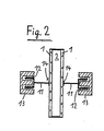
- FIGS. 1 and 2 Two exemplary embodiments of the invention are described in more detail with reference to FIGS. 1 and 2.
- Figures 1 and 2 each show a device for performing a method according to the invention.
- FIG. 1 shows an embodiment of the invention, the insulating glass unit being acoustically excited and the resonance frequencies of the vibrations of the system which are being recorded being recorded.
- Shown is a double-pane insulating glass with two identical panes 1 and an enclosed pane space 2.
- a large loudspeaker (bass loudspeaker) 3 is arranged symmetrically.
- the loudspeakers 3 are of identical construction and are excited in series by an amplifier 4 and a frequency generator 5 with sinusoidal oscillation. Switching from in-phase to out-of-phase excitation takes place by reversing the polarity of one of the two loudspeakers with switch 6.
- a simple capacitive displacement sensor is used to make the disc vibrations visible.
- Both transducers are each connected to a preamplifier 9, which supplies the plates 7, 8 with a bias voltage of approximately 20 V and receives and amplifies the charge shift as a voltage signal when the distance between the plates 7, 8 changes, via a high-resistance input.
- the output signals of the amplifiers 9 with regard to amplitude and phase position can be observed well on a conventional two-beam oscillograph 10.
- the measurement proceeds as follows: If initially nothing is known about the vibration behavior of the insulating glass unit, the insulating glass unit can be stimulated by tapping it with your finger. The system is thereby set into free damped oscillation, which can be tracked on the oscillograph 10. In this way, the fundamental phase oscillation develops. The frequency f 0 of the vibration is read. The speakers 3 are then excited in phase opposition and in the vicinity of the frequency f 0 the resonance frequency f R , ie the frequency at which the disks vibrate with maximum amplitude, is measured exactly. If the position transducers have not yet been adjusted, this can be done by: only one loudspeaker 3 is switched on in succession and the distances are set such that the same sensitivity, that is to say signals of the same strength, are present at both receiver branches.
- the phase relationship of the components can be checked: the phase difference between the two panes 1 is 180 °, between the two loudspeakers 3 also 180 °. Each loudspeaker 3 has a phase advance of 90 ° to the disk 1 adjacent to it.
- the Amrdnung shown in Fig. 1 corresponds essentially to a laboratory structure.
- the capacitive displacement sensor plates 7, 8
- optical or piezoelectric detectors can be used, which make adjustment unnecessary.
- the oscillograph 10 digitally displaying instruments for phase, frequency and amplitude of all four components (loudspeaker 3 and disks 1) can be used. Automation of the entire process with determination of the Resonance frequency, with control of the correct wave form and with on-line computer evaluation is easily possible with the state of the art.
- the resonance frequencies of a double-pane insulating glass unit with different filling gases for phase oscillation f R and phase oscillation f R are listed in the following table.
- the pane size is 60 x 60 cm
- the pane thickness is 4 mm
- the material values cp / c v and the temperature conductance ⁇ are also given:
- FIG. 2 shows a second device for carrying out a method according to the invention, which is based not on the measurement of the resonance frequency but on the measurement of the reference variable.
- Symmetrical electromagnetic vibration exciters (buttons 11, voice coils 12, permanent magnets 13) and measuring elements (piezoelectric selectors 14) are attached to both panes 1 of an insulating glass unit, for example by means of adhesives or suction elements.
- the insulating glass unit becomes forced vibrations outside the resonance frequencies by direct coupling with the exciter excited.
- the benchmark D or the energy consumption of the system is determined.
- the two panes 1 of the insulating glass unit are firmly connected to the electromagnetic vibration exciters (11, 12, 13) and can be set into oscillation in phase or in opposite phase with the aid of a sine generator (not shown) and an amplifier, similar to that in FIG. If a working frequency is chosen which is small compared to the resonance frequency of the system, then the phase difference between the exciter and the oscillator goes to zero and the reference variable D can be defined as a proportionality factor between the periodically exciting force K and the amplitude A, as in the stationary case:
- the amplitude A can be tracked using electrical or optical pickups as in the method described with reference to FIG. 1.
- the exciting force can be determined directly or by using a piezoelectric detector 14. It is also possible to measure the power consumption (alternating current and alternating voltage) of the two excitation coils 12 and to calibrate the coils 12 accordingly in force units.
- the benchmark is determined one after the other in the same-phase and in-phase vibration mode.
- the first case it is characterized by the restoring force of the system without gas compression, that is to say solely by the glass panes 1, in the second case by the significantly higher restoring force of the system with gas compression.
- the difference ⁇ D of the two measured values is therefore the standard quantity which is brought about by the compression of the gas cushion.
- ⁇ D can basically be used as a measure of the value sought of the filling gas can be used, according to the formula:
- the factor F is only dependent on geometric data such as the size of the slice or the distance between the slices and on the measuring frequency.
- the relationship with the disc size and spacing can be represented analytically or numerically.
- the dependence on the frequency arises from the influence of heat dissipation mentioned above and is determined experimentally by means of corresponding test series.
- the restoring force of the disks themselves can be eliminated by the in-phase comparison measurement, so that there is a relatively simple functional connection with the compressibility and the y- value of the gas.
- the frequency dependence of F mentioned due to the non-ideal adiabatic volume change can be used as a further refinement of the method. Since the frequency response of F is largely determined by the temperature conductance, measurements can be made at slightly different values Frequencies ⁇ and ⁇ can be determined independently of one another. The concentration of the filling gas can thus be specified even more precisely and reliably.
Landscapes
- Physics & Mathematics (AREA)
- Acoustics & Sound (AREA)
- Health & Medical Sciences (AREA)
- Life Sciences & Earth Sciences (AREA)
- Chemical & Material Sciences (AREA)
- Analytical Chemistry (AREA)
- Biochemistry (AREA)
- General Health & Medical Sciences (AREA)
- General Physics & Mathematics (AREA)
- Immunology (AREA)
- Pathology (AREA)
- Investigating Or Analysing Materials By Optical Means (AREA)
Applications Claiming Priority (2)
| Application Number | Priority Date | Filing Date | Title |
|---|---|---|---|
| DE3439216 | 1984-10-26 | ||
| DE19843439216 DE3439216C1 (de) | 1984-10-26 | 1984-10-26 | Bestimmung des Fuellgases von Isolierglaseinheiten |
Publications (1)
| Publication Number | Publication Date |
|---|---|
| EP0180068A2 true EP0180068A2 (fr) | 1986-05-07 |
Family
ID=6248811
Family Applications (1)
| Application Number | Title | Priority Date | Filing Date |
|---|---|---|---|
| EP85112708A Withdrawn EP0180068A2 (fr) | 1984-10-26 | 1985-10-08 | Détermination du gaz de remplissage d'unités en verre isolant |
Country Status (2)
| Country | Link |
|---|---|
| EP (1) | EP0180068A2 (fr) |
| DE (1) | DE3439216C1 (fr) |
Cited By (3)
| Publication number | Priority date | Publication date | Assignee | Title |
|---|---|---|---|---|
| EP0658765A1 (fr) * | 1993-12-13 | 1995-06-21 | Lenhardt Maschinenbau GmbH | Méthode et appareil pour déterminer la fin du remplacement de l'air par un gaz différent dans un vitrage isolant |
| RU2142131C1 (ru) * | 1998-05-27 | 1999-11-27 | Государственный научный центр "Институт физики высоких энергий" | Акустический газоанализатор |
| RU2335761C1 (ru) * | 2007-02-08 | 2008-10-10 | Валерий Андреевич Базыленко | Акустооптический индикатор критических концентраций опасных газов |
Families Citing this family (1)
| Publication number | Priority date | Publication date | Assignee | Title |
|---|---|---|---|---|
| DE19851569C2 (de) | 1998-11-09 | 2003-01-30 | Armin Schwab | Sensor zur Zustandsüberprüfung der Gasfüllung im Isolierraum einer Isolierglasscheibe und Isolierglasscheibe |
Family Cites Families (1)
| Publication number | Priority date | Publication date | Assignee | Title |
|---|---|---|---|---|
| DD130079A1 (de) * | 1977-03-01 | 1978-03-01 | Manfred Keil | Einrichtung zum pruefen von mehrscheibenglas |
-
1984
- 1984-10-26 DE DE19843439216 patent/DE3439216C1/de not_active Expired
-
1985
- 1985-10-08 EP EP85112708A patent/EP0180068A2/fr not_active Withdrawn
Cited By (3)
| Publication number | Priority date | Publication date | Assignee | Title |
|---|---|---|---|---|
| EP0658765A1 (fr) * | 1993-12-13 | 1995-06-21 | Lenhardt Maschinenbau GmbH | Méthode et appareil pour déterminer la fin du remplacement de l'air par un gaz différent dans un vitrage isolant |
| RU2142131C1 (ru) * | 1998-05-27 | 1999-11-27 | Государственный научный центр "Институт физики высоких энергий" | Акустический газоанализатор |
| RU2335761C1 (ru) * | 2007-02-08 | 2008-10-10 | Валерий Андреевич Базыленко | Акустооптический индикатор критических концентраций опасных газов |
Also Published As
| Publication number | Publication date |
|---|---|
| DE3439216C1 (de) | 1986-05-15 |
Similar Documents
| Publication | Publication Date | Title |
|---|---|---|
| EP0456787B1 (fr) | Detection selective de gaz par separation de champ et mesure de la vitesse du son: detection d'oxygene | |
| US2950436A (en) | Apparatus for controlling or checking the irregularity of a flow of textile or like materials | |
| DE102018127526A1 (de) | Vibronischer Multisensor | |
| DE1074882B (de) | Anordnung zur Bestimmung der mechanischen Konstanten eines nichtfesten Stoffes | |
| EP0365622A1 (fr) | Procede et appareil de mesure non-destructive des proprietes magnetiques d'un objet. | |
| CH657457A5 (de) | Pruefeinrichtung zur bestimmung von schwingungseigenschaften mindestens eines messwertaufnehmers. | |
| DE19644290C2 (de) | Sensorelement zur gleichzeitigen Messung von zwei verschiedenen Eigenschaften einer chemisch sensitiven Substanz in einem Fluid | |
| EP2021756A1 (fr) | Capteur mems dans le vide selon le principe de friction | |
| DE3439216C1 (de) | Bestimmung des Fuellgases von Isolierglaseinheiten | |
| DE19613274A1 (de) | Verfahren und Vorrichtung zur Bestimmung spezifischer Gas- oder Ionenkonzentrationen | |
| DE3707622A1 (de) | Verfahren und vorrichtung zum messen geringer gaskonzentrationen | |
| DE4040084A1 (de) | Beruehrungsloses abstandsmessgeraet | |
| DE2613528C3 (de) | Schwingkondensator | |
| DE2116782C3 (de) | Verfahren und Vorrichtung zur Bestimmung des Volumens pro Längeneinheit von fadenförmigen Erzeugnissen der Textilindustrie | |
| DE2144770C2 (de) | Einrichtung zum Bestimmen physikalischer Eigenschaften von gasförmigen, flüssigen oder pulverförmigen Stoffen | |
| DE4436813A1 (de) | Vorrichtung und Verfahren zur Bestimmung der Zusammensetzung von Gasmischungen | |
| DE19924369A1 (de) | Verfahren und Vorrichtung zur Überprüfung der Dichtheit von Senoren | |
| WO2002097984A1 (fr) | Element resonateur piezo-electrique du groupe ponctuel cristallographique 32 | |
| DE2633178C3 (fr) | ||
| EP0015368A1 (fr) | Dispositif de mesure de la pression d'air | |
| DE102004018506A1 (de) | Verfahren und Vorrichtung zur Herstellung einer Messvorrichtung zur Bestimmung und/oder Überwachung einer Prozessgröße und entsprechende Messvorrichtung | |
| DE3417826C2 (fr) | ||
| EP4446714B1 (fr) | Capteur de mesure de deux proprietes d'un gaz | |
| EP0183062B1 (fr) | Procédé et dispositif pour examiner le gaz de remplissage des carreaux de verre isolant | |
| DE3234584A1 (de) | Koerperschall-aufnehmer piezoelektrischer biegungs-aufnehmer |
Legal Events
| Date | Code | Title | Description |
|---|---|---|---|
| PUAI | Public reference made under article 153(3) epc to a published international application that has entered the european phase |
Free format text: ORIGINAL CODE: 0009012 |
|
| AK | Designated contracting states |
Kind code of ref document: A2 Designated state(s): AT BE CH DE FR GB IT LI NL SE |
|
| STAA | Information on the status of an ep patent application or granted ep patent |
Free format text: STATUS: THE APPLICATION IS DEEMED TO BE WITHDRAWN |
|
| 18D | Application deemed to be withdrawn |
Effective date: 19881101 |
|
| RIN1 | Information on inventor provided before grant (corrected) |
Inventor name: BOOS, RUDI Inventor name: SCHERBER, WERNER, DIPL.-PHYS. |