EP0180076A1 - Moyeu à vitesses multiples pour cycles - Google Patents
Moyeu à vitesses multiples pour cycles Download PDFInfo
- Publication number
- EP0180076A1 EP0180076A1 EP85112862A EP85112862A EP0180076A1 EP 0180076 A1 EP0180076 A1 EP 0180076A1 EP 85112862 A EP85112862 A EP 85112862A EP 85112862 A EP85112862 A EP 85112862A EP 0180076 A1 EP0180076 A1 EP 0180076A1
- Authority
- EP
- European Patent Office
- Prior art keywords
- gear
- coupling
- axially
- hub
- hub according
- Prior art date
- Legal status (The legal status is an assumption and is not a legal conclusion. Google has not performed a legal analysis and makes no representation as to the accuracy of the status listed.)
- Granted
Links
- 230000008878 coupling Effects 0.000 claims description 134
- 238000010168 coupling process Methods 0.000 claims description 134
- 238000005859 coupling reaction Methods 0.000 claims description 134
- 210000000078 claw Anatomy 0.000 claims description 38
- 230000006835 compression Effects 0.000 claims description 29
- 238000007906 compression Methods 0.000 claims description 29
- 230000009471 action Effects 0.000 claims description 13
- 238000006073 displacement reaction Methods 0.000 claims description 12
- 230000006870 function Effects 0.000 claims description 10
- 230000005540 biological transmission Effects 0.000 claims description 6
- 230000003993 interaction Effects 0.000 claims description 6
- 238000000034 method Methods 0.000 claims description 5
- 239000013641 positive control Substances 0.000 claims description 5
- 230000008569 process Effects 0.000 claims description 5
- 241001233037 catfish Species 0.000 claims description 4
- 230000002441 reversible effect Effects 0.000 claims description 4
- 230000000630 rising effect Effects 0.000 claims description 3
- 239000007822 coupling agent Substances 0.000 claims 2
- 210000004072 lung Anatomy 0.000 claims 1
- 230000013011 mating Effects 0.000 claims 1
- 238000010276 construction Methods 0.000 description 7
- 230000007246 mechanism Effects 0.000 description 7
- 230000008901 benefit Effects 0.000 description 4
- 230000007704 transition Effects 0.000 description 4
- 230000004323 axial length Effects 0.000 description 3
- 230000008859 change Effects 0.000 description 3
- 238000005096 rolling process Methods 0.000 description 3
- 230000036961 partial effect Effects 0.000 description 2
- 230000000284 resting effect Effects 0.000 description 2
- 241001295925 Gegenes Species 0.000 description 1
- 101000952234 Homo sapiens Sphingolipid delta(4)-desaturase DES1 Proteins 0.000 description 1
- 102100037416 Sphingolipid delta(4)-desaturase DES1 Human genes 0.000 description 1
- 230000015572 biosynthetic process Effects 0.000 description 1
- 238000006243 chemical reaction Methods 0.000 description 1
- 230000000994 depressogenic effect Effects 0.000 description 1
- 230000002349 favourable effect Effects 0.000 description 1
- 230000004048 modification Effects 0.000 description 1
- 238000012986 modification Methods 0.000 description 1
- 230000009993 protective function Effects 0.000 description 1
- 230000000717 retained effect Effects 0.000 description 1
- 230000007480 spreading Effects 0.000 description 1
Images








Classifications
-
- B—PERFORMING OPERATIONS; TRANSPORTING
- B62—LAND VEHICLES FOR TRAVELLING OTHERWISE THAN ON RAILS
- B62M—RIDER PROPULSION OF WHEELED VEHICLES OR SLEDGES; POWERED PROPULSION OF SLEDGES OR SINGLE-TRACK CYCLES; TRANSMISSIONS SPECIALLY ADAPTED FOR SUCH VEHICLES
- B62M11/00—Transmissions characterised by the use of interengaging toothed wheels or frictionally-engaging wheels
- B62M11/04—Transmissions characterised by the use of interengaging toothed wheels or frictionally-engaging wheels of changeable ratio
- B62M11/14—Transmissions characterised by the use of interengaging toothed wheels or frictionally-engaging wheels of changeable ratio with planetary gears
- B62M11/16—Transmissions characterised by the use of interengaging toothed wheels or frictionally-engaging wheels of changeable ratio with planetary gears built in, or adjacent to, the ground-wheel hub
Definitions
- the invention relates to a multi-speed hub for bicycles or the like, with a gear shift for more than three gears according to the preamble of claim 1.
- a 5-speed bicycle hub is already known, in which the planetary gear has a system of stepped planet gears and two sun gears which can be alternately fixed on the hub axle. Switching elements are provided on each side of the hollow-drilled hub axle to control this hub gear.
- This arrangement is complex and requires two separate switching elements for actuation by the user of the bicycle.
- Such a mode of operation for a multi-gear shift on the bicycle is cumbersome and requires a relatively high level of skill on the part of the bicycle user in order to quickly and appropriately set the respective gear stage for driving in a specific speed range.
- Such a hub gearshift with two switching elements is ultimately undesirable due to the unfavorable handling.
- Such an operating state can be extremely disruptive for the user of the bicycle and is not responsible for the operational safety of the bicycle.
- the object of the present invention is, inter alia, to create a hub with more than three gears for bicycles or the like while avoiding the above-described inconveniences.
- the aim is not only the highest level of operational safety and ease of use, but also a coaster brake device housed in the hub with constant braking readiness.
- a bicycle hub with more than three gears is achieved, all of which can be shifted from one axial side of the hub and with a single shifting element, the actuation of this multi-speed hub according to the invention being able to be carried out simply and without any special effort.
- the construction according to the invention makes it possible to arrange a coaster brake device with constant braking readiness in addition to the transmission for more than three gears.
- the invention is explained in more detail below with reference to an exemplary embodiment of a hub with more than 3 gears illustrated in the drawing figure 1.
- the drawing figure 1 shows a hub with five gears and with an integrated coaster brake device.
- the driver 3 which has a sprocket 3 'in the drive grooves 3a, is in turn rotatably supported by a ball race 23 on a fixed cone 4 screwed to the hub axle 5.
- a planet gear carrier 6 is rotatable on the hub axle 5, but is axially fixed.
- This planet gear carrier 6 has planet gears 8 mounted on bolts 7, which are designed as stepped planet gears 8a and 8b, which mesh both with a concentric ring gear 11 and with sun gears 9 and 10 arranged on the hub axle 5.
- 24a shows a variant for the construction according to Fig. 24,
- the sun gears 9 and 10 can be controlled by means of a thrust block 12 which slides in a slot 5b of the hub axle 5 against the tension of a compression spring 28 and can be actuated from the outside by a pull rod 12a via a pull chain 12b with a connecting part 12c.
- a coaxial compression spring 30 acts on the axially left-hand sun gear 9, the tension of which is also passed on to the sun gear 10 when the sun gear 9 is in contact with the latter.
- the actuator for the tie rod 12a with chain 12b and connector 12c for controlling the push block 12 is not shown here.
- the sun gears 9 and 10 which differ in their number of teeth, can alternately be coupled in a rotationally fixed manner, the sun gear 9 with axial coupling claws 9a being able to be coupled by axial displacement with corresponding claws 13a of a sliding sleeve 13, which in turn is arranged on the hub axle 5 in a rotationally fixed manner by means of axle claws 5a, however is axially displaceable.
- the sun gear 10 which is larger in the number of teeth, is connected in a rotationally fixed manner by means of radial coupling elements 10a to the sliding sleeve 13 which coaxially accommodates the sun gear 10, but is axially displaceable by itself.
- the sun gear 10 meshes with a planetary gear 8b with a smaller number of teeth, while the sun gear 9, which is loosely rotatable on the hub axle 5, meshes with a planetary gear 8a with a larger number of teeth.
- Compression spring 30 acts on both sun gears 9 and 10 from the left axially.
- a coupling bush 14 can be rotated coaxially to the sliding sleeve 13 and can be axially displaced against spring tension, as will be described below.
- the coupling bush 14 On its outer circumference, the coupling bush 14 is provided with axially separated toothings 14a and 14b, the axially left-hand toothing 14a being additionally set up for the rotationally fixed reception of a laterally arranged drive plate 15.
- the axially right toothing 14b of the coupling bush 14 is constantly in engagement with the axially long internal toothing 3b of the driver 3.
- a brake cone 17 is axially displaceably arranged on an adjusting thread 6a, which is at the same time designed as a carrier for a set of drive pawls 18, the latter being under tension of a ring spring, constantly engaging in an internal locking mechanism la of the hub sleeve 1 .
- the above-mentioned ring gear 11 carries on the shoulder part provided with the internal toothing 11b a further set of spring-loaded drive locking mechanisms 19, which, depending on the position of the axially displaceable ring gear 11, can engage in an internal locking mechanism 1b of the hub sleeve 1, as is shown, for example, in FIG. 1, or can also be disengaged in the hub sleeve 1 by means of a conical surface 1c.
- the above-mentioned brake cone 17 is in turn under the action of a friction spring 20, in catfish to be described when the driver 3 rotates backwards on the setting thread of the planetary gear shaft axially to the left and thereby spreads a brake jacket 24/25, which in turn is provided on a brake lever 27 Lever cone 2 is held in a rotationally fixed manner. By spreading the brake jacket 24 in the hub sleeve 1, this is braked reliably.
- the aforementioned thrust block 12 is, as can be clearly seen in FIG. 1, under tension from a coaxial compression spring 28 which is supported on the fixed cone 4 on the hub axle 5 and can be located within the slot 5b in the hub axle 5 by means of the tie rod 12a with a connected pull chain 12b and attachment part 12c are shifted axially to the right, in order to achieve different gearshift stages, as will be described later.
- the gear switch connected to the attachment part 12c by means of a shift cable is not shown here.
- the multi-speed hub shown for example, is shown in the 5th gear position (high overdrive).
- the thrust block 12 loaded by the spring 28 is located in the axially left position within the hub axle slot 5b.
- the sliding sleeve 13 is standing under the action of a coaxial compression spring 34, in the axially left end position, which is determined by the axis claws 5a which serve to hold the sliding sleeve 13 in a rotationally fixed manner.
- the sliding sleeve 13 is surrounded by an intermediate sleeve 29, which is penetrated by the push block 12 without play, as can be clearly seen in FIG.
- This intermediate sleeve 29 forms the axial stop to the right for the sun gear 10, which is acted upon on the left side by the sun gear 9 under the action of the compression spring 30.
- the sun gear 10 is connected in a rotationally fixed manner by means of its radial coupling elements 10a to the sliding sleeve 13 via coupling elements 13b directed radially outwards.
- the sun gear 10 is indirectly non-rotatably on the hub axle 5, while the sun gear 9 on the hub axle 5 can be freely rotated in this gearshift position because, owing to the position on the extreme left, there is no coupling connection with the axial elements 9a of the sun gear 9 with the corresponding coupling toothing 13a Sliding sleeve 13 is made.
- the coupling bush 14 is in engagement with its toothing 14b in the driver 3 / 3b, while the toothing 14a is in operative connection with the claws 6b of the planetary gear carrier 6 via the driving disk 15, which is fixedly attached to the non-rotatable driving disk.
- the planet gear carrier 6 drives the planet gears 8 via its bearing bolts 7, of which the step gear 8b meshes with the sun gear 10, which is fixed in rotation in the catfish described above, on the one hand and with the ring gear toothing 11a on the other hand.
- the ring gear 11 is connected via the drive pawl set 19 to the internal locking mechanism 1b in the hub sleeve 1.
- the thrust block 12 is pulled even more axially to the right by means of the switching device, so that the ring gear 11 is displaced so far against the tension of the compression spring 36 via the coupling bushing 14 that the pawls 19 on the ring gear the switching cone surface lc of the hub sleeve 1 are disengaged.
- the axial movement of the thrust block relative to the sliding sleeve 13 is made possible by an axially long slot 13c.
- the sliding sleeve 13 has remained in the axial position shown in FIG. 1, and the rotationally fixed coupling of the sun gear 9 with the sliding sleeve 13 mentioned in connection with the 4th gear shift position remains unchanged. Accordingly, the sun gear 10 is rotatable on the sliding sleeve 13.
- the embodiment of a multi-speed hub according to the invention with more than three gears has, in particular, an arrangement of concentric sleeve elements, the relative shift of which against spring tension causes the gear shift.
- this sleeve arrangement includes the intermediate sleeve 29 which is displaceable on the sliding sleeve 13 and which is controlled directly by the thrust block 12, on the other hand axially control the sun gears 9 and 10, and finally the radially inner sliding sleeve 13 itself , which is directly displaceable on the hub axle 5 and is designed in accordance with the axial position for alternating rotationally fixed coupling with the sun gear 9 or sun gear 10.
- a system of deflection slopes is provided either on the sliding sleeve 13 or also on one of the sun gears 9 or 10, preferably on the small sun gear 9.
- the concentric compression springs 28 and 34 present in the sleeve arrangement can be appropriately spaced from one another by means of corresponding end caps with axial length.
- the aim of the elements of a multi-speed hub described below is to create a hub which is equipped with more than three gears and has a coaster brake device and which offers the highest level of operational safety combined with constant braking readiness.
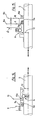
- FIGS. 2 to 11 show measures to prevent idling, namely by means of a forced control in the area of the sun gears, special configurations and shapes of the coupling elements being taken.
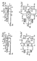
- FIGS. 2a and 2a ' show a hub axle 5 provided with clutch teeth.
- the clutch teeth 5a have parallel flanks for engagement.
- one of the two sun wheels 9 and 10 which can be displaced on the hub axle.
- the clutch profile of one of the two sun wheels - the smaller one in the figure Wheel - Is designed as an axial extension 9a of the sun gear body and equipped with inclined surfaces 9b.
- the shift position is reached in which the sun gear 10 is effective as part of the planetary gear and the sun gear 9 rotates freely.
- the axial length of the coupling teeth 5a is at most as large as the axial length of the bevels 9b, so that the coupling teeth 5a can in no case be simultaneously in engagement with the straight flanks 9a and the straight flanks 10a.
- the sun gear 10 can follow to the left under the action of the softer spring 50, so that the flanks 10a then come into engagement with the clutch teeth 5a, so that now again one of the sun gears 9, 10, namely the sun gear 10, on the hub axle 5 is secured against rotation and thus the planetary gear is torque-transmitting, that is, both a drive torque and in particular a braking torque can be transmitted.
- one of the sun gears 9, 10 is always effective as part of the planetary transmission, that is to say always a drive torque and in particular a braking torque can also be transmitted.
- Figures 2b and 2b 'to provide a performance similar to the Fl- g u ren 2a and 2a' are, however, here are the inclined surfaces, which are each one of the two sun gears 9 and 10 cause the transition area the inevitable Reject - In the picture of the smaller Sun gear 9 - arranged on the coupling teeth 5a of a component which is fixedly connected to the hub axle 5 and annularly surrounds the hub axle.
- FIGS. 2a, 2a 'and 2b, 2b' have the advantage that only a single coupling toothing 5a is required on the hub axle 5.
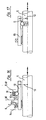
- FIGS. 3 and 3a show an arrangement in which the two sun gears 9 and 10 are shifted to change gear between the two clutch gears 5a of the hub axle 5, and each sun gear 9 and 10 is brought into engagement with this clutch with its coupling gears 9a and 10a provided for this purpose can be. Avoiding idling In the transition area between the individual gear shift stages, switching slopes are again formed, which are formed on the coupling profile of one of the sun gears 9 or 10 - in the picture on the smaller sun gear 9, 9b.
- FIGS. 4 and 4a give an exemplary embodiment, the function of which is similar to the arrangement described in FIGS. 3 and 3a.
- the deflecting surfaces 5b for forcibly displacing the sun gears 9 and 10 are arranged on one of the two coupling gears 5a, 5a 'of the hub axle 5 - in the picture on the gearing 5b provided for the smaller sun gear 9 .
- FIGS. 3, 3a and 4, 4a have the advantage that each of the axle gears 5a can be specifically coordinated with the respective sun gear 9 or 10 for optimum coupling behavior.
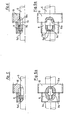
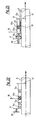
- Figures 5 and 5a show an embodiment, bel the two sun gears 9 and 10 are fixed axially in a manner not shown.
- an axially displaceable coupling element arranged axially between the sun gears 9 and 10 is brought into engagement with the inner profile of the sun gear 9 or 10 to be switched on in each case.
- FIG. 6 shows an embodiment which is largely identical to that according to FIGS. 5 and 5a. Only the inclined surfaces, which bring about the forced engagement, are now arranged on the coupling element 5a ', 5b instead of on the sun gears and point to one of the two sun gears 9 and 10.
- FIGs 7 and 8 each show a variant with axially fixed sun gears 9 and 10.
- the clutch elements 5a 'arranged outside the sun gear package 9/10 are brought into engagement with one or the other sun gear clutch profile 9a or 10a.
- the compression spring 51 again takes over the function of the compression spring 51 from the embodiment of FIGS. 3 and 3a.
- the switching slopes 9b for forced reversing are arranged on the inner profile of one of the two sun gears 9 in the embodiment according to FIG. 7, but on one of the two coupling elements 5a ', 5b in the embodiment according to FIG.
- FIG. 9 shows an embodiment in which, in the area between the sun gears 9 and 10, a coupling toothing 13a is provided on a rotationally fixed sliding sleeve 13 for alternately holding one of the two sun gears 9 and 10, respectively.
- the sun gears 9 and 10 are axially fixed.
- the coupling teeth of one of the sun gears 9 or 10 are provided with deflection slopes 9b, as can be seen in FIG. 9a.
- FIGS. 10 and 11 each show an embodiment in which the axially fixed sun gears 9 and 10 are mounted on a rotationally fixed sliding sleeve 13, this sliding sleeve 13 being arranged on the hub axle 5 in a rotationally fixed but axially displaceable manner.
- the clutch teeth of the sliding sleeve 13 for engaging the inner profiles 9a and 10a of the sun gears 9 and 10 is provided axially between the sun gears in FIG. 10, while in FIG. 11 the clutch teeth 13a are provided axially outside the sun gears 9 and 10 on the sliding sleeve 13 .
- FIGS. 12 to 21 show systems which serve to switch the two sun gears and at the same time prevent shift positions from being engaged between the gears, which can result in idling.
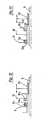
- FIG. 12 shows a deflection lever A which is actuated by means of a push-pull shift cable B and has a detent D on a curve C which only permits those switching positions which, in the gear hub, provide the functionally reliable overlap ratios between the alternating sun gears to be coupled and the hub axle.
- FIG. 13 shows a switching pin E, which is locked to the hub axle 5 by means of a series of locking notches, which can interact, for example, with a locking ball F.
- Switching pin E is actuated via a push-pull shift cable B, the detent F does not permit any intermediate positions that interfere with the function.
- the detent can also be made on a component attached to the axle.
- FIGS. 14 and 15 show two variants, in each of which one of the sun gears 9 and 10, which are axially displaceable by themselves, can be locked either with the hub axle 5 or the planet gear carrier 6 by means of locking elements G or H.
- FIGS. 16, 17 and 18 represent shift systems in which a sliding sleeve 13 which is non-rotatable but axially displaceable with the hub axle 5 is locked.
- this latching takes place between the sliding sleeve 13 and one of the axially fixed sun gears 9 or 10.
- FIGS. 19 and 20 show variants in which an auxiliary sleeve I, which is locked to the hub axle 5 or to the planet gear carrier 6, is used to switch the sun gears 9 and 10, which are displaceably mounted on the hub axle 5.
- FIG. 21 shows an arrangement in which the thrust block 12 itself engages in an axially fixed spring element K for specifying the correct switching paths.
- the sun gears 9 and 10 are arranged axially displaceable to the hub axis 5, which in turn has clutch teeth 5a for cooperation with the clutch surfaces 9a and 10a.
- the thrust block 12 can act on a sliding sleeve 13, an auxiliary sleeve I or, as shown, directly on the sun gears 9 and 10. - This arrangement, like all the other aforementioned systems, is also operated via a push-pull shift cable B.
- FIGS. 22 to 26 show circuit systems which have to be switched in only one direction and which allow a hub structure with a total of only one shift cable or one shift pin as a control element.
- the thrust block 12 is shifted axially to the right that the larger sun gear 10 is uncoupled by the force of the indicated spring 30 and at the same time the smaller sun gear 9 is coupled into the axially left-hand axle teeth 5a.
- FIG. 23 shows another arrangement which, in addition to the axially displaceable sun gears 9 and 10, has a sliding sleeve 13 equipped with two coupling teeth 13a for engagement in the sun gears 9 and 10 and an inner profile 13 'for the rotationally fixed coupling with the hub axle 5.
- One of the sun gears - in the picture the smaller sun gear 9 - is mounted on the hub axle 5, the other sun gear 10 is mounted on the sliding sleeve 13.
- the indicated spring 30 brings the small sun gear 9 to the right into active connection with the left coupling toothing 13a of the sliding sleeve 13 and releases the coupling connection between the large sun gear 10 and the sliding sleeve 13.
- the position of the sun gears 9 and 10 remains unchanged.
- figure 24 is shown a structure which is connected to a rotatably fixed to the hub axle 5, but axially displaceable sliding sleeve 13 with two clutch teeth 13a for engagement in the K upplungsprofile 9a and 10a of the sun gears 9 and 10 is provided.
- this sliding sleeve 13 the two sun gears 9 and 10 are rotatable but axially fixed in the planet carrier.
- the clutch teeth 5a of the hub axle 5, the clutch teeth 13a of the sliding sleeve 13 or the inner profiles 9a, 10a of the Sun gears 9 and 10 can be equipped with inclined surfaces for the positive control of the clutch engagement.
- precautions such as those described in connection with FIG. 9 with regard to the sliding sleeve 13 can, in combination with the arrangements according to FIGS. 22, 23 and 24, prevent idling between the gears.
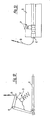
- FIGS. 25 and 26 each show a system in which a reversal of the direction of movement of a special control sleeve S is achieved by a lever K or also by a rising tooth system.
- the small sun gear 9 is coupled into the axle toothing 5 a by the indicated spring 30 and at the same time the connection between the hub axle 5 and the large sun gear 10 is released.
- the sliding sleeve 13 meets the rocker arm K which pushes the control sleeve S axially to the left and thus also the large sun gear 10, which thus engages again in the axle teeth 5a while the sun gear 9 - against the spring 30 - is pushed out of the clutch assembly with the axle teeth 5a.
- a push block or a sliding clutch wheel can also serve as the switching element for the rocker arm K.
- FIG. 26 The mode of operation of FIG. 26 can be imagined as follows: if the sliding sleeve 13 'runs to the right against the ring T surrounding the hub axis, the non-rotatable sleeve 13' causes the sleeve 13 'to couple via a first pair of not shown thread-like cooperating cams and the ring T a rotation of the ring T about the hub axis 5. Between the control sleeve S and the ring T is a further pair of thread-like interacting cams attached, which cause a displacement of the control sleeve S to the left in the previously described rotation of the ring T.
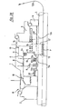
- FIGS. 27 and 28 schematically show exemplary embodiments for the construction of a shift hub with more than three gears and a coaster brake device in which the previously described special components can be used expediently.
- FIG. 28 shows a further embodiment of a 5-speed coaster brake hub in the 5th gear switch position, in which the sun gears 9 and 10 are mounted on a rotatably mounted sliding sleeve 13, but are axially fixed to the planet gear carrier.
- the clutch 14 between the planet carrier 6, the ring gear 11 and the driver 3 is also known from 3-speed hubs.
- the gear change in this hub also only takes place in one direction and in the following way: by pulling the single shift cable 12b, both thrust blocks 12 and 12 'and under the action of the spring 30 the sliding sleeve 13 are shifted axially to the right until the large one Sun gear 10 disengaged on the sliding sleeve 13 and the small sun gear 9 is engaged by means of the elements 9a / 13a.
- the brake device R which can be actuated by turning the driver 3 backwards, is already known in its simple construction from 3-speed gear hubs, so that a separate description of the brake device is not necessary here.
- the exemplary embodiments of a 5-speed hub according to FIGS. 1, 27 and 28 can also be designed as idle hubs by eliminating the braking device R, the advantage of the hub construction being that it is always ready to drive, even in shift positions between the gear shift stages, Im remains intact.
- FIG. 24a shows a structure in which the two sun gears 9 and 10 are rotatable on the hub axle 5, but are axially fixed.
- two axially displaceable, torsionally fixed coupling elements 13 and 13a are arranged in such a way that one of the sun gears 9 and 10 respectively corresponds by shifting, for example by means of thrust blocks 12 and 12a, which are axially displaceable and interconnected in the hub axle the assigned gear shift stage on the hub axle 5 can be fixed with one of the coupling elements 13 or 13a.
- the switching operation takes place only in an axial direction.
- FIgur 24a shows the structure in the 5th gear position.
- the thrust block system 12 / 12a is pulled axially to the right, so that the sun gear 10 is released from the clutch surface 13, while the sun gear 9 is non-rotatably coupled to the hub axle 5 by means of the clutch surface 13a.
- This clutch position also exists in the not yet mentioned 3rd and 2nd gear shift positions. -
- the thrust block system 12 / 12a is moved in the same axial direction in such a way that the sun gear 9 with its coupling surface 9a is released by the coupling element 13a, whereas the sun gear 10 is now coupled with its coupling surface 10a by means of the coupling element 13a and thus Is firmly connected to the hub axle 5.
- the clutch element 13 which has been effective in the gear shift position shown is now axially away from the sun gear 10 and has no function with regard to a clutch connection.
- the function sequence results in that first the large sun gear 10, then the small sun gear 9 and finally the large sun gear 10 are held in a rotationally fixed manner.
- This can be done by the fact that one or the other sun gear is directly connected to the hub axle 5 in a rotationally fixed manner by means of the thrust block arrangement mentioned, it is also possible to arrange a so-called sliding sleeve 13 on the hub axle 5 in a rotationally fixed manner, with which then the sun gears in the above described sequence of functions are alternately connected in a rotationally fixed manner, which results in the corresponding engagement conditions for the system of stepped planet gears, not shown here, with which the different gear shift stages are achieved in the hub gear.
- the coupling surfaces on the sun gears and on the coupling means serving for fixing are not provided with parallel flanks, but rather are provided with undercut coupling surfaces, such that e.g. a so-called dovetail shape is formed.
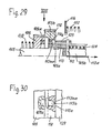
- FIG. 29 shows a schematic representation of the design of the sun gears 109 and 110 together with the coupling means, which serve to fix one of the sun gears 109 and 110 in a rotationally fixed manner on the hub axle 105.
- An embodiment as shown in FIG. 29 could be used in the construction according to FIG. 1.
- Fig. 29 corresponds to the position of the 5th gear (high overdrive) and to that extent of Fig. L. 29 is sunbathing wheel 110 engages with the straight coupling claws 113b of the sliding sleeve 113 through its internal toothing 110a, while the sliding sleeve 113 is fixed in a rotationally fixed manner on the hub axle 105 by the coupling claws 105a.
- the sun gear 109 is freely rotatable on the hub axle 105. If it is desired to switch from the 5th gear (large overdrive) shown in FIG.
- the pushing block 112a and with it the intermediate sleeve 129 against the action of the stronger helical compression spring is made by means of the pull rope 112a 128 shifted to the right so that under the action of the helical compression spring 130 the two sun gears 109 and 110 of the intermediate sleeve 129 can follow to the right until the sun gear 110 comes to a stop on the disk 116.
- the internal toothing 110a disengages from the clutch claws 113b and the clutch toothing 109a engages with the clutch claws 113b.
- the case may occur again that the internal toothing 110a does not have sufficient axial overlap with the straight sections of the coupling claw 113b. If, in the course of time, the case occurs due to deformation that the sun gear 110 is no longer rotationally fixed to the coupling claws 113b, the internal toothing 110a comes into engagement again with the inclined surfaces 113ba. The result is that the sun gear 110 is shifted to the right again and the sun gear 109 with its internal teeth 109a can now engage the clutch claws 113b again. This also ensures in this situation that one of the sun gears 109, 110 is fixed in a rotationally fixed manner at any moment and can thus be an effective reaction element of the planetary gear.
- the inclined surfaces 113ba can also fulfill their protective function when shifting from 2nd to 1st gear (see description of FIG. 1).
- the sun gears 109 and 110 are then in contact with the disk 116 and the sun gear 109 is coupled to the sliding sleeve 113. If the sliding sleeve 113 is now pulled further to the right as a result of the changeover, the clutch claws 113b again come into engagement with the internal toothing 110a of the sun gear 110. If the sliding sleeve 113 is not displaced to the right to ensure proper engagement of the clutch claw 113b with the internal toothing 110a, the internal toothing 110a engages with the inclined surfaces 113ba and the sun gear 110 is shifted further to the right.
Landscapes
- Engineering & Computer Science (AREA)
- Chemical & Material Sciences (AREA)
- Combustion & Propulsion (AREA)
- Transportation (AREA)
- Mechanical Engineering (AREA)
- Structure Of Transmissions (AREA)
- Retarders (AREA)
- Transmission Devices (AREA)
Priority Applications (2)
| Application Number | Priority Date | Filing Date | Title |
|---|---|---|---|
| EP91108264A EP0446966B1 (fr) | 1984-11-02 | 1985-10-10 | Corps de moyeu de transmission à plusieurs rapports |
| AT85112862T ATE74087T1 (de) | 1984-11-02 | 1985-10-10 | Mehrgangnabe fuer fahrraeder oder dergleichen. |
Applications Claiming Priority (2)
| Application Number | Priority Date | Filing Date | Title |
|---|---|---|---|
| DE3440067 | 1984-11-02 | ||
| DE3440067A DE3440067A1 (de) | 1984-11-02 | 1984-11-02 | Mehrgangnabe fuer fahrraeder oder dergleichen |
Related Child Applications (2)
| Application Number | Title | Priority Date | Filing Date |
|---|---|---|---|
| EP91108264A Division EP0446966B1 (fr) | 1984-11-02 | 1985-10-10 | Corps de moyeu de transmission à plusieurs rapports |
| EP91108264.2 Division-Into | 1991-05-22 |
Publications (2)
| Publication Number | Publication Date |
|---|---|
| EP0180076A1 true EP0180076A1 (fr) | 1986-05-07 |
| EP0180076B1 EP0180076B1 (fr) | 1992-03-25 |
Family
ID=6249328
Family Applications (2)
| Application Number | Title | Priority Date | Filing Date |
|---|---|---|---|
| EP85112862A Expired - Lifetime EP0180076B1 (fr) | 1984-11-02 | 1985-10-10 | Moyeu à vitesses multiples pour cycles |
| EP91108264A Expired - Lifetime EP0446966B1 (fr) | 1984-11-02 | 1985-10-10 | Corps de moyeu de transmission à plusieurs rapports |
Family Applications After (1)
| Application Number | Title | Priority Date | Filing Date |
|---|---|---|---|
| EP91108264A Expired - Lifetime EP0446966B1 (fr) | 1984-11-02 | 1985-10-10 | Corps de moyeu de transmission à plusieurs rapports |
Country Status (4)
| Country | Link |
|---|---|
| US (2) | US4721013A (fr) |
| EP (2) | EP0180076B1 (fr) |
| AT (2) | ATE109090T1 (fr) |
| DE (3) | DE3440067A1 (fr) |
Cited By (3)
| Publication number | Priority date | Publication date | Assignee | Title |
|---|---|---|---|---|
| WO1994020358A3 (fr) * | 1993-03-02 | 1994-10-13 | Sturmey Archer Ltd | Moyeu de bicyclette a engrenages de changement de vitesse epicycloidaux |
| CN116767415A (zh) * | 2022-03-16 | 2023-09-19 | 智盟能源股份有限公司 | 弹性离合变速机构 |
| EP4246012A1 (fr) * | 2022-03-16 | 2023-09-20 | ChargeON Corp. | Mécanisme de transmission à embrayage flexible |
Families Citing this family (39)
| Publication number | Priority date | Publication date | Assignee | Title |
|---|---|---|---|---|
| DE3829691A1 (de) * | 1988-09-01 | 1990-03-15 | Fichtel & Sachs Ag | Mehrgang-nabe |
| US4926714A (en) * | 1988-09-21 | 1990-05-22 | Louis Bailey | Gear selector for bicycle hub transmission |
| DE3930374A1 (de) * | 1988-10-10 | 1990-04-12 | Fichtel & Sachs Ag | Mehrgang-antriebsnabe mit mehr als drei gaengen |
| DE3834431A1 (de) * | 1988-10-10 | 1990-04-12 | Fichtel & Sachs Ag | Mehrgang-nabe |
| JP2930315B2 (ja) * | 1989-02-17 | 1999-08-03 | 株式会社シマノ | 自転車用内装変速機 |
| JP3184230B2 (ja) * | 1990-12-28 | 2001-07-09 | 株式会社シマノ | 内装変速機 |
| DE69202657D1 (de) * | 1991-09-09 | 1995-06-29 | Shimano Kk | Selbstständige Fahrradgangschaltung. |
| DE4203509A1 (de) * | 1992-02-07 | 1993-08-12 | Fichtel & Sachs Ag | Mehrgang-antriebsnabe fuer fahrraeder |
| DE4342347C1 (de) * | 1993-12-11 | 1995-02-09 | Fichtel & Sachs Ag | Mehrgangnabe für Fahrräder |
| GB9409844D0 (en) * | 1994-05-17 | 1994-07-06 | Sturmey Archer Ltd | An epicyclic change gear system |
| JP2968204B2 (ja) * | 1996-03-15 | 1999-10-25 | 株式会社シマノ | 逆転ブレーキ装置付き内装ハブ |
| DE19618636A1 (de) | 1996-05-09 | 1997-11-13 | Fichtel & Sachs Ag | Mehrgangnabe mit Rücktrittbremse für Fahrräder |
| US6199884B1 (en) | 1996-12-23 | 2001-03-13 | 7444353 Alberta Ltd. | Helical drive bicycle |
| US6241565B1 (en) | 1996-12-23 | 2001-06-05 | Helixsphere Technologies, Inc. | Helical drive human powered boat |
| US5855530A (en) * | 1997-07-30 | 1999-01-05 | Industrial Technology Research Institute | Speed-changing transmission hub for a bicycle |
| US5863270A (en) * | 1997-09-15 | 1999-01-26 | Industrial Technology Research Institute | Self-contained change speed apparatus for use on a bicycle |
| DE19822647B4 (de) * | 1998-05-20 | 2007-03-01 | Sram Deutschland Gmbh | Drehmomentübertragungselement für eine Mehrgangnabe für ein Fahrrad |
| DE19828829B4 (de) * | 1998-06-27 | 2004-08-05 | Kun Teng Industry Co., Ltd., Ta-Ya Hsiang | Fünfgangnabe |
| CN1085600C (zh) * | 1998-11-27 | 2002-05-29 | 昆藤工业股份有限公司 | 自行车内五速花毂 |
| US6039671A (en) * | 1999-02-09 | 2000-03-21 | Kun Teng Industry Co., Ltd. | Multi-speed drive hub for a bicycle |
| US6325739B1 (en) * | 1999-12-29 | 2001-12-04 | Shimano, Inc. | Bicycle hub transmission with a mechanism for stopping rotation of one or more sun gears relative to another member |
| US6607465B1 (en) | 2000-03-10 | 2003-08-19 | Shimano, Inc. | Bicycle hub transmission with a guiding member for a sun gear |
| US6368243B1 (en) | 2000-06-22 | 2002-04-09 | Liu Jen-Chih | Bike inner derailleur |
| DE10030941A1 (de) * | 2000-06-24 | 2002-01-03 | Sram De Gmbh | Mehrgangschaltnabe |
| DE10030959A1 (de) * | 2000-06-24 | 2002-01-03 | Sram De Gmbh | Mehrgangschaltnabe |
| EP1172291A1 (fr) * | 2000-07-11 | 2002-01-16 | Jen-Chih Liu | Frein avec deux moyens d'actionnement, intégré dans un moyeu à vitesses multiples pour véhicules à deux roues |
| DE10134842A1 (de) * | 2001-07-17 | 2003-02-06 | Sram De Gmbh | Lastschaltbare Mehrgangnabe |
| DE602007002549D1 (de) * | 2007-03-12 | 2009-11-05 | Shimano Kk | Nabenschaltung für ein Fahrrad |
| US8152189B2 (en) | 2007-08-27 | 2012-04-10 | Cannondale Bicycle Corporation | Bicycle frame and drive link case therefore |
| US8074530B2 (en) * | 2009-04-10 | 2011-12-13 | Shimano Inc. | Hub transmission assembly |
| EP2744699A1 (fr) * | 2011-08-17 | 2014-06-25 | Synergy Biosurgical AG | Dispositif destiné à la propulsion et au freinage excentrique d'un véhicule |
| US10239581B2 (en) | 2011-08-26 | 2019-03-26 | Gevenalle, Inc | Bicycle brake and shift lever assembly |
| US11022200B2 (en) | 2014-06-06 | 2021-06-01 | Delbert Tesar | Simplified parallel eccentric rotary actuator |
| US11166864B2 (en) | 2016-12-06 | 2021-11-09 | Delbert Tesar | Actuators for patient mobility devices, patient healthcare devices and human prosthetics |
| WO2018114613A1 (fr) | 2016-12-22 | 2018-06-28 | Gfpi S.A. | Mouvement pour piece d'horlogerie |
| DE102019205754B4 (de) * | 2019-04-23 | 2024-04-25 | Zf Friedrichshafen Ag | Schaltanordnung und Planetengetriebe sowie Kraftfahrzeug |
| US12065215B1 (en) * | 2023-02-03 | 2024-08-20 | New Kailung Gear Co., Ltd | Control device of internal speed change device of wheel hub for indirect clutching operation |
| TWI867948B (zh) * | 2024-01-24 | 2024-12-21 | 波壯科技股份有限公司 | 電動輔助腳踏車的內變速系統 |
| EP4700256A1 (fr) * | 2024-08-23 | 2026-02-25 | Volvo Truck Corporation | Transmission pour véhicule |
Citations (7)
| Publication number | Priority date | Publication date | Assignee | Title |
|---|---|---|---|---|
| FR439639A (fr) * | 1911-02-03 | 1912-06-19 | Schweinfurter Pracisions Kugel | Changement de vitesse à engrenages planétaires |
| US1490644A (en) * | 1922-07-10 | 1924-04-15 | Sturmey John James Henry | Five-speed gear for bicycles and machinery |
| GB473205A (en) * | 1936-04-09 | 1937-10-08 | Sturmey Archer Gears Ltd | Improvements in variable speed gear for velocipedes |
| FR914176A (fr) * | 1940-04-20 | 1946-10-01 | Sturmey Archer Gears Ltd | Mécanisme de changement de vitesse épicycloïdal |
| DE2337725A1 (de) * | 1973-07-25 | 1975-02-06 | Fichtel & Sachs Ag | Mehrgangnabe mit von der schaltstellung des antriebes unbeeinflusster bremsfunktion und mit schraegflaechen versehener schaltkupplung |
| DE2458871A1 (de) * | 1973-12-15 | 1975-06-19 | Raleigh Industries Ltd | Planetengetriebe-mehrgangnabe |
| DE2514418A1 (de) * | 1975-04-02 | 1976-10-21 | Fichtel & Sachs Ag | Mehrganguebersetzungsnabe fuer fahrraeder oder dergleichen |
Family Cites Families (13)
| Publication number | Priority date | Publication date | Assignee | Title |
|---|---|---|---|---|
| BE511864A (fr) * | ||||
| GB519945A (en) * | 1938-10-07 | 1940-04-10 | Sturmey Archer Gears Ltd | Improvements in or relating to epicyclic variable speed gearing |
| US2301852A (en) * | 1940-04-20 | 1942-11-10 | Sturmey Archer Gears Ltd | Epicyclic variable speed gearing |
| GB541332A (en) * | 1940-04-20 | 1941-11-24 | Sturmey Archer Gears Ltd | Improvements relating to epi-cyclic variable speed gearing |
| FI24771A (fi) * | 1947-07-12 | 1950-12-11 | Sturmey Archer Gears Brown W | Planetväxel med variabelt utväxlingsförhållande |
| FI24772A (fi) * | 1947-08-11 | 1950-12-11 | Sturmey Archer Gears Ltd Brown | Planetväxel |
| DE1505933B1 (de) * | 1961-05-05 | 1969-09-04 | Fichtel & Sachs Ag | Freilaufnabe fuer Fahrraeder,Motorraeder od.dgl. |
| BE628560A (fr) * | 1962-03-29 | |||
| DE2159770C2 (de) * | 1971-12-02 | 1983-03-03 | Fichtel & Sachs Ag, 8720 Schweinfurt | Mehrgang-Getriebenabe |
| DE2209535C2 (de) * | 1972-02-29 | 1974-01-17 | Fichtel & Sachs Ag, 8720 Schweinfurt | Mehrgangübersetzungsnabe mit Rücktrittbremse |
| US3973451A (en) * | 1974-12-06 | 1976-08-10 | Shimano Industrial Company, Limited | Five speed transmission hub for bicycles |
| US4065984A (en) * | 1975-01-25 | 1978-01-03 | Xenoah, Co. | Internally accommodated speed change mechanism applicable to a bicycle |
| US4147244A (en) * | 1976-11-27 | 1979-04-03 | Shimano Industrial Company Limited | Multi-speed transmission hub |
-
1984
- 1984-11-02 DE DE3440067A patent/DE3440067A1/de not_active Ceased
-
1985
- 1985-10-10 AT AT91108264T patent/ATE109090T1/de not_active IP Right Cessation
- 1985-10-10 DE DE8585112862T patent/DE3585718D1/de not_active Expired - Lifetime
- 1985-10-10 EP EP85112862A patent/EP0180076B1/fr not_active Expired - Lifetime
- 1985-10-10 EP EP91108264A patent/EP0446966B1/fr not_active Expired - Lifetime
- 1985-10-10 DE DE3587894T patent/DE3587894D1/de not_active Expired - Fee Related
- 1985-10-10 AT AT85112862T patent/ATE74087T1/de active
- 1985-10-24 US US06/790,862 patent/US4721013A/en not_active Ceased
-
1988
- 1988-09-16 US US07/245,820 patent/USRE33058E/en not_active Expired - Lifetime
Patent Citations (7)
| Publication number | Priority date | Publication date | Assignee | Title |
|---|---|---|---|---|
| FR439639A (fr) * | 1911-02-03 | 1912-06-19 | Schweinfurter Pracisions Kugel | Changement de vitesse à engrenages planétaires |
| US1490644A (en) * | 1922-07-10 | 1924-04-15 | Sturmey John James Henry | Five-speed gear for bicycles and machinery |
| GB473205A (en) * | 1936-04-09 | 1937-10-08 | Sturmey Archer Gears Ltd | Improvements in variable speed gear for velocipedes |
| FR914176A (fr) * | 1940-04-20 | 1946-10-01 | Sturmey Archer Gears Ltd | Mécanisme de changement de vitesse épicycloïdal |
| DE2337725A1 (de) * | 1973-07-25 | 1975-02-06 | Fichtel & Sachs Ag | Mehrgangnabe mit von der schaltstellung des antriebes unbeeinflusster bremsfunktion und mit schraegflaechen versehener schaltkupplung |
| DE2458871A1 (de) * | 1973-12-15 | 1975-06-19 | Raleigh Industries Ltd | Planetengetriebe-mehrgangnabe |
| DE2514418A1 (de) * | 1975-04-02 | 1976-10-21 | Fichtel & Sachs Ag | Mehrganguebersetzungsnabe fuer fahrraeder oder dergleichen |
Non-Patent Citations (1)
| Title |
|---|
| ANTRIEBSTECHNIK, Band 4, Nr. 10, Oktober 1965, Seiten 374-382; H.-J. SCHWERDHÖFER: "Planetengetriebe, Schaltsysteme und Freiläufe in Fahrrad- und Motorradnaben" * |
Cited By (3)
| Publication number | Priority date | Publication date | Assignee | Title |
|---|---|---|---|---|
| WO1994020358A3 (fr) * | 1993-03-02 | 1994-10-13 | Sturmey Archer Ltd | Moyeu de bicyclette a engrenages de changement de vitesse epicycloidaux |
| CN116767415A (zh) * | 2022-03-16 | 2023-09-19 | 智盟能源股份有限公司 | 弹性离合变速机构 |
| EP4246012A1 (fr) * | 2022-03-16 | 2023-09-20 | ChargeON Corp. | Mécanisme de transmission à embrayage flexible |
Also Published As
| Publication number | Publication date |
|---|---|
| US4721013A (en) | 1988-01-26 |
| EP0446966A2 (fr) | 1991-09-18 |
| EP0446966B1 (fr) | 1994-07-27 |
| EP0446966A3 (fr) | 1991-10-16 |
| DE3585718D1 (de) | 1992-04-30 |
| ATE74087T1 (de) | 1992-04-15 |
| USRE33058E (en) | 1989-09-19 |
| EP0180076B1 (fr) | 1992-03-25 |
| ATE109090T1 (de) | 1994-08-15 |
| DE3587894D1 (de) | 1994-09-01 |
| DE3440067A1 (de) | 1986-05-07 |
Similar Documents
| Publication | Publication Date | Title |
|---|---|---|
| EP0180076B1 (fr) | Moyeu à vitesses multiples pour cycles | |
| DE4142867C2 (de) | Mehrgangschaltnabe für ein Fahrrad | |
| DE69413937T2 (de) | Steuersystem für ein Arbeitgerät an einem Fahrrad | |
| DE2819471C2 (de) | Freilaufnabe | |
| DE3440069C2 (de) | Mehrgangnabe für Fahrräder oder dergleichen | |
| DE3930374A1 (de) | Mehrgang-antriebsnabe mit mehr als drei gaengen | |
| DE3407164C2 (de) | Mehrgang-Antriebsnabe für Fahrräder | |
| EP0554874A1 (fr) | Moyeu d'entraînement à vitesses multiples pour bicyclette | |
| DE3448489C2 (de) | Mehrgang-Nabe für Fahrräder o. dgl. | |
| DE3819065C2 (de) | Nabe mit einem Gangschaltgetriebe | |
| DE2337725A1 (de) | Mehrgangnabe mit von der schaltstellung des antriebes unbeeinflusster bremsfunktion und mit schraegflaechen versehener schaltkupplung | |
| DE4426239C2 (de) | Mehrgang-Antriebsnabe mit mehr als 3 Gängen für ein Fahrrad | |
| DE69403635T2 (de) | Mehrgangnabe | |
| DE3732977A1 (de) | Mehrgangnabe | |
| EP0806340B1 (fr) | Moyeu de bicyclette à plusieurs vitesses avec frein à contre-pédalage | |
| DE2415117A1 (de) | Epizyklische mehrgangnabe | |
| DE19701767A1 (de) | Vorlegegetriebe | |
| DE2533308A1 (de) | Mehrgangnabe fuer fahrraeder o.dgl. | |
| DE69702874T3 (de) | Antriebsnabe mit Bremse für Fahrrad | |
| DE3440070C2 (de) | Mehrgangnabe für Fahrräder oder dergleichen | |
| DE4324935C2 (de) | Mehrgang-Antriebsnabe für Fahrräder oder dergleichen | |
| DE3829691A1 (de) | Mehrgang-nabe | |
| DE10014265B4 (de) | Schalteinrichtung für eine Mehrgangnabe für ein Fahrrad | |
| DE4143603C2 (de) | Geschlossene Gangschaltvorrichtung mit mehreren Drehzahlstufen mit Planetengetriebe für Fahrräder | |
| DE3527699A1 (de) | Mehrgang-nabe fuer fahrraeder od. dgl. |
Legal Events
| Date | Code | Title | Description |
|---|---|---|---|
| PUAI | Public reference made under article 153(3) epc to a published international application that has entered the european phase |
Free format text: ORIGINAL CODE: 0009012 |
|
| AK | Designated contracting states |
Kind code of ref document: A1 Designated state(s): AT DE GB NL SE |
|
| 17P | Request for examination filed |
Effective date: 19860605 |
|
| 17Q | First examination report despatched |
Effective date: 19871029 |
|
| GRAA | (expected) grant |
Free format text: ORIGINAL CODE: 0009210 |
|
| AK | Designated contracting states |
Kind code of ref document: B1 Designated state(s): AT DE GB NL SE |
|
| REF | Corresponds to: |
Ref document number: 74087 Country of ref document: AT Date of ref document: 19920415 Kind code of ref document: T |
|
| XX | Miscellaneous (additional remarks) |
Free format text: TEILANMELDUNG 91108264.2 EINGEREICHT AM 10/10/85. |
|
| REF | Corresponds to: |
Ref document number: 3585718 Country of ref document: DE Date of ref document: 19920430 |
|
| GBT | Gb: translation of ep patent filed (gb section 77(6)(a)/1977) | ||
| PLBE | No opposition filed within time limit |
Free format text: ORIGINAL CODE: 0009261 |
|
| STAA | Information on the status of an ep patent application or granted ep patent |
Free format text: STATUS: NO OPPOSITION FILED WITHIN TIME LIMIT |
|
| 26N | No opposition filed | ||
| EAL | Se: european patent in force in sweden |
Ref document number: 85112862.9 |
|
| REG | Reference to a national code |
Ref country code: GB Ref legal event code: 732E |
|
| NLS | Nl: assignments of ep-patents |
Owner name: SANDLEFORD LIMITED A CORPORATION OF IRELAND |
|
| NLT1 | Nl: modifications of names registered in virtue of documents presented to the patent office pursuant to art. 16 a, paragraph 1 |
Owner name: MANNESMANN SACHS AKTIENGESELLSCHAFT |
|
| REG | Reference to a national code |
Ref country code: GB Ref legal event code: IF02 |
|
| PGFP | Annual fee paid to national office [announced via postgrant information from national office to epo] |
Ref country code: DE Payment date: 20031029 Year of fee payment: 19 |
|
| PGFP | Annual fee paid to national office [announced via postgrant information from national office to epo] |
Ref country code: GB Payment date: 20040927 Year of fee payment: 20 |
|
| PGFP | Annual fee paid to national office [announced via postgrant information from national office to epo] |
Ref country code: NL Payment date: 20041007 Year of fee payment: 20 |
|
| PGFP | Annual fee paid to national office [announced via postgrant information from national office to epo] |
Ref country code: SE Payment date: 20041012 Year of fee payment: 20 Ref country code: AT Payment date: 20041012 Year of fee payment: 20 |
|
| PG25 | Lapsed in a contracting state [announced via postgrant information from national office to epo] |
Ref country code: NL Free format text: LAPSE BECAUSE OF NON-PAYMENT OF DUE FEES Effective date: 20050501 |
|
| PG25 | Lapsed in a contracting state [announced via postgrant information from national office to epo] |
Ref country code: DE Free format text: LAPSE BECAUSE OF NON-PAYMENT OF DUE FEES Effective date: 20050503 |
|
| NLV4 | Nl: lapsed or anulled due to non-payment of the annual fee |
Effective date: 20050501 |
|
| PG25 | Lapsed in a contracting state [announced via postgrant information from national office to epo] |
Ref country code: GB Free format text: LAPSE BECAUSE OF EXPIRATION OF PROTECTION Effective date: 20051009 |
|
| REG | Reference to a national code |
Ref country code: GB Ref legal event code: PE20 |
|
| EUG | Se: european patent has lapsed |