EP0180138A2 - Capteur d'oxygène avec indicateur de vie résiduelle - Google Patents
Capteur d'oxygène avec indicateur de vie résiduelle Download PDFInfo
- Publication number
- EP0180138A2 EP0180138A2 EP85113449A EP85113449A EP0180138A2 EP 0180138 A2 EP0180138 A2 EP 0180138A2 EP 85113449 A EP85113449 A EP 85113449A EP 85113449 A EP85113449 A EP 85113449A EP 0180138 A2 EP0180138 A2 EP 0180138A2
- Authority
- EP
- European Patent Office
- Prior art keywords
- sensor
- coulometer
- oxygen
- parallel
- voltmeter
- Prior art date
- Legal status (The legal status is an assumption and is not a legal conclusion. Google has not performed a legal analysis and makes no representation as to the accuracy of the status listed.)
- Withdrawn
Links
Images
Classifications
-
- G—PHYSICS
- G01—MEASURING; TESTING
- G01N—INVESTIGATING OR ANALYSING MATERIALS BY DETERMINING THEIR CHEMICAL OR PHYSICAL PROPERTIES
- G01N27/00—Investigating or analysing materials by the use of electric, electrochemical, or magnetic means
- G01N27/26—Investigating or analysing materials by the use of electric, electrochemical, or magnetic means by investigating electrochemical variables; by using electrolysis or electrophoresis
- G01N27/403—Cells and electrode assemblies
- G01N27/404—Cells with anode, cathode and cell electrolyte on the same side of a permeable membrane which separates them from the sample fluid, e.g. Clark-type oxygen sensors
-
- G—PHYSICS
- G01—MEASURING; TESTING
- G01N—INVESTIGATING OR ANALYSING MATERIALS BY DETERMINING THEIR CHEMICAL OR PHYSICAL PROPERTIES
- G01N33/00—Investigating or analysing materials by specific methods not covered by groups G01N1/00 - G01N31/00
- G01N33/0004—Gaseous mixtures, e.g. polluted air
- G01N33/0009—General constructional details of gas analysers, e.g. portable test equipment
- G01N33/007—Arrangements to check the analyser
Definitions
- the present invention relates to oxygen sensors suitable for use in spacecraft and for other uses. More specifically, it relates to determining the remaining overall or total life of oxygen sensors such as are used on the space shuttle.
- an oxygen sensor as illustrated in Figure 1 has a total life of approximately 8000 hours when exposed to 1 atmosphere of air at 75°F. Total life includes both useful operating life and exposure to oxygen for testing, storage and for any other reason.
- the calculated total life of a sensor as illustrated in Figure 1 is approximately 9200 hours.
- the original specifications of the National Aeronautics and Space Administration for such sensors is 6236 operational hours of useful operating life.
- Another object is to provide an oxygen sensor having a useful life which is determinable from inspection of the device.
- Another object is to provide an oxygen sensor for space applications which has an expected life which is readily determinable.
- a further object is to provide a design of an oxygen sensor which has a residual life indicator built therein.
- a portable oxygen sensor having a residual life indicator.
- the portable oxygen sensor includes a sensing electrode adapted to reduce oxygen which permeates thereto through a diffusion barrier, a counter electrode of porous copper metal which determines the life of the sensor, a set of conductors, a resistor network and a coulometer network connected in series and providing an electrical connection between the electrodes.
- An aqueous alkaline solution provides an electrolytic path between the sensing electrode and the counter electrode.
- a coulometer suitably incorporated into the coulometer network provides a visual indication of residual life of the counter electrode.
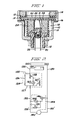
- the sensor of Figure 1 is essentially a copper-air battery. It includes an outer casing 10, which is preferably a polymeric material, having an insulating bushing 12 at its lower end and an externally threaded plastic insert 14 at its upper end. Between the bushing 12 and the insert 14 are essential elements of the sensor. An impervious washer 13 is positioned between the upper portion of bladder 15 and insert 14. This holds the top inwardly extending portion of bladder 15 against the outer portions of membrane 20 and defines the area of membrane 20 exposed to the atmosphere. An expansion bladder 15, of neoprene or other suitable rubber such as ethylene propylene rubber, laterally surrounds the essential components of the battery and is positioned between these elements and the casing 10.
- an outer casing 10 which is preferably a polymeric material, having an insulating bushing 12 at its lower end and an externally threaded plastic insert 14 at its upper end. Between the bushing 12 and the insert 14 are essential elements of the sensor.
- An impervious washer 13 is positioned between the upper portion of bladder 15 and insert 14.
- the bladder 15 is spaced from the walls of the casing in the lower portion of the casing to permit its lateral expansion and vent holes 16 provide means by which gas pressure is equilibrated in the space 18, between the casing and the bladder, and the outside atmosphere.
- a polymer membrane 20 At the upper part of the essential elements of the sensor is a polymer membrane 20.
- the polymer membrane has the capacity to perfuse and pass oxygen at a rate which is proportional to the partial pressure of oxygen in contact with the exterior surface of the membrane. Oxygen which is in contact with the exterior of the sensor passes through the membrane 20 and into contact with a sensing electrode 22.
- the sensing electrode is porous metal and it is gold plated.
- the function of the gold on the sensing electrode is that of catalyzing the electro-reduction of oxygen.
- the extent of gold plating must be sufficient to permit effective reduction of the oxygen and the degree of plating to achieve such effective reduction will be apparent to those skilled in the art.
- the porous sensing electrode makes contact with and has its pores wetted with potassium hydroxide electrolyte contained within the internal chamber of the sensor where a porous copper counter electrode 24 is located.
- the copper counter electrode is separated from the sensing electrode 22 by the insulating ring 28 which may itself be porous.
- Suitable circuitry such as is illustrated in and described with reference to Figure 2 is provided between the sensing electrode 122 and the copper counter electrode 124.
- the elements of Figure 2 corresponding to those of Figure 1 have an assigned reference numeral which is 100 higher than the reference numerals of Figure 1.
- This circuitry includes connecting wires 130 and 132 and a resistance network 144 which includes thermistor 148 to compensate for temperature variations.
- the network 144 enclosed by dashed lines in Figure 2, is provided in parallel with a voltage meter 140 to permit a selected voltage to be developed between lines 130 and 132.
- the network consists of a variable resistor 146 in series with a thermistor 148, and a second variable resistor 150 in parallel with thermistor 148.
- the circuitry also includes a voltmeter from which readings can be taken of the voltage drop across the resistance network 144 resulting from the current flow between the sensing electrode 122 and the porous copper counter electrode 124 to provide an indication of the partial pressure of oxygen which is in contact with the exterior surface of the polymer membrane 20 of Figure 1.
- the oxygen-diffusing membrane is a composite of fluorinated ethylene propylene polymer (FEP) and tetrafluoro ethylenepolymer (PTFE).
- FEP fluorinated ethylene propylene polymer
- PTFE tetrafluoro ethylenepolymer
- the membrane may be formed of other polymers suitably permeable to oxygen such as polysulfone. See in this connection U.S. Patent 3,616,411 as to other alternative membranes.
- the potassium hydroxide solution is a 25 weight % KOH electrolyte.
- the thickness of the oxygen permeable membrane is typically about 0.025 mm.
- the sensing electrode is a disk with a 3.3 cm diameter and a 0.14 cm thickness.
- the counter electrode is a copper cylinder weighing 7.6 gm. with a center bore. It has an outer diameter of 1.8 cm, an inner diameter of 0.8 cm and a length of 1.2 cm.
- the spacing between the sensing electrode and the counter electrode is of the order of one millimeter and is not critical.
- the resistor network 144 described below has a resistance of 110 ohms. Exposure of the sensor to air at 1 atmosphere pressure produces a current of about 400 microamperes (pa) and an output voltage of 44 millivolts across the resistor network. This voltage is read with a voltmeter connected across the resistor network and with a dial calibrated to read in terms of partial pressures of oxygen. If the exposed surface of the membrane 20 of Figure 1 and the resistance values of the resistor network 144 of Figure 2 and the concentration of oxygen in air at constant temperature to which the sensor is exposed are all maintained as provided in prior art devices as specified above, the life of the prior art sensor is about 8800 hours.
- a coulometer subcircuit 154 which may be connected in series in line 132 between counter electrode 124 and resistor network 144 provides a monitoring of the history of past use of the sensor and the portion of the overall life already consumed and, reciprocally, an indication of the remaining life or life expectancy of the sensor.
- This subcircuit comprises a thermally compensated resistor network connected in parallel with a coulometer.
- the coulometer subcircuit 154 may alternatively be connected in series in line 130 between sensing electrode 122 and the resistor network 144.
- Coulometer 156 is a conventional coulometer which is connected in parallel with a thermally compensated resistor network having a preferred overall resistance value of the order of one tenth to one hundredth of the resistance of the coulometer itself. This arrangement permits a known fraction of the total current to pass through the coulometer.
- the resistor network of subcircuit 154 is similar to resistor network 144 and includes two variable resistors 158 and 160 connected in series in line 132.
- a thermistor 162 is connected in parallel with variable resistor 160 as part of the network.
- Coulometer 156 and the remaining elements of the network are adjusted to provide a visible indication of the degree to which the counterelectrode 124 has been oxidized and also conversely to provide a visible indication of the extent or proportion of the counterelectrode which remains unoxidized.
- Coulometers are preferred for use in the circuitry of the present invention. Coulometers based on transposing mercury, silver, copper, etc. across a small gap containing an aqueous ionic solution to a counter electrode, all in a capillary tube serve usefully in the combination and in the circuitry as illustrated in Figure 2. The expended life is indicated by movement of the gap along the length of the capillary as metal is transferred from one side to the other.
- the purpose of the thermally compensated resistor network of subcircuit 154 is to allow for the temperature coefficient of resistance of the coulometer and to ensure that the rate and extent of change of the linear display of coulometer remains proportional to the total current at all times, and corresponds to the rate and extent of oxidation of counterelectrode 124.
- the rate of oxidation of counterelectrode 124 and, accordingly, the overall life of an oxygen sensor cell as described with reference to Figure 1 depends on the size of the area of the sensing electrode 122 which is exposed to the ambient atmosphere as is explained more fully in copending application Serial No. 641,650, filed August 17, 1984. Hence the values of the resistance and thermistor in coulometer network 154 will vary with the size of the sensing electrode.
- FIG. 1 contains the details of the casing 10 for the oxygen sensor.
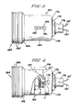
- the sensor as illustrated in Figure 1, is preferably housed within an outer housing as illustrated in Figures 3 and 4.
- the housing 160 includes an inner cylindrical main body portion 162.
- the housing 160 is generally cylindrical and is adapted to contain the generally cylindrical structure of Figure 1.
- the casing 10 of the structure of Figure 1 is introduced into the enlarged cylindrical end 164 of the housing 160.
- a tapered portion 166 of housing 160 connects the inner cylindrical portion 162 and the outer enlarged cylindrical end 164.
- means, such as a number of recesses 168, may be formed to facilitate the mounting of the structure into a panel or into other supporting structure where the partial pressure of the oxygen in the atmosphere is to be sensed.
- an attachment bolt 170 may be employed to hold a circuit housing 11 within the housing 160.
- a washer or spacer 172 is disposed between the nut 170 and the end 174 of housing 160.
- Other auxiliary structure 176 which may be, for example, means for holding conductors such as 130' and 132', may extend to an oxygen partial pressure display such as 140 of Figure 2 (but not shown in Figures 3 and 4). Such display is mounted in the space craft instrument panel for easy observation.
- a calibrated display coulometer 156 may also be provided and attached as illustrated in the Figure 3 to the housing 160.
- a site glass 182 of coulometer 156 is mounted externally of the housing 160 to permit visual inspection of the site glass 182 relative to a scale 184.
- Site glass 182 is a portion of the coulometer designated as 156 in Figure 2.
- the coulometer used may be a conventional silver coulometer or a mercury coulometer of conventional construction having an indicating means such as a site glass.
- FIG 4 two lead wires 155 and 157 extending from coulometer 156 and corresponding to similar wires in Figure 2, are shown partially in phantom in Figure 4.
- the wires 155 and 157 provide electrical connection between the coulometer 156 and the circuitry which is contained within the circuit housing 11 of the oxygen sensor within housing 160.
- the oxygen sensor 10 of Figure 4 is also illustrated to be electrically connected by wires 130 and 132 to circuit housing 11.
- the wires 130' and 132' extend from auxiliary structure 176 and can connect the sensor within housing 160 to a voltmeter such as 140 of Figure 2.
- the housing 160 may be removed from its mounting in a panel or other structure within a space craft so that the coulometer 156 can be viewed. This is all that is needed in order to make a determination as to the extent to which the entire life of the device has been consumed and the extent to which a portion of the life remains.
- Adjustment of the variable resistors within the circuit housing 11 may be accomplished by turning four adjustment screws, the head 178 of one of which is shown to extend through the housing 160 so as to be available for turning adjustment from the exterior of the housing 160.
Landscapes
- Chemical & Material Sciences (AREA)
- Health & Medical Sciences (AREA)
- Life Sciences & Earth Sciences (AREA)
- General Physics & Mathematics (AREA)
- Engineering & Computer Science (AREA)
- Pathology (AREA)
- Immunology (AREA)
- Physics & Mathematics (AREA)
- Analytical Chemistry (AREA)
- Biochemistry (AREA)
- General Health & Medical Sciences (AREA)
- Food Science & Technology (AREA)
- Medicinal Chemistry (AREA)
- Combustion & Propulsion (AREA)
- Molecular Biology (AREA)
- Chemical Kinetics & Catalysis (AREA)
- Electrochemistry (AREA)
- Measuring Oxygen Concentration In Cells (AREA)
- Investigating Or Analyzing Materials By The Use Of Fluid Adsorption Or Reactions (AREA)
- Investigating Or Analyzing Non-Biological Materials By The Use Of Chemical Means (AREA)
Applications Claiming Priority (2)
| Application Number | Priority Date | Filing Date | Title |
|---|---|---|---|
| US66793584A | 1984-11-02 | 1984-11-02 | |
| US667935 | 1984-11-02 |
Publications (2)
| Publication Number | Publication Date |
|---|---|
| EP0180138A2 true EP0180138A2 (fr) | 1986-05-07 |
| EP0180138A3 EP0180138A3 (fr) | 1989-07-05 |
Family
ID=24680280
Family Applications (1)
| Application Number | Title | Priority Date | Filing Date |
|---|---|---|---|
| EP85113449A Withdrawn EP0180138A3 (fr) | 1984-11-02 | 1985-10-23 | Capteur d'oxygène avec indicateur de vie résiduelle |
Country Status (2)
| Country | Link |
|---|---|
| EP (1) | EP0180138A3 (fr) |
| JP (1) | JPS61112956A (fr) |
Cited By (7)
| Publication number | Priority date | Publication date | Assignee | Title |
|---|---|---|---|---|
| EP0459782A3 (en) * | 1990-05-31 | 1993-10-20 | Capital Controls Co Inc | Amperimetric measurement with cell electrode deplating |
| GB2340612A (en) * | 1998-08-18 | 2000-02-23 | Ind Scient Corp | Determining end of useful life of electrochemical gas sensor with consumable electrode |
| WO2005050193A1 (fr) * | 2003-11-12 | 2005-06-02 | Teledyne Technologies Incorporated | Detecteur de gaz a dispositif de commande, et systeme et procede pour l'utiliser |
| FR2865277A1 (fr) * | 2004-01-16 | 2005-07-22 | Draeger Safety Ag & Co Kgaa | Appareil de mesure de gaz equipe d'un detecteur electrochimique |
| US6975967B2 (en) * | 2001-07-31 | 2005-12-13 | Revco Technologies, Inc. | CO2/O2 incubator predictive failure for CO2 and O2 sensors |
| US7664607B2 (en) | 2005-10-04 | 2010-02-16 | Teledyne Technologies Incorporated | Pre-calibrated gas sensor |
| CN102116760A (zh) * | 2009-12-31 | 2011-07-06 | 北京谊安医疗系统股份有限公司 | 用于检测氧浓度传感器消耗程度的装置与方法 |
Families Citing this family (2)
| Publication number | Priority date | Publication date | Assignee | Title |
|---|---|---|---|---|
| JP5077828B2 (ja) * | 2008-04-15 | 2012-11-21 | 横河電機株式会社 | 電気化学センサ |
| JP6559443B2 (ja) * | 2015-03-10 | 2019-08-14 | 三男 ▲高▼橋 | 酸素センサ及び計測装置 |
Family Cites Families (3)
| Publication number | Priority date | Publication date | Assignee | Title |
|---|---|---|---|---|
| DE1929135A1 (de) * | 1968-06-11 | 1969-12-18 | Gen Electric | Elektrolytische Sauerstoffmesszelle |
| US3948746A (en) * | 1975-01-20 | 1976-04-06 | Fischer & Porter Co. | Dissolved oxygen probe |
| GB1571282A (en) * | 1976-03-11 | 1980-07-09 | City Tech | Gas sensor |
-
1985
- 1985-10-23 EP EP85113449A patent/EP0180138A3/fr not_active Withdrawn
- 1985-11-01 JP JP60244272A patent/JPS61112956A/ja active Pending
Cited By (9)
| Publication number | Priority date | Publication date | Assignee | Title |
|---|---|---|---|---|
| EP0459782A3 (en) * | 1990-05-31 | 1993-10-20 | Capital Controls Co Inc | Amperimetric measurement with cell electrode deplating |
| GB2340612A (en) * | 1998-08-18 | 2000-02-23 | Ind Scient Corp | Determining end of useful life of electrochemical gas sensor with consumable electrode |
| GB2340612B (en) * | 1998-08-18 | 2003-02-26 | Ind Scient Corp | Method for determining exhaustion of an electrochemical gas sensor |
| US6975967B2 (en) * | 2001-07-31 | 2005-12-13 | Revco Technologies, Inc. | CO2/O2 incubator predictive failure for CO2 and O2 sensors |
| WO2005050193A1 (fr) * | 2003-11-12 | 2005-06-02 | Teledyne Technologies Incorporated | Detecteur de gaz a dispositif de commande, et systeme et procede pour l'utiliser |
| FR2865277A1 (fr) * | 2004-01-16 | 2005-07-22 | Draeger Safety Ag & Co Kgaa | Appareil de mesure de gaz equipe d'un detecteur electrochimique |
| US7664607B2 (en) | 2005-10-04 | 2010-02-16 | Teledyne Technologies Incorporated | Pre-calibrated gas sensor |
| CN102116760A (zh) * | 2009-12-31 | 2011-07-06 | 北京谊安医疗系统股份有限公司 | 用于检测氧浓度传感器消耗程度的装置与方法 |
| CN102116760B (zh) * | 2009-12-31 | 2013-10-23 | 北京谊安医疗系统股份有限公司 | 用于检测氧浓度传感器消耗程度的装置与方法 |
Also Published As
| Publication number | Publication date |
|---|---|
| JPS61112956A (ja) | 1986-05-30 |
| EP0180138A3 (fr) | 1989-07-05 |
Similar Documents
| Publication | Publication Date | Title |
|---|---|---|
| US8002957B2 (en) | Sensor apparatus for measuring and detecting acetylene and hydrogen dissolved in a fluid | |
| US5667653A (en) | Electrochemical sensor | |
| US3718568A (en) | Electrochemical sensor instrumentation | |
| US4686011A (en) | Method for the protection of and/or monitoring of changes in a reference system in analytical measuring engineering, and reference system with a reference electrode | |
| US4473458A (en) | Ion measuring device with self-contained storage of standardizing solution | |
| US20030132755A1 (en) | pH sensor with internal solution ground | |
| GB2094005A (en) | Electrochemical gas sensor | |
| US6602401B1 (en) | Amperometric sensor for low level dissolved oxygen with self-depleting sensor design | |
| US4377460A (en) | Solid electrolyte gas sensing apparatus | |
| EP0180138A2 (fr) | Capteur d'oxygène avec indicateur de vie résiduelle | |
| KR20060055543A (ko) | 수소 가스센서 | |
| US5363690A (en) | Gas detection apparatus | |
| US3826730A (en) | Disposable electrochemical electrode | |
| US4948496A (en) | Gas sensor | |
| CA1192259A (fr) | Cellule detectrice d'oxygene | |
| US5902467A (en) | Oxygen sensor based on a metal-air battery | |
| EP2002251B1 (fr) | Capteur d'oxygène | |
| US3718562A (en) | Electrode assembly | |
| US4652359A (en) | Portable oxygen sensor with shortened break-in time | |
| Lucero | Design of membrane-covered polarographic gas detectors | |
| WO1981002831A1 (fr) | Dispositif et procede de mesure de la pression partielle de l'oxygene et d'un gaz qui en solution aqueuse produit une base ou un acide | |
| EP0171740A2 (fr) | Capteur d'oxygène à grande durée de vie | |
| US20050098447A1 (en) | Gas sensor with controller, and system and method for employing same | |
| Neville | Electrochemical device for measuring oxygen | |
| US4498970A (en) | Electrochemical gas sensor |
Legal Events
| Date | Code | Title | Description |
|---|---|---|---|
| PUAI | Public reference made under article 153(3) epc to a published international application that has entered the european phase |
Free format text: ORIGINAL CODE: 0009012 |
|
| AK | Designated contracting states |
Kind code of ref document: A2 Designated state(s): DE FR GB IT |
|
| PUAL | Search report despatched |
Free format text: ORIGINAL CODE: 0009013 |
|
| AK | Designated contracting states |
Kind code of ref document: A3 Designated state(s): DE FR GB IT |
|
| 17P | Request for examination filed |
Effective date: 19891207 |
|
| 17Q | First examination report despatched |
Effective date: 19910215 |
|
| STAA | Information on the status of an ep patent application or granted ep patent |
Free format text: STATUS: THE APPLICATION IS DEEMED TO BE WITHDRAWN |
|
| 18D | Application deemed to be withdrawn |
Effective date: 19910625 |
|
| RIN1 | Information on inventor provided before grant (corrected) |
Inventor name: NIEDRACH, LEONARD WILLIAM Inventor name: WILL, FRITZ GUSTAV |