EP0180140A2 - Verfahren und Vorrichtung zum Nachweis von Verunreinigungen in einer Flüssigkeit - Google Patents
Verfahren und Vorrichtung zum Nachweis von Verunreinigungen in einer Flüssigkeit Download PDFInfo
- Publication number
- EP0180140A2 EP0180140A2 EP85113454A EP85113454A EP0180140A2 EP 0180140 A2 EP0180140 A2 EP 0180140A2 EP 85113454 A EP85113454 A EP 85113454A EP 85113454 A EP85113454 A EP 85113454A EP 0180140 A2 EP0180140 A2 EP 0180140A2
- Authority
- EP
- European Patent Office
- Prior art keywords
- impurities
- analyzing
- phase
- light
- liquid
- Prior art date
- Legal status (The legal status is an assumption and is not a legal conclusion. Google has not performed a legal analysis and makes no representation as to the accuracy of the status listed.)
- Granted
Links
- 239000012535 impurity Substances 0.000 title claims abstract description 149
- 239000007788 liquid Substances 0.000 title claims abstract description 82
- 238000000034 method Methods 0.000 title claims abstract description 29
- 238000001514 detection method Methods 0.000 claims abstract description 41
- 230000001678 irradiating effect Effects 0.000 claims abstract description 4
- 239000002245 particle Substances 0.000 claims description 68
- 229910021642 ultra pure water Inorganic materials 0.000 claims description 28
- 239000012498 ultrapure water Substances 0.000 claims description 28
- 238000004519 manufacturing process Methods 0.000 claims description 8
- 239000010842 industrial wastewater Substances 0.000 claims description 4
- 238000007872 degassing Methods 0.000 claims description 3
- 230000035945 sensitivity Effects 0.000 claims description 3
- 230000010355 oscillation Effects 0.000 claims description 2
- CURLTUGMZLYLDI-UHFFFAOYSA-N Carbon dioxide Chemical compound O=C=O CURLTUGMZLYLDI-UHFFFAOYSA-N 0.000 claims 2
- 229910002092 carbon dioxide Inorganic materials 0.000 claims 1
- 239000001569 carbon dioxide Substances 0.000 claims 1
- 239000000126 substance Substances 0.000 abstract description 9
- 230000001131 transforming effect Effects 0.000 abstract description 3
- XLYOFNOQVPJJNP-UHFFFAOYSA-N water Substances O XLYOFNOQVPJJNP-UHFFFAOYSA-N 0.000 description 14
- 238000005259 measurement Methods 0.000 description 10
- 238000010586 diagram Methods 0.000 description 7
- 238000004458 analytical method Methods 0.000 description 5
- 239000012528 membrane Substances 0.000 description 5
- VYPSYNLAJGMNEJ-UHFFFAOYSA-N Silicium dioxide Chemical compound O=[Si]=O VYPSYNLAJGMNEJ-UHFFFAOYSA-N 0.000 description 4
- 238000004867 photoacoustic spectroscopy Methods 0.000 description 4
- 230000008569 process Effects 0.000 description 4
- 239000003792 electrolyte Substances 0.000 description 3
- 239000010419 fine particle Substances 0.000 description 3
- 238000000746 purification Methods 0.000 description 3
- 239000000725 suspension Substances 0.000 description 3
- 238000000108 ultra-filtration Methods 0.000 description 3
- 241000894006 Bacteria Species 0.000 description 2
- OKTJSMMVPCPJKN-UHFFFAOYSA-N Carbon Chemical compound [C] OKTJSMMVPCPJKN-UHFFFAOYSA-N 0.000 description 2
- TZCXTZWJZNENPQ-UHFFFAOYSA-L barium sulfate Chemical compound [Ba+2].[O-]S([O-])(=O)=O TZCXTZWJZNENPQ-UHFFFAOYSA-L 0.000 description 2
- 229910052793 cadmium Inorganic materials 0.000 description 2
- BDOSMKKIYDKNTQ-UHFFFAOYSA-N cadmium atom Chemical compound [Cd] BDOSMKKIYDKNTQ-UHFFFAOYSA-N 0.000 description 2
- 230000004907 flux Effects 0.000 description 2
- 238000005342 ion exchange Methods 0.000 description 2
- 150000002500 ions Chemical class 0.000 description 2
- 230000031700 light absorption Effects 0.000 description 2
- 239000000463 material Substances 0.000 description 2
- 230000003204 osmotic effect Effects 0.000 description 2
- QEVHRUUCFGRFIF-MDEJGZGSSA-N reserpine Chemical compound O([C@H]1[C@@H]([C@H]([C@H]2C[C@@H]3C4=C(C5=CC=C(OC)C=C5N4)CCN3C[C@H]2C1)C(=O)OC)OC)C(=O)C1=CC(OC)=C(OC)C(OC)=C1 QEVHRUUCFGRFIF-MDEJGZGSSA-N 0.000 description 2
- 238000005070 sampling Methods 0.000 description 2
- 239000004065 semiconductor Substances 0.000 description 2
- 235000012239 silicon dioxide Nutrition 0.000 description 2
- 239000000377 silicon dioxide Substances 0.000 description 2
- UOFGSWVZMUXXIY-UHFFFAOYSA-N 1,5-Diphenyl-3-thiocarbazone Chemical compound C=1C=CC=CC=1N=NC(=S)NNC1=CC=CC=C1 UOFGSWVZMUXXIY-UHFFFAOYSA-N 0.000 description 1
- 238000010521 absorption reaction Methods 0.000 description 1
- 238000004847 absorption spectroscopy Methods 0.000 description 1
- 238000004364 calculation method Methods 0.000 description 1
- 238000011088 calibration curve Methods 0.000 description 1
- 238000004587 chromatography analysis Methods 0.000 description 1
- 238000004737 colorimetric analysis Methods 0.000 description 1
- 238000010276 construction Methods 0.000 description 1
- 238000009792 diffusion process Methods 0.000 description 1
- 238000004821 distillation Methods 0.000 description 1
- 230000000694 effects Effects 0.000 description 1
- 238000010353 genetic engineering Methods 0.000 description 1
- 238000009434 installation Methods 0.000 description 1
- 230000010354 integration Effects 0.000 description 1
- 238000010327 methods by industry Methods 0.000 description 1
- 238000003908 quality control method Methods 0.000 description 1
- 150000003839 salts Chemical class 0.000 description 1
- 230000001954 sterilising effect Effects 0.000 description 1
- 238000004613 tight binding model Methods 0.000 description 1
- 230000009466 transformation Effects 0.000 description 1
- 230000007704 transition Effects 0.000 description 1
- 238000011144 upstream manufacturing Methods 0.000 description 1
- 239000002351 wastewater Substances 0.000 description 1
- 238000004065 wastewater treatment Methods 0.000 description 1
Images


Classifications
-
- G—PHYSICS
- G01—MEASURING; TESTING
- G01N—INVESTIGATING OR ANALYSING MATERIALS BY DETERMINING THEIR CHEMICAL OR PHYSICAL PROPERTIES
- G01N21/00—Investigating or analysing materials by the use of optical means, i.e. using sub-millimetre waves, infrared, visible or ultraviolet light
- G01N21/17—Systems in which incident light is modified in accordance with the properties of the material investigated
- G01N21/1702—Systems in which incident light is modified in accordance with the properties of the material investigated with opto-acoustic detection, e.g. for gases or analysing solids
Definitions
- This invention relates to a method and an apparatus for analyzing impurities in liquid, and more particularly to a method and an apparatus for analyzing impurities in various kinds of liquid such as ultra-pure water adapted to classify the impurities into soluble substance, insoluble substance and impurities in the form of bubbles, and to measure their concentrations separately.
- the photoacoustic analyzing method can be applied to highly sensitive analyzing and is useful not only for analysis of true solutions but also for that of suspensions.
- no technique has been known, which is adapted to measure separately not only insoluble impurities but also soluble ones (impurities in the form of ions) in liquid, utilizing such characteristics as described above of the photoacoustic analyzing method. This is because theoretical relations between measurement conditions such as the light modulation frequency for the photoacoustic analyzing apparatus and information obtained under those conditions are not known.
- the amount of impurities contained in ultra-pure water is in the order of ppt's and this concentration level is below the lower detection limit of the conventional analyzing method such as chromatography, colorimetry, etc. Consequently, it is difficult to apply the prior art analyzing methods to analysis of impurities in ultra-pure water.
- the object of this invention is to provide a method for analyzing impurities in liquid and an apparatus therefor, which are adapted to classify impurities in liquid to be measured into soluble and insoluble impurities as well as those in the form of bubbles, and to measure their concentration separately.
- a method for analyzing impurities in liquid is carried out by measuring a photoacoustic signal obtained by irradiating onto a liquid to be measured an intensity-modulated light, obtaining the relationship between the modulation frequency of the intensity-modulated light (light modulation frequency) and the phase of the photoacoustic signal, and determining the kinds of impurities in the liquid, as classified into soluble and insoluble ones and those in the form of bubbles on the basis of the information thus obtained.
- an apparatus for analyzing impurities in liquid comprising a light source; at least one light modulator for transforming light from the light source into intensity-modulated light having a given constant frequency; at least one cell disposed at a position where it is irradiated with the intensity-modulated light and containing therein liquid to be measured; at least one phase detection device for detecting the phase of the photoacoustic signals coming from the cell; a calculating device for analyzing impurities in the liquid on the basis of information obtained by the phase detection device; and a control device for controlling the modulation frequency (light modulation frequency) of the intensity-modulated light derived from the light modulator.
- a photoacoustic signal obtained by irradiating onto a liquid sample such as ultra-pure water an intensity-modulated light is measured and the kinds of impurities in the liquid sample as classified into soluble and insoluble substances and substance in the form of bubbles and the concentrations thereof are determined on the basis of the relation between the modulation frequency (light modulation frequency) of the intensity-modulated light and the phase, as well as the intensity, of the photoacoustic signal.
- the principle of this invention is based on the fact that the relation between the light modulation frequency and the phase of the photoacoustic signals varies depending on the property of impurities, as indicated in Table 1.
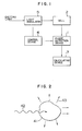
- an impurity particle 41 absorbs light 42 and releases heat produced by a radiationless transition in the form of a thermal flux 43 in the medium.
- This thermal flux by J J is given by the following equation, which is produced according to a temperature field T(p, t) formed around the impurity particle;
- Eqs. (14) and (15) may be represented in a polar coordinate system, as follows;
- ⁇ Q represents the phase delay due to propagation of the photoacoustic signals and ⁇ D indicates the phase delay of the photoacoustic signal due to the time interval required for release of heat produced in the impurity particles.
- the photoacoustic signal is an acoustic wave having linear characteristics, the principle of superposition is applied to the signal. Under these conditions, the intensity of the photoacoustic signal corresponds to the sum of the concentration of soluble impurities and that of insoluble ones and the resultant phase is ⁇ Q . Therefore, when the phase 8 of the lock-in amplifier for the photoacoustic signal is set at the intensity of the phase-detected photoacoustic signal represents the total amount of impurities contained in the solution. On the other hand, when ⁇ 0 satisfies and ⁇ D is distinguishable from ⁇ Q , it can be understood that the insoluble impurities can be measured separately from soluble ones.
- the projected light is refracted by bubbles, changes its path and can enter directly the detector.
- the incident light produces photoacoustic signals of the detector itself.
- the phase of the photoacoustic signal is zero. Consequently, it is possible to measure bubbles, distinguishing them from soluble and insoluble impurities.
- Fig. 1 is a block diagram showing the basic structure of this invention.
- Light emitted by a light source enters a light modulator 5, in which the incident light is transformed into intensity-modulated light, whose intensity varies with a constant frequency, and a cell 2 containing a liquid sample to be measured is irradiated with this intensity-modulated light.
- the reference numeral 1 represents a phase detection device having functions to receive photoacoustic signals obtained at the cell 2 and measure the phase and the intensity of the photoacoustic signal or to take out only the photoacoustic signal which has a given phase from the received signal and measure its intensity.
- the reference numeral 4 indicates a control device, which sets the light modulation frequency in the light modulator 5 and also the phase in the phase detection device 1.
- the reference numeral 7 represents a calculating device, which classifies impurities contained in the liquid sample, calculates their amount (concentration), and displays results, if necessary, on the basis of information obtained by the phase detection device 1.
- Fig. 3 shows the first embodiment of an apparatus for analyzing impurities in liquid, in which the light modulation frequency can be set at any desired value and a lock-in amplifier is used as the phase detection device 1 for detecting the phase of the photoacoustic signals, the phase and the sensitivity of the lock-in amplifier 1 also being settable at any desired values.
- the light modulation frequency as well as the phase and the sensitivity of the lock-in amplifier are controlled by the control device coupled with a calculator on the basis of Table 1.
- a sample such as ultra-pure water, etc. is prepared and filled in a sealed type cell 2 and the photoacoustic signal derived from the sample is measured.
- an Ar laser device is used as the light source 3 and a light beam of 2.6 W having an oscillation line of 488 nm is utilized as exciting light.
- the light modulation frequency is set at 80 Hz for low frequency modulation and at 410 kHz for high frequency modulation. These light modulation frequencies sufficiently satisfy Eqs. (23) and (24), respectively, for particles of silicon dioxide having a radius of 1 ⁇ m in water.
- the phase of the lock-in amplifier 1 is set automatically at a value as mentioned before by the controller (control device) 4 and measures only the intensity of the photoacoustic signal. In this way, the total amount of impurities (concentration) in the sample can be obtained.
- the lower detection limit of the light-absorption coefficient is about 10 -8 /cm.
- the impurities are silicon dioxide particles, they can be measured down to about 20 ppt.
- the light modulation frequency is set automatically at the high frequency side and the lock-in amplifier acts as a phase detector. In this case, for a particle radius of 1 ⁇ m the phase is 45 degrees and the smallest measurable value of the phase detector of 0.5 degree corresponds to a particle radius of about 0.1 ⁇ m.
- the reference numeral 5 is the photoacoustic modulator transforming light coming from the Ar laser 3 into modulated light; 6 is the oscillator feeding the lock-in amplifier 1 and the photoacoustic modulator 5 with signals; and 7 represents the calculator (calculating device). Further, since a photoacoustic modulator 5 is used as the light modulator 5, an oscillator 6 is disposed, which drives the modulator.
- Fig. 4 the second embodiment of the apparatus according to this invention will be explained, referring to Fig. 4.
- flow type cells are used and 2 sets of light modulators M 1 , M 2' cells 2a, 2b combining the same sample and lock-in amplifiers la, lb are disposed. These 2 sets are adjusted for different measurement conditions.
- the light source 3 is an Ar laser device having an output 20 W.
- the light modulator M 1 is set at 80 Hz and M 2 at 410 kHz.
- the setting value of these light modulation frequencies can be varied by the control device 4.
- the lock-in amplifier la measures the intensity S 1 and lb measures variations in phase ⁇ D and the intensity S 2 .
- the measured values S 1 , S 2 and ⁇ D are processed by a calculator 7.
- the reference numeral 8 indicates a light distributing device disposed between the light source 3 and the light modulators M 1 , M 2' that is, 8a is a beam splitter, which directs the incident light beam toward 2 directions, and 8b is a mirror, which reflects the incident beam.
- the liquid sample 35 flows successively through the-cells 2a and 2b by means of a pump 36.
- Fig. 5 shows an example of measurements according to this embodiment. The figure shows that soluble impurities of 20 ppb flows in the region A and impurities of 60 ppt having a particle radius of 0.3 ⁇ m are detected in the region B. In the region C impurities of 30 ppt in the form of particles having a particle radius of 0.15 ⁇ m are detected. In the region D no impurities are detected.
- the relationship between the intensity of signals and the concentration in this apparatus is as follows;
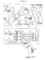
- Fig. 6 shows the third embodiment of this invention, in which the method according to this invention is applied to an ultra-pure water production apparatus.
- the reference numeral 10 indicates a raw water supply line for feeding a distillation tower 11 with raw water such as city water; 12 is an activated charcoal filter tower for eliminating organic impurities; 13 is an inverse osmotic membrane module for eliminating particles, electrolyte, etc.; 14 is an intermediate tank; 15 is an ion exchange resine tower for eliminating electrolyte, etc.; 16 is a pure water tank for storing produced pure water (specific resistance greater than 1 - 10 M ⁇ cm); 17 is an ultra-violet ray sterilizer for sterilizing bacteria; 18 is a polisher for eliminating electrolyte; and 19 is an ultra-filtration membrane module for eliminating fine particles.
- This ultra-filtration membrane module 19 feeds a 5-way valve 20 with ultra-pure water, whose specific resistance is greater than 17-18 M ⁇ cm and in which the number of fine particles larger than 0.1-0.2 ⁇ m is smaller than 50/cc and that of living bacteria is smaller than 0.1/cc.
- 21 to 24 represent water sending pumps or pressuring pumps.
- Produced ultra-pure water is supplied successively from the 5-way valve 20 to the cells 2a, 2b and 2c of the apparatus 25 for analyzing impurities.
- 3a indicates a light source utilizing a high energy C0 2 laser; 9a is a beam splitter; 9c is a half mirror; 9b is a mirror; M 1 , M 2 and M 3 are light modulators; la, lb and lc are lock-in amplifiers; 4 is a controlling device controlling the light modulators M 1 to M 3 and the lock-in amplifiers la to lc; and 7 is a calculating device for classifying impurities into various sorts and calculating their concentration on the basis of information coming from the lock-in amplifiers la to lb.
- This calculating device 7 is provided also with the function to control a valve 10a mounted on the raw water supply line 10, the 5-way valve 20 and another valve 27, depending on analysis results of the produced ultra-pure water.
- the light modulation frequency w l of the light modulator M 1 is set at 33 Hz and the light frequencies w 2 and w 3 of the light modulators M 2 and M 3 , respectively, are set at 4 MHz.
- the total amount of impurities and the amount of soluble impurities are measured on the basis of the intensity of the photoacoustic signals S 1 and S 2 , respectively.
- the lock-in amplifier lc measures the phase ⁇ and the intensity S 3 of the photoacoustic signals.
- the mean radius of particles of insoluble impurities is obtained from the phase ⁇ and the concentration of the insoluble impurities is calculated on the basis of the intensity S 3 .
- the signals coming from the lock-in amplifiers la-lc are directly inputted to the calculating device 26 and control the 5-way valve 20 described above as follows.
- the analyzing apparatus 25 can be also so constructed that only a part of the produced ultra-pure water is bypassed therethrough.
- Fig. 7 shows the fourth embodiment of this invention, in which an apparatus for analyzing impurities according to this invention is applied to industrial waste water.
- the reference numerals, which are used also in Fig. 4 or Fig. 6, represent identical or corresponding parts.
- the reference numeral 29 indicates a waste water ejecting line; 30 is a waste water treatment installation; 31 is a storing reservoir; and 32 is a sampling device. Samples taken in this sampling device 32 are supplied successively to the cells 2a, 2b and 2c of the apparatus for analyzing impurities.
- an Ar laser device of 5 W is used as the light source 3.
- the other conditions are identical to those described for the embodiment illustrated in Fig. 6.
- the photoacoustic signals (PA signals) coming from the cells 2a to 2c are inputted to the lock-in amplifiers la to lc, respectively, and the intensities S l to S 3 of the photoacoustic signals from the lock-in amplifiers la to lc as well as the phase O D of the photoacoustic signals from the lock-in amplifier lc are inputted to the display-recording device (calculating device) 7.
- the samples, which have passed through the cells 2a to 2c, are ejected by the drain.
- Fig. 8 shows a result obtained by analyzing industrial waste water by means of the apparatus indicated in Fig. 7.
- the apparatus for analyzing impurities according to this invention can be applied to the case where samples to be analyzed are turbid and suspended.
- impurities in liquid are analyzed on the basis of information on the modulation frequency of intensity-modulated light, with which liquid samples are irradiated, the relationship between the phase of the intensity-modulated light and that of the photoacoustic signal, and the intensity of the photoacoustic signal, it is possible to classify impurities in liquid into soluble and insoluble ones and those in the form of bubbles and also to measure their concentration separately.
Landscapes
- Physics & Mathematics (AREA)
- Health & Medical Sciences (AREA)
- Life Sciences & Earth Sciences (AREA)
- Chemical & Material Sciences (AREA)
- Analytical Chemistry (AREA)
- Biochemistry (AREA)
- General Health & Medical Sciences (AREA)
- General Physics & Mathematics (AREA)
- Immunology (AREA)
- Pathology (AREA)
- Investigating Or Analysing Materials By Optical Means (AREA)
- Investigating Or Analyzing Materials By The Use Of Ultrasonic Waves (AREA)
Applications Claiming Priority (2)
| Application Number | Priority Date | Filing Date | Title |
|---|---|---|---|
| JP59224947A JPS61102541A (ja) | 1984-10-25 | 1984-10-25 | 液体中の不純物分析方法および装置 |
| JP224947/84 | 1984-10-25 |
Publications (3)
| Publication Number | Publication Date |
|---|---|
| EP0180140A2 true EP0180140A2 (de) | 1986-05-07 |
| EP0180140A3 EP0180140A3 (en) | 1988-10-12 |
| EP0180140B1 EP0180140B1 (de) | 1992-05-20 |
Family
ID=16821684
Family Applications (1)
| Application Number | Title | Priority Date | Filing Date |
|---|---|---|---|
| EP85113454A Expired - Lifetime EP0180140B1 (de) | 1984-10-25 | 1985-10-23 | Verfahren und Vorrichtung zum Nachweis von Verunreinigungen in einer Flüssigkeit |
Country Status (5)
| Country | Link |
|---|---|
| US (1) | US4738536A (de) |
| EP (1) | EP0180140B1 (de) |
| JP (1) | JPS61102541A (de) |
| KR (1) | KR920006030B1 (de) |
| DE (1) | DE3586082D1 (de) |
Cited By (3)
| Publication number | Priority date | Publication date | Assignee | Title |
|---|---|---|---|---|
| EP0256474A3 (en) * | 1986-08-11 | 1989-11-23 | Hitachi, Ltd. | Method and apparatus for detecting particular particulate substance |
| EP0336429A3 (de) * | 1988-04-08 | 1990-12-12 | Hitachi, Ltd. | Verfahren zur Bestimmung von Teilchenmaterial, dazugehörende Analysenanordnung und Anwendungssystem |
| WO2011044079A1 (en) * | 2009-10-09 | 2011-04-14 | Nellcor Puritan Bennett Llc | Photoacoustic spectroscopy with focused light |
Families Citing this family (11)
| Publication number | Priority date | Publication date | Assignee | Title |
|---|---|---|---|---|
| US5033858A (en) * | 1990-02-26 | 1991-07-23 | Westinghouse Electric Corp. | Detection of contaminants in a liquid stream |
| EP0840105A1 (de) * | 1996-11-05 | 1998-05-06 | Orbisphere Laboratories Neuchatel Sa | Verfahren und Vorrichtung zur Spektroskopie |
| US6618148B1 (en) * | 2000-02-10 | 2003-09-09 | Southwest Sciences Incorporated | Acoustic resonance frequency locked photoacoustic spectrometer |
| US6608683B1 (en) * | 2000-02-10 | 2003-08-19 | Southwest Sciences Incorporated | Acoustic resonance phase locked photoacoustic spectrometer |
| US6999174B2 (en) * | 2001-11-13 | 2006-02-14 | Battelle Memorial Institute | Photoacoustic spectroscopy sample array vessels and photoacoustic spectroscopy methods for using the same |
| US6873415B2 (en) * | 2001-11-13 | 2005-03-29 | Battelle Memorial Institute | Photoacoustic spectroscopy sample array vessel and photoacoustic spectroscopy method for using the same |
| US7805980B2 (en) * | 2004-02-09 | 2010-10-05 | William Marsh Rice University | Selectivity enhancement in photoacoustic gas analysis via phase-sensitive detection at high modulation frequency |
| KR100707066B1 (ko) * | 2005-10-31 | 2007-04-13 | 한국전력공사 | 레이저에 의한 수중 입자성 물질 검출 장치 |
| WO2015107847A1 (ja) | 2014-01-17 | 2015-07-23 | 株式会社ジェイエスピー | プロピレン系樹脂発泡粒子及び発泡粒子成形体 |
| JP6356477B2 (ja) | 2014-05-01 | 2018-07-11 | 株式会社ジェイエスピー | 発泡粒子成形体 |
| JP6611032B2 (ja) | 2015-07-30 | 2019-11-27 | 株式会社ジェイエスピー | ポリ乳酸系樹脂発泡粒子及びポリ乳酸系樹脂発泡粒子成形体 |
Family Cites Families (4)
| Publication number | Priority date | Publication date | Assignee | Title |
|---|---|---|---|---|
| US4255971A (en) * | 1978-11-01 | 1981-03-17 | Allan Rosencwaig | Thermoacoustic microscopy |
| JPS5764145A (en) * | 1980-10-07 | 1982-04-19 | Toyo Soda Mfg Co Ltd | Flow type optoacoustic detector |
| US4513384A (en) * | 1982-06-18 | 1985-04-23 | Therma-Wave, Inc. | Thin film thickness measurements and depth profiling utilizing a thermal wave detection system |
| JPS606860A (ja) * | 1983-06-15 | 1985-01-14 | Hitachi Ltd | 非接触式超音波探傷方法およびその装置 |
-
1984
- 1984-10-25 JP JP59224947A patent/JPS61102541A/ja active Granted
-
1985
- 1985-10-22 KR KR1019850007787A patent/KR920006030B1/ko not_active Expired
- 1985-10-23 US US06/790,464 patent/US4738536A/en not_active Expired - Lifetime
- 1985-10-23 DE DE8585113454T patent/DE3586082D1/de not_active Expired - Lifetime
- 1985-10-23 EP EP85113454A patent/EP0180140B1/de not_active Expired - Lifetime
Cited By (3)
| Publication number | Priority date | Publication date | Assignee | Title |
|---|---|---|---|---|
| EP0256474A3 (en) * | 1986-08-11 | 1989-11-23 | Hitachi, Ltd. | Method and apparatus for detecting particular particulate substance |
| EP0336429A3 (de) * | 1988-04-08 | 1990-12-12 | Hitachi, Ltd. | Verfahren zur Bestimmung von Teilchenmaterial, dazugehörende Analysenanordnung und Anwendungssystem |
| WO2011044079A1 (en) * | 2009-10-09 | 2011-04-14 | Nellcor Puritan Bennett Llc | Photoacoustic spectroscopy with focused light |
Also Published As
| Publication number | Publication date |
|---|---|
| JPH0323858B2 (de) | 1991-03-29 |
| KR920006030B1 (ko) | 1992-07-27 |
| EP0180140B1 (de) | 1992-05-20 |
| DE3586082D1 (de) | 1992-06-25 |
| JPS61102541A (ja) | 1986-05-21 |
| EP0180140A3 (en) | 1988-10-12 |
| KR860003507A (ko) | 1986-05-26 |
| US4738536A (en) | 1988-04-19 |
Similar Documents
| Publication | Publication Date | Title |
|---|---|---|
| EP0180140B1 (de) | Verfahren und Vorrichtung zum Nachweis von Verunreinigungen in einer Flüssigkeit | |
| US3879129A (en) | Method of and apparatus for measuring size and concentration of particles | |
| CN101126701B (zh) | 基于太赫兹发射与探测装置的气固两相流颗粒浓度的检测装置及方法 | |
| EP0464337A2 (de) | Messung der Grösse und des Brechungsindex von Partikeln mit einem komplexen elektromagnetischen, vorwärts gestreuten Feld | |
| US5400137A (en) | Photometric means for monitoring solids and fluorescent material in waste water using a stabilized pool water sampler | |
| EP0640822A2 (de) | Prüfung der Unversehrtheit poröser Strukturen mittels Schallemission | |
| CN100595558C (zh) | 透过率脉动法颗粒测量方法及其装置 | |
| JPH0464023B2 (de) | ||
| US4457624A (en) | Suspended sediment sensor | |
| JPH0731112B2 (ja) | 粒子状物質の検出方法およびその装置 | |
| US6104491A (en) | System for determining small particle size distribution in high particle concentrations | |
| Wang et al. | A real-time water quality measurement instrument for simultaneously detecting turbidity and particle size by using single-photon counting technique | |
| JP3263729B2 (ja) | 液中粒子計測装置およびその方法 | |
| Szymanski et al. | Absolute aerosol number concentration measurement by simultaneous observation of extinction and scattered light | |
| Richter et al. | Particle sizing using frequency domain photon migration | |
| Goldstein et al. | Measurement of Fluid Velocity Gradients Using Laser‐Doppler Techniques | |
| YU38192A (sh) | Postupak i uredjaj za gasnu analizu | |
| US5122752A (en) | Method of and apparatus for analyzing granular materials | |
| JP3265361B2 (ja) | 液中粒子計測装置およびその方法 | |
| RU2360229C2 (ru) | Фотоэлектрический измеритель концентрации и дисперсного состава аэрозолей | |
| CN211741079U (zh) | 一种击穿光谱与吸收光谱组合测量系统 | |
| Weinekötter et al. | Characterization of Particulate Mixtures by In‐Line Measurments | |
| JPH03122550A (ja) | 粒子測定方法および装置 | |
| RU2186362C1 (ru) | Лазерный анализатор микрочастиц и биологических микрообъектов | |
| EP1418418A1 (de) | On-line-verfahren und -einrichtung zum nachweis, zur bestimmung der evolution und zur quantifizierung einer mikrobiellen biomasse sowie anderer substanzen, die während der entwicklung biotechnologischer verfahren licht entlang des spektrums absorbieren |
Legal Events
| Date | Code | Title | Description |
|---|---|---|---|
| PUAI | Public reference made under article 153(3) epc to a published international application that has entered the european phase |
Free format text: ORIGINAL CODE: 0009012 |
|
| AK | Designated contracting states |
Kind code of ref document: A2 Designated state(s): DE FR GB |
|
| PUAL | Search report despatched |
Free format text: ORIGINAL CODE: 0009013 |
|
| AK | Designated contracting states |
Kind code of ref document: A3 Designated state(s): DE FR GB |
|
| 17P | Request for examination filed |
Effective date: 19881028 |
|
| 17Q | First examination report despatched |
Effective date: 19900419 |
|
| GRAA | (expected) grant |
Free format text: ORIGINAL CODE: 0009210 |
|
| AK | Designated contracting states |
Kind code of ref document: B1 Designated state(s): DE FR GB |
|
| REF | Corresponds to: |
Ref document number: 3586082 Country of ref document: DE Date of ref document: 19920625 |
|
| ET | Fr: translation filed | ||
| PLBE | No opposition filed within time limit |
Free format text: ORIGINAL CODE: 0009261 |
|
| STAA | Information on the status of an ep patent application or granted ep patent |
Free format text: STATUS: NO OPPOSITION FILED WITHIN TIME LIMIT |
|
| 26N | No opposition filed | ||
| PGFP | Annual fee paid to national office [announced via postgrant information from national office to epo] |
Ref country code: FR Payment date: 19930831 Year of fee payment: 9 |
|
| PGFP | Annual fee paid to national office [announced via postgrant information from national office to epo] |
Ref country code: GB Payment date: 19931013 Year of fee payment: 9 |
|
| PGFP | Annual fee paid to national office [announced via postgrant information from national office to epo] |
Ref country code: DE Payment date: 19931228 Year of fee payment: 9 |
|
| PG25 | Lapsed in a contracting state [announced via postgrant information from national office to epo] |
Ref country code: GB Effective date: 19941023 |
|
| GBPC | Gb: european patent ceased through non-payment of renewal fee |
Effective date: 19941023 |
|
| PG25 | Lapsed in a contracting state [announced via postgrant information from national office to epo] |
Ref country code: FR Effective date: 19950630 |
|
| PG25 | Lapsed in a contracting state [announced via postgrant information from national office to epo] |
Ref country code: DE Effective date: 19950701 |
|
| REG | Reference to a national code |
Ref country code: FR Ref legal event code: ST |