EP0180147B1 - Türdichtung für einen Backofen - Google Patents
Türdichtung für einen Backofen Download PDFInfo
- Publication number
- EP0180147B1 EP0180147B1 EP85113508A EP85113508A EP0180147B1 EP 0180147 B1 EP0180147 B1 EP 0180147B1 EP 85113508 A EP85113508 A EP 85113508A EP 85113508 A EP85113508 A EP 85113508A EP 0180147 B1 EP0180147 B1 EP 0180147B1
- Authority
- EP
- European Patent Office
- Prior art keywords
- extension
- seal
- hollow portion
- door
- slit
- Prior art date
- Legal status (The legal status is an assumption and is not a legal conclusion. Google has not performed a legal analysis and makes no representation as to the accuracy of the status listed.)
- Expired - Lifetime
Links
Images
Classifications
-
- F—MECHANICAL ENGINEERING; LIGHTING; HEATING; WEAPONS; BLASTING
- F24—HEATING; RANGES; VENTILATING
- F24C—DOMESTIC STOVES OR RANGES ; DETAILS OF DOMESTIC STOVES OR RANGES, OF GENERAL APPLICATION
- F24C15/00—Details
- F24C15/02—Doors specially adapted for stoves or ranges
- F24C15/021—Doors specially adapted for stoves or ranges sealings for doors or transparent panel
-
- E—FIXED CONSTRUCTIONS
- E06—DOORS, WINDOWS, SHUTTERS, OR ROLLER BLINDS IN GENERAL; LADDERS
- E06B—FIXED OR MOVABLE CLOSURES FOR OPENINGS IN BUILDINGS, VEHICLES, FENCES OR LIKE ENCLOSURES IN GENERAL, e.g. DOORS, WINDOWS, BLINDS, GATES
- E06B7/00—Special arrangements or measures in connection with doors or windows
- E06B7/16—Sealing arrangements on wings or parts co-operating with the wings
- E06B7/22—Sealing arrangements on wings or parts co-operating with the wings by means of elastic edgings, e.g. elastic rubber tubes; by means of resilient edgings, e.g. felt or plush strips, resilient metal strips
- E06B7/23—Plastic, sponge rubber, or like strips or tubes
- E06B7/2305—Plastic, sponge rubber, or like strips or tubes with an integrally formed part for fixing the edging
- E06B7/2307—Plastic, sponge rubber, or like strips or tubes with an integrally formed part for fixing the edging with a single sealing-line or -plane between the wing and the part co-operating with the wing
- E06B7/2309—Plastic, sponge rubber, or like strips or tubes with an integrally formed part for fixing the edging with a single sealing-line or -plane between the wing and the part co-operating with the wing with a hollow sealing part
Definitions
- the invention relates to an oven with a door seal, which consists of a continuously extruded sealing profile made of heat-resistant, elastomeric material, in particular silicone rubber, which surrounds the area of the loading opening on at least three sides and has a sealing lip and a hollow chamber running in the widened foot area, into which In the area of the corners of the oven door or the muffle frame, flat, quarter-circular mounting elements with a centrally attached and radially inwardly projecting web-shaped attachment are inserted and are detachably hooked into a corresponding opening of the door or the muffle frame via this attachment.
- a door seal which consists of a continuously extruded sealing profile made of heat-resistant, elastomeric material, in particular silicone rubber, which surrounds the area of the loading opening on at least three sides and has a sealing lip and a hollow chamber running in the widened foot area, into which In the area of the corners of the oven door or the muffle frame, flat, quarter-circular mounting elements with a centrally attached
- Such a seal is known from GB-A-2106974.
- the sealing profile is provided in the corner area of the seal on the underside with a slot that cuts into the hollow chamber, into which corresponding holding elements are threaded and then fastened in the hollow chamber with an adhesive.
- the seal can then be inserted into a corresponding opening in the frame via the web-shaped attachment which leads outwards through the slot and is angled twice.
- the invention is therefore based on the object of providing a seal which can be assembled in a simple manner without gluing to the mounting elements and in which the risk of these mounting elements slipping out is reliably avoided.
- the sealing profile has on its underside over its entire length a slot approximately obliquely downwards centrally from the hollow chamber corresponding to the cross section of the mounting element, that the mounting element consists of a flat, quarter-circular sheet metal strip with a center of one Starting cut back and over its entire length bent downward, web-shaped approach, and that the mounting element is inserted into the hollow chamber via the slot in such a way that the mounting element on its underside is encompassed by the sealing profile material along both longitudinal edges and the attachment through the slot protrudes outwards.
- the support elements are covered on their underside along both side edges of the sealing profile material.
- the mounting elements can thus be easily inserted at any point on the profile.
- the web-shaped extension projects approximately obliquely downwards in relation to the width of the mounting element, the mounting element is inserted on the entire underside of the base area of the sealing profile after insertion into the hollow chamber, so that the mounting element can no longer slip out of the seal.
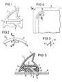
- the sealing profile 1 has a closed sealing lip 3 above a reinforced foot region 2 with a somewhat retracted region 4, in order later to make it easier to contact the surface to be sealed.
- the sealing profile 1 is provided with a further rectangular hollow chamber 5, from the underside of which a slant 6 directed obliquely downwards extends approximately in the center and extends over the entire length of the sealing profile 1.
- mounting elements 10 are inserted at the respective fastening points, as are explained in detail in FIGS. 2 and 3.
- a mounting element 10 consists of a flat, quarter-circular sheet metal strip 11, with expediently rounded corners 12.
- This sheet metal strip 11 has an undercut 13 approximately in the center on its radially inner side, from the center of which radially inwards - with respect to the circular shape of the mounting element 10 - a web-shaped extension 14 which is bent obliquely downwards in accordance with the cross section shown in FIG. 3.
- the quarter-circular strip 11 is surrounded on its underside on both sides of the branching extension 14 by the sealing material and rests here on the partial surfaces 18 and 19 of the underside of the hollow chamber 5. This reliably prevents the mounting element 10 from slipping out of the sealing profile 1 again through the slot 6, for example when the seal is installed, since it is held here by the inwardly projecting lip 20.
Landscapes
- Engineering & Computer Science (AREA)
- Civil Engineering (AREA)
- Structural Engineering (AREA)
- Chemical & Material Sciences (AREA)
- Combustion & Propulsion (AREA)
- Mechanical Engineering (AREA)
- General Engineering & Computer Science (AREA)
- Seal Device For Vehicle (AREA)
- Gasket Seals (AREA)
- Furnace Housings, Linings, Walls, And Ceilings (AREA)
Description
- Die Erfindung betrifft einen Backofen mit einer Türdichtung, die aus einem fortlaufend extrudierten Dichtungsprofil aus hitzebeständigem, elastomerem Material, insbesondere Silikongummi besteht, das den Bereich der Beschickungsöffnung auf mindestens drei Seiten umschließt und eine Dichtlippe und eine im verbreiterten Fußbereich verlaufende Hohlkammer aufweist, in die im Bereich der Ecken der Backofentür oder des Muffelrahmens flache, viertelkreisförmige Halterungselemente mit einem mittig angesetzten und radial nach innen ragenden stegförmigen Ansatz eingesetzt und über diesen Ansatz lösbar in eine entsprechende Öffnung der Tür oder des Muffelrahmens eingehakt sind.
- Eine derartige Dichtung ist aus der GB-A-2106974 bekannt. Dabei ist das Dichtungsprofil jeweils im Eckbereich der Dichtung auf der Unterseite mit einem die Hohlkammer anschneidenden Schlitz versehen, in die entsprechende Halterungselemente eingefädelt und dann in der Hohlkammer mit einem Klebstoff befestigt sind. Über den durch den Schlitz nach außen führenden, zweimal abgewinkelten stegförmigen Ansatz kann die Dichtung dann in eine entsprechende Öffnung des Rahmens eingesetzt werden.
- Bei einem derartigen Halterungselement, bei dem der hakenförmige Ansatz auf einer Längsseite des viertelkreisförmigen Elementes angesetzt ist, besteht jedoch die Gefahr, daß dieses Halterungselement leicht aus dem Schlitz bzw. der Hohlkammer herausrutscht, weswegen der zusätzliche Arbeitsgang eines Einklebens erforderlich ist. Falls man jedoch die andere Montagemöglichkeit wählt, nämlich den Schlitz jeweils kürzer als das Halterungselement zu machen, ist die Einführung des Halterungselementes in die Hohlkammer sehr aufwendig und zeitintensiv.
- Der Erfindung liegt daher die Aufgabe zugrunde, eine Dichtung zu schaffen, die auf einfache Weise ohne Kleben mit den Halterungselementen konfektioniert werden kann und bei der die Gefahr eines Herausrutschens dieser Halterungselemente sicher vermieden ist.
- Zur Lösung dieser Aufgabe ist erfindungemäß vorgesehen, daß das Dichtungsprofil auf seiner Unterseite über seine gesamte Länge einen etwa mittig von der dem Querschnitt des Halterungselementes entsprechenden Hohlkammer schräg nach unten gerichteten Schlitz aufweist, daß das Halterungselement aus einem ebenen, viertelkreisförmigen Blechstreifen mit einem mittig von einem Rückschnitt ausgehenden und über seine gesamte Länge schräg nach unten abgebogenen, stegförmigen Ansatz besteht, und daß das Halterungselement derart über den Schlitz in die Hohlkammer eingesetzt ist, daß das Halterungselement auf seiner Unterseite entlang beider Längskanten vom Dichtungsprofilmaterial umfaßt ist und der Ansatz durch den Schlitz hindurch nach außen ragt. Dabei sind die Halterungselemente auf ihrer Unterseite entlang beider Seitenkanten vom Dichtungsprofil-Material umfaßt.
- Durch den sich über die gesamte Länge des jeweils verwendeten Dichtungsprofils erstreckenden Schlitz können die Halterungselemente somit auf einfache Weise an jeder beliebigen Stelle des Profils eingeschoben werden. Da darüberhinaus der stegförmige Ansatz etwa mittig bezogen auf die Breite des Halterungselementes schräg nach unten wegragt, wird das Halterungselement nach Einsetzen in die Hohlkammer auf der gesamten Unterseite vom Fußbereich des Dichtungsprofils umfaßt, so daß das Halterungselement nicht mehr aus der Dichtung herausrutschen kann.
- Anhand einer schematischen Zeichnung sind Aufbau und Wirkungsweise eines Ausführungsbeispiels nach der Erfindung näher erläutert. Dabei zeigen:
- Fig. 1 einen Querschnitt durch das Dichtungsprofil;
- Fig. 2 eine Aufsicht auf ein Halterungselement;
- Fig. 3 einen Querschnitt entsprechend der Schnittlinie 111-111 nach Fig. 2 durch das Halterungselement;
- Fig. 4 eine Aufsicht auf den Eckbereich der Innenseite einer Backofentür und
- Fig. 5 einen Querschnitt durch ein Dichtungsprofil im eingebauten Zustand entsprechend der Schnittlinie V-V nach Fig. 4.
- Wie aus Fig. 1 zu ersehen ist, weist das Dichtungsprofil 1 oberhalb eines verstärkten Fußbereiches 2 eine geschlossene Dichtlippe 3 mit einem etwas eingezogenen Bereich 4 auf, um sich später an die abzudichtende Fläche leichter anzulegen.
- Im Fußbereich 2 ist das Dichtungsprofil 1 mit einer weiteren rechteckigen Hohlkammer 5 versehen, von deren Unterseite etwa mittig ein schräg nach unten gerichteter Schlitz 6 ausgeht, der sich über die gesamte Länge des Dichtungsprofils 1 erstreckt.
- In die Hohlkammer 5 des Dichtungsprofils 1 werden -wie im einzelnen noch anhand der Fig. 4 und 5 erläutert wird - an den jeweiligen Befestigungspunkten Halterungselemente 10 eingesetzt, wie sie im einzelnen in den Fig. 2 und 3 erläutert sind. Ein derartiges Halterungselement 10 besteht aus einem flachen, viertelkreisförmigen Blechstreifen 11, mit zweckmäßigerweise abgerundeten Ecken 12. Dieser Blechstreifen 11 weist etwa mittig auf seiner radial innenliegenden Seite einen Rückschnitt 13 auf, von dessen Mitte sich radial nach innen - bezüglich der Kreisform des Halterungselementes 10 - ein stegförmiger Ansatz 14 erstreckt, der entsprechend dem in Fig. 3 gezeigten Querschnitt schräg nach unten abgebogen ist.
- Diese Halterungselemente 10 werden dann über den Schlitz 6 in die Hohlkammer 5 eingeschoben und mit dem Ansatz 14 in eine entsprechende Öffnung 15 der Backofentür 16 bzw. der Backofenmuffel eingehakt, wie das aus den Fig. 4 und.5 im einzelnen ersichtlich ist. Wie man dazu aus Fig. 5 ersieht, füllt der viertelkreisförmige Blechstreifen 11 des Halterungselementes 10 die Hohlkammer 5 vollständig aus, während der schräg nach unten geneigte stegförmige Ansatz 14 über den angenähert die gleiche Neigung aufweisenden Schlitz 6 im Fußbereich 2 durch die Öffnung der Backofentür 16 ragt, und damit das Dichtungsprofil 1 stabil in der gewünschten Lage im Bereich einer entsprechenden Ecke hält. Dies insbesondere deshalb, weil derartige Dichtungsprofile 1 im allgemeinen mit Vorspannung eingebaut werden, so daß auf das Halterungselement 10 bzw. den Ansatz 14 stets ein Druck nach innen ausgeübt wird.
- Wie man insbesondere auch aus Fig. 5 ersieht, ist der viertelkreisförmige Streifen 11 auf seiner Unterseite auf beiden Seiten des abzweigenden Ansatzes 14 vom Dichtungsmaterial umgeben und ruht hier auf den Teilflächen 18 und 19 der Unterseite der Hohlkammer 5 auf. Dadurch wird sicher verhindert, daß beispielsweise beim Einbau der Dichtung das Halterungselement 10 durch den Schlitz 6 aus dem Dichtungsprofil 1 wieder herausrutschen kann, da es hier durch die nach innen ragende Lippe 20 festgehalten wird.
- Mit der beschriebenen Ausbildung des Dichtungsprofils und der entsprechenden Halterungselemente ist also ein leichter und dauerhafter Einbau der Dichtung auch unter erheblicher Vorspannung möglich, ohne daß ein Herausfallen der Dichtung zu befürchten ist.
Claims (1)
- Backofen mit einer Türdichtung (1), die aus einem fortlaufend extrudierten Dichtungsprofil (1) aus hitzebeständigem, elastomerem Material, insbesondere Silikongummi, besteht, das den Bereich der Beschickungsöffnung auf mindestens drei Seiten umschließt und eine abragende Dichtlippe (3) und eine im verbreitert ausgebildeten Fußbereich (2) verlaufende Hohlkammer (5) aufweist, in die im Bereich der Ecken der Backofentür (16) oder des Muffelrahmens flache, viertelkreisförmige Halterungselemente (10) mit einem mittig angesetzten und radial nach innen ragenden stegförmigen Ansatz (14) eingesetzt und über diesen Ansatz (14) lösbar in entsprechende Öffnungen (15) der Tür (16) oder des Muffelrahmens eingehakt sind, dadurch gekennzeichnet, daß das Dichtungsprofil (1) auf seiner Unterseite über seine gesamte Länge einen etwa mittig von der dem Querschnitt des Halterungselementes (10) entsprechenden Hohlkammer (5) schräg nach unten gerichteten Schlitz (6) aufweist, daß das Halterungselement (10) aus einem ebenen, viertelkreisförmigen Blechstreifen (11) mit einem mittig von einem Rückschnitt (13) ausgehenden und über seine gesamte Länge schräg nach unten abgebogenen, stegförmigen Ansatz (14) besteht, und daß das Halterungselement (10) derart über den Schlitz (6) in die Hohlkammer (5) eingesetzt ist, daß das Halterungselement (10) auf seiner Unterseite entlang beider Längskanten vom Dichtungsprofilmaterial (18, 19) umfaßt ist und der Ansatz (14) durch den Schlitz (6) hindurch nach außen ragt.
Applications Claiming Priority (2)
| Application Number | Priority Date | Filing Date | Title |
|---|---|---|---|
| DE19843439336 DE3439336A1 (de) | 1984-10-26 | 1984-10-26 | Tuerdichtung fuer einen backofen |
| DE3439336 | 1984-10-26 |
Publications (3)
| Publication Number | Publication Date |
|---|---|
| EP0180147A2 EP0180147A2 (de) | 1986-05-07 |
| EP0180147A3 EP0180147A3 (en) | 1988-01-20 |
| EP0180147B1 true EP0180147B1 (de) | 1990-01-10 |
Family
ID=6248878
Family Applications (1)
| Application Number | Title | Priority Date | Filing Date |
|---|---|---|---|
| EP85113508A Expired - Lifetime EP0180147B1 (de) | 1984-10-26 | 1985-10-24 | Türdichtung für einen Backofen |
Country Status (3)
| Country | Link |
|---|---|
| EP (1) | EP0180147B1 (de) |
| DE (2) | DE3439336A1 (de) |
| ES (1) | ES288928Y (de) |
Families Citing this family (11)
| Publication number | Priority date | Publication date | Assignee | Title |
|---|---|---|---|---|
| FR2642809B1 (fr) * | 1989-01-13 | 1992-03-13 | Smadja Jean Claude | Dispositif d'etancheite notamment pour vehicules automobiles comportant au moins une piece profilee tubulaire |
| DE9217581U1 (de) * | 1992-12-23 | 1993-04-08 | Brügmann Frisoplast GmbH, 4600 Dortmund | Dichtungsprofil für Türen |
| FR2730541B1 (fr) * | 1995-02-10 | 1997-05-09 | Gessil | Ensemble de jointoiement a plat |
| DE29719773U1 (de) * | 1997-11-07 | 1997-12-18 | Rehau Ag + Co, 95111 Rehau | Dichtprofil |
| DE60016468T2 (de) * | 2000-02-22 | 2005-12-29 | G.I.A.T. S.P.A., Peschiera Borromeo | Türrahmen mit backofendichtung |
| DE10162057B4 (de) * | 2001-12-17 | 2004-04-15 | Dorma Gmbh + Co. Kg | Abschluss für ein Seitenteil oder eine Tür einer sanitären Einrichtung |
| DE102004032931A1 (de) * | 2004-07-07 | 2006-02-02 | BSH Bosch und Siemens Hausgeräte GmbH | Backofen mit einer Backofentürdichtung |
| DE202006009314U1 (de) * | 2006-06-12 | 2006-08-24 | Rehau Ag + Co. | Versteifungselement für Hohlkammerdichtungsprofile |
| WO2008003708A2 (en) * | 2006-07-04 | 2008-01-10 | Arcelik Anonim Sirketi | An oven |
| DE202016107346U1 (de) | 2016-12-23 | 2018-03-26 | Rehau Ag + Co | Dichtungsanordnung |
| CN110821361B (zh) * | 2018-08-08 | 2025-02-18 | 宁波方太厨具有限公司 | 一种蒸微一体机的门体结构 |
Citations (1)
| Publication number | Priority date | Publication date | Assignee | Title |
|---|---|---|---|---|
| EP0096745A2 (de) * | 1982-06-16 | 1983-12-28 | Metzeler Kautschuk Gmbh | Dichtungsprofil aus hitzebeständigem, elastomerem Material |
Family Cites Families (5)
| Publication number | Priority date | Publication date | Assignee | Title |
|---|---|---|---|---|
| GB963227A (en) * | 1961-04-24 | 1964-07-08 | Gen Motors Corp | Door seal-strip |
| DE3047380A1 (de) * | 1980-12-16 | 1982-07-08 | Bosch-Siemens Hausgeräte GmbH, 7000 Stuttgart | Backofen |
| GB2106974B (en) * | 1981-10-06 | 1985-08-29 | Silicone Altimex Ltd | Door seal |
| GB2113827B (en) * | 1982-01-23 | 1985-01-23 | Silicone Fabrications Limited | Stretch gaskets |
| FR2553170B1 (fr) * | 1983-10-11 | 1987-10-30 | Gerland | Joint d'etancheite en elastomere constitue d'une seule longueur de profile |
-
1984
- 1984-10-26 DE DE19843439336 patent/DE3439336A1/de not_active Withdrawn
-
1985
- 1985-09-04 ES ES1985288928U patent/ES288928Y/es not_active Expired
- 1985-10-24 EP EP85113508A patent/EP0180147B1/de not_active Expired - Lifetime
- 1985-10-24 DE DE8585113508T patent/DE3575341D1/de not_active Expired - Lifetime
Patent Citations (1)
| Publication number | Priority date | Publication date | Assignee | Title |
|---|---|---|---|---|
| EP0096745A2 (de) * | 1982-06-16 | 1983-12-28 | Metzeler Kautschuk Gmbh | Dichtungsprofil aus hitzebeständigem, elastomerem Material |
Also Published As
| Publication number | Publication date |
|---|---|
| ES288928Y (es) | 1986-10-01 |
| ES288928U (es) | 1986-01-16 |
| DE3439336A1 (de) | 1986-05-07 |
| DE3575341D1 (de) | 1990-02-15 |
| EP0180147A2 (de) | 1986-05-07 |
| EP0180147A3 (en) | 1988-01-20 |
Similar Documents
| Publication | Publication Date | Title |
|---|---|---|
| EP0180147B1 (de) | Türdichtung für einen Backofen | |
| DE2523244A1 (de) | Bausatz fuer gebaeude | |
| DE4228874C2 (de) | Strangförmiges Dichtungsprofil | |
| EP0199025A1 (de) | Befestigungsanordnung für Lamellen einer Jalousie | |
| DE69318421T2 (de) | Fenstersprosse | |
| DE3222671C2 (de) | Anordnung zur Abdichtung einer eine Bachofenmuffel verschließenden Tür | |
| DE2606614C3 (de) | Rahmen für einen Fenster- oder Türflügel | |
| DE3739068A1 (de) | Halterung fuer die loesbare abdeckung einer oeffnung in einer fliesenwand | |
| DE3439335A1 (de) | Tuerdichtung fuer einen backofen | |
| DE8431542U1 (de) | Tuerdichtung fuer einen backofen | |
| EP0185201B1 (de) | Schubkasten aus Kunststoff | |
| DE2501710C3 (de) | Dichtungsleiste | |
| DE2217116C2 (de) | Spannvorrichtung für Deckenbespannungen | |
| EP2604782B1 (de) | Fensterflügelprofil für die Montage von Klotzbrücken oder dergleichen | |
| DE2119184B2 (de) | Scheibenhalterung eines Fensters o.dgl | |
| DD294757A5 (de) | Einrichtung zur verklotzung von scheiben in tuer- oder fensterrahmen | |
| DE1913087U (de) | Bordprofil mit fuehrungsschiene fuer metall-fensterbaenke. | |
| DE29605731U1 (de) | Sanitärkeramik | |
| DE1940691U (de) | Einfassung aus gummi oder gummiaehnlichem material zum befestigen einer scheibe od. dgl. in einem rahmen. | |
| EP0581930B1 (de) | Bordürenprofil | |
| DE8431541U1 (de) | Türdichtung für einen Backofen | |
| DE3525538A1 (de) | Mit einer dichtung versehene tuer, insbesondere doppelseitig verkleidete, waermeisolierte tuer fuer kuehlschraenke und dgl. | |
| DE3905896A1 (de) | Klammer zur halterung von verkleidungsplatten an fassadenwaenden | |
| DE2243021C3 (de) | Befestigung einer feststehenden Zarge für Türen oder Fenster an Tragschienen | |
| DE8811065U1 (de) | Fenster- oder Türflügel |
Legal Events
| Date | Code | Title | Description |
|---|---|---|---|
| PUAI | Public reference made under article 153(3) epc to a published international application that has entered the european phase |
Free format text: ORIGINAL CODE: 0009012 |
|
| 17P | Request for examination filed |
Effective date: 19851024 |
|
| AK | Designated contracting states |
Kind code of ref document: A2 Designated state(s): DE FR GB IT NL SE |
|
| PUAL | Search report despatched |
Free format text: ORIGINAL CODE: 0009013 |
|
| AK | Designated contracting states |
Kind code of ref document: A3 Designated state(s): DE FR GB IT NL SE |
|
| RAP1 | Party data changed (applicant data changed or rights of an application transferred) |
Owner name: METZELER GESELLSCHAFT MIT BESCHRAENKTER HAFTUNG |
|
| 17Q | First examination report despatched |
Effective date: 19890118 |
|
| GRAA | (expected) grant |
Free format text: ORIGINAL CODE: 0009210 |
|
| AK | Designated contracting states |
Kind code of ref document: B1 Designated state(s): DE FR GB IT NL SE |
|
| REF | Corresponds to: |
Ref document number: 3575341 Country of ref document: DE Date of ref document: 19900215 |
|
| ITF | It: translation for a ep patent filed | ||
| ET | Fr: translation filed | ||
| GBT | Gb: translation of ep patent filed (gb section 77(6)(a)/1977) | ||
| PLBE | No opposition filed within time limit |
Free format text: ORIGINAL CODE: 0009261 |
|
| STAA | Information on the status of an ep patent application or granted ep patent |
Free format text: STATUS: NO OPPOSITION FILED WITHIN TIME LIMIT |
|
| 26N | No opposition filed | ||
| PGFP | Annual fee paid to national office [announced via postgrant information from national office to epo] |
Ref country code: GB Payment date: 19911011 Year of fee payment: 7 |
|
| PGFP | Annual fee paid to national office [announced via postgrant information from national office to epo] |
Ref country code: FR Payment date: 19920723 Year of fee payment: 8 |
|
| PGFP | Annual fee paid to national office [announced via postgrant information from national office to epo] |
Ref country code: SE Payment date: 19920930 Year of fee payment: 8 |
|
| PG25 | Lapsed in a contracting state [announced via postgrant information from national office to epo] |
Ref country code: GB Effective date: 19921024 |
|
| ITTA | It: last paid annual fee | ||
| PGFP | Annual fee paid to national office [announced via postgrant information from national office to epo] |
Ref country code: NL Payment date: 19921031 Year of fee payment: 8 |
|
| PGFP | Annual fee paid to national office [announced via postgrant information from national office to epo] |
Ref country code: DE Payment date: 19921104 Year of fee payment: 8 |
|
| GBPC | Gb: european patent ceased through non-payment of renewal fee |
Effective date: 19921024 |
|
| PG25 | Lapsed in a contracting state [announced via postgrant information from national office to epo] |
Ref country code: SE Effective date: 19931025 |
|
| PG25 | Lapsed in a contracting state [announced via postgrant information from national office to epo] |
Ref country code: NL Effective date: 19940501 |
|
| NLV4 | Nl: lapsed or anulled due to non-payment of the annual fee | ||
| PG25 | Lapsed in a contracting state [announced via postgrant information from national office to epo] |
Ref country code: FR Effective date: 19940630 |
|
| PG25 | Lapsed in a contracting state [announced via postgrant information from national office to epo] |
Ref country code: DE Effective date: 19940701 |
|
| REG | Reference to a national code |
Ref country code: FR Ref legal event code: ST |
|
| EUG | Se: european patent has lapsed |
Ref document number: 85113508.7 Effective date: 19940510 |