EP0180176B2 - Ventilateur - Google Patents
Ventilateur Download PDFInfo
- Publication number
- EP0180176B2 EP0180176B2 EP85113684A EP85113684A EP0180176B2 EP 0180176 B2 EP0180176 B2 EP 0180176B2 EP 85113684 A EP85113684 A EP 85113684A EP 85113684 A EP85113684 A EP 85113684A EP 0180176 B2 EP0180176 B2 EP 0180176B2
- Authority
- EP
- European Patent Office
- Prior art keywords
- casing jacket
- hub
- inner face
- rotor
- jacket
- Prior art date
- Legal status (The legal status is an assumption and is not a legal conclusion. Google has not performed a legal analysis and makes no representation as to the accuracy of the status listed.)
- Expired - Lifetime
Links
- 230000004323 axial length Effects 0.000 claims description 4
- 230000007423 decrease Effects 0.000 description 1
- 238000010586 diagram Methods 0.000 description 1
- 238000009434 installation Methods 0.000 description 1
- 230000004048 modification Effects 0.000 description 1
- 238000012986 modification Methods 0.000 description 1
Images
Classifications
-
- F—MECHANICAL ENGINEERING; LIGHTING; HEATING; WEAPONS; BLASTING
- F04—POSITIVE - DISPLACEMENT MACHINES FOR LIQUIDS; PUMPS FOR LIQUIDS OR ELASTIC FLUIDS
- F04D—NON-POSITIVE-DISPLACEMENT PUMPS
- F04D29/00—Details, component parts, or accessories
- F04D29/40—Casings; Connections of working fluid
- F04D29/52—Casings; Connections of working fluid for axial pumps
- F04D29/54—Fluid-guiding means, e.g. diffusers
- F04D29/541—Specially adapted for elastic fluid pumps
- F04D29/545—Ducts
-
- F—MECHANICAL ENGINEERING; LIGHTING; HEATING; WEAPONS; BLASTING
- F04—POSITIVE - DISPLACEMENT MACHINES FOR LIQUIDS; PUMPS FOR LIQUIDS OR ELASTIC FLUIDS
- F04D—NON-POSITIVE-DISPLACEMENT PUMPS
- F04D25/00—Pumping installations or systems
- F04D25/02—Units comprising pumps and their driving means
- F04D25/06—Units comprising pumps and their driving means the pump being electrically driven
- F04D25/0606—Units comprising pumps and their driving means the pump being electrically driven the electric motor being specially adapted for integration in the pump
- F04D25/0613—Units comprising pumps and their driving means the pump being electrically driven the electric motor being specially adapted for integration in the pump the electric motor being of the inside-out type, i.e. the rotor is arranged radially outside a central stator
Definitions
- the invention relates to a fan with the features of the preamble of claim 1.
- Such a fan is known from DE-A-1 628 363.
- the cross section of its flow channel should be as constant as possible in the region of the conically widening hub forming the inner surface of the fault channel.
- the divergence angle of the hub should even be a few degrees larger than the divergence angle of the housing inner wall forming the outer surface of the flow channel.
- a fan is known with two square flanges on both ends of the housing shell.
- the inner surface of the housing shell has a constant axially constant minimum diameter, apart from bevels in the area of the flange corners, at which the diameter increases outwards. Between bevels adjacent in the circumferential direction, the inner surface has its minimum diameter.
- the outer surface of the hub widens conically from the so-called end over about the first third of the axial length of the housing shell and then has a section of almost constant maximum diameter, which is then followed by a further section of constant diameter, which is, however, slightly smaller than the maximum diameter .
- Fans of this type are used as built-in fans and are available for this purpose in dimensions of 3 to 20 cm (centimeters) pipe diameter. With such fans, the space available for the required internals is limited by the interior of the pipe section and this is made as short as possible in the interest of narrow installation conditions. In order to adapt the flow characteristics to the respective requirements, such fans can only be changed within the available outer contour.
- the object of the invention is to modify such a fan within the given outer contour so that it has a larger differential pressure generated between suction and pressure side.
- the invention enables one to change the fan characteristics in the sense of the task simply by inserting a ring. This is very advantageous for production, since fans of the type mentioned at the outset are very advantageous for production, because the same components, namely the same pipe section and the same motor, can be used for fans with a high flow rate and for fans with high pressure , you only have to insert the ring and adjust the blades in the case of the pressure fan.
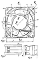
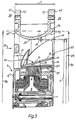
- 1 designates a housing jacket designed as a piece of pipe, the length of which, according to double arrow 2, is smaller than its smallest diameter, according to double arrow 3.
- an electric drive motor is designated, which is completely coaxially mounted within the housing jacket 1.
- the drive motor 4 is an external rotor motor.
- the drive motor is fastened to the housing jacket 1 with four spokes 5, 6, 7, 8 distributed over the circumference.
- the spokes extend along the one end, for example the so-called end of the housing jacket, from the housing jacket to a bearing disk 11.
- This bearing disk 11 belongs to the generally designated 9 stator of the electric drive motor.
- 10 denotes the rotor of the motor 4, which is cup-shaped and surrounds the stator as close as possible to the spokes 5, 6, 7, 8 or to the bearing disk 11.
- a ring 12 is placed on the rotor 10 so as to prevent rotation, which has an outer surface 13 has, which widens conically in the direction of flow according to arrow 24.
- the ring 12 is fitted in a form-fitting manner on the pot-shaped rotor 10.
- the ring 12 consists of an inner wall 21 which fits the rotor 10 in a form-fitting manner and an outer wall 22 which is at an angle to and on the inner wall is fixed so that between the two walls 21 and 22 a wedge-shaped annular gap 26 open to the pressure side 25 is recessed.
- This wedge-shaped annular gap 26 can also be closed or filled. It is essential that the outer surface 13, which delimits an annular flow channel 14 towards the inside, widens axially continuously conically in the direction of flow, with an angle 28 of 5 to 45 °, preferably 30 °, as in the exemplary embodiment shown.
- the annular flow channel 14 is delimited on the outside by the inner surface 15 of the housing shell and on the inside by the outer surface 13 of the ring 12.
- the rotor 10 together with the ring 12 forms a hub 27.
- a total of five vanes 16 to 20 are distributed over the outer surface 13 of the hub , which form a wing ring and are attached to the ring 12.
- the hub 27 with the vanes 16 to 20 forms a fan wheel 23.
- the vanes 16 to 20 extend over the entire cross-section of the flow channel 14 with a tolerance distance according to the double arrow 30 to the inner wall 15 of the housing shell 1 and with a somewhat greater distance according to the double arrow 31 to the spokes 5 to 8.
- the inner surface 15 of the housing shell 1 has a constriction 35 with the smallest diameter 29 in the central region in relation to the axial length and widens to the pressure side 25 to a larger diameter 33 or 37 with intermediate values and to the suction side 36 to a larger diameter 32 or 38 intermediate values.
- the diameter 29 is smaller than the diameters 32, 33, 37 and 38 and all intermediate values.
- the diameters 32 and 33 on the one hand and the diameters 37 and 38 on the other hand are approximately the same size.
- a flange 40, 41 with a square outer contour is provided at both ends of the housing shell 1.
- the two flanges 40, 41 are congruent, so that the flange 40 in Figure 1 is covered by the flange 41 visible there.
- the square outer contour of the flanges closely surrounds the housing casing 1 at the ends, so that in the narrowest area, for example in area 43, between adjacent flange corners, for example flange corners 44, 45, the material thickness of the flange according to double arrow 46 is not significantly stronger than the material thickness of the housing shell, compare Figure 1 and Figure 4.
- All parts of the fan are housed within the housing shell 1 and the entire fan including the flanges is accommodated in a square cylinder, the base of which is formed by the square shape of a flange and the height of the double arrow 2, i.e. the length of the housing shell 1, corresponds.
- the flow channel 14 is formed by chamfers in the region of the flange corners and is radially expanded at the chamfers.
- the flange corners 44, 45 associated bevels are designated 50, 51.
- the bevels assigned to the flange corners 52, 53 are designated 54, 55.
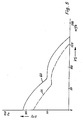
- the pressure increase Pf achieved on the pressure side is plotted on the vertical axis and the volume flow VS of the conveying air is plotted on the horizontal axis.
- the curve 60 drawn in solid lines shows the values measured for an axial fan according to FIGS. 1 to 4.
- the dashed curve 61 shows measured values for a comparable sized axial fan, the hub outer surface of which is the outer surface 57 of the rotor 10, which has approximately the same diameter everywhere. From the characteristic diagram it can be seen that the pressure increase on the pressure side compared to the prior art is achieved without Loss in the volume flow of the conveying air. The comparison of the characteristic curves shows that the invention as a whole also increases the conveying capacity
- the ring 12 can also be part of the rotor 10.
Landscapes
- Engineering & Computer Science (AREA)
- Mechanical Engineering (AREA)
- General Engineering & Computer Science (AREA)
- Structures Of Non-Positive Displacement Pumps (AREA)
Claims (6)
- Ventilateur- comprenant une surface latérale de carter (1) réalisée sous la forme d'une pièce tubulaire,- comprenant un moteur électrique d'entraînement (4) qui est monté coaxialement à l'intérieur de la surface latérale du carter,- comprenant des rayons (5, 6, 7, 8) destinés à fixer le stator (9) du moteur d'entraînement (4) à la surface latérale (1) du carter et s'étendant à l'intérieur de la surface latérale (1) du carter à l'extrémité de la surface latérale (1) du carter qui est située du côté de l'aspiration,- comprenant une roue de ventilateur (23) comportant un moyeu (27) qui porte une couronne de pales (16 à 20) et présente une surface extérieure (13) qui s'élargit continûment en forme de cône sur toute sa longueur dans le sens axial et dans la direction de l'écoulement (24), et sur laquelle sont fixées les pales (16 à 20) de la couronne de pales,- comprenant un canal d'écoulement (14) qui est délimité extérieurement par la surface intérieure (15) de la surface latérale (1) du carter et intérieurement par la surface extérieure (13) du moyeu (27),- le moteur d'entraînement (4) et la roue de ventilateur (23) s'étendant de manière coaxiale et complètement à l'intérieur de la surface latérale (1) du carter,- le diamètre (32) de la surface intérieure (15) de la surface latérale (1) du carter à l'extrémité qui est située du côté de l'aspiration étant à peu près égal au diamètre (33) de cette surface intérieure à l'extrémité qui est située du côté du refoulement,- la surface intérieure (15) de la surface latérale (1) du carter formant un étranglement (35) qui s'étend sur l'ensemble du contour balayé par la roue de ventilateur (23),- la surface intérieure (15) de la surface latérale (1) du carter se raccordant à l'étranglement sur toute sa périphérie en s'élargissant du côté de l'aspiration et du côté du refoulement pour présenter un diamètre plus important (32, 33),
caractérisé par le fait que :- la surface intérieure (15) de la surface latérale (1) du carter présente son plus petit diamètre (29) dans sa zone centrale rapportée à la longueur de la roue de ventilateur (23) dans le sens axial, de sorte que l'étranglement (35) ainsi formé est situé entre les extrémités du moyeu,- et le canal d'écoulement (14) qui est formé entre le moyeu (27) et la surface latérale (1) du carter s'élargit depuis l'étranglement (35) vers l'extrémité qui est située du côté de l'aspiration et vers l'extrémité qui est située du côté du refoulement dans la région de l'extrémité de la surface latérale du carter. - Ventilateur selon la revendication 1, caractérisé par le fait :
que le moyeu (27) présente un rotor (10) qui est sensiblement cylindrique de révolution,
qu'une bague fixée au rotor s'étend complètement à l'intérieur de la pièce tubulaire (1) et présente la surface extérieure (13) qui s'élargit continûment en forme de cône dans la direction de l'écoulement et qui délimite le canal d'écoulement (14) vers l'intérieur. - Ventilateur selon l'une des revendications précédentes, caractérisé par le fait :
que la bague (12) se compose d'une paroi intérieure (21) qui s'ajuste sur le rotor (10) avec conjugaison des formes, et d'une paroi extérieure (22) qui est oblique par rapport à elle et qui forme la surface extérieure (13), et :
qu'un interstice annulaire (26) en forme de coin et ouvert vers le côté du refoulement (25) est ménagé entre les deux parois (21, 22). - Ventilateur selon l'une des revendications précédentes, caractérisé par le fait que les pales (16 à 20) s'étendent sur l'ensemble de la section transversale du canal d'écoulement (14) en présentant une distance correspondant aux tolérances par rapport à la paroi intérieure de la pièce tubulaire (1) et une distance légèrement supérieure par rapport aux rayons (5 à 8).
- Ventilateur selon l'une des revendications précédentes, caractérisé par le fait :
qu'il est prévu, à l'une des extrémités de la surface latérale (1) du carter, ou aux deux, une bride (40, 41) dont le contour extérieur est carré et qui s'étend à l'intérieur de la longueur axiale de la pièce tubulaire, et :
que la surface intérieure (15) de la surface latérale du carter présente des chanfreins (50, 51) dans la région des coins (44, 45) des brides, et qu'elle est élargie radialement sur les chanfreins. - Ventilateur selon l'une des revendications précédentes, caractérisé par le fait :
que le moteur d'entraînement (4) est un moteur à induit extérieur dont le rotor est la carcasse qui entoure le stator.
Applications Claiming Priority (2)
| Application Number | Priority Date | Filing Date | Title |
|---|---|---|---|
| DE19843439539 DE3439539A1 (de) | 1984-10-29 | 1984-10-29 | Ventilator |
| DE3439539 | 1984-10-29 |
Publications (3)
| Publication Number | Publication Date |
|---|---|
| EP0180176A1 EP0180176A1 (fr) | 1986-05-07 |
| EP0180176B1 EP0180176B1 (fr) | 1990-01-03 |
| EP0180176B2 true EP0180176B2 (fr) | 1995-05-03 |
Family
ID=6249011
Family Applications (1)
| Application Number | Title | Priority Date | Filing Date |
|---|---|---|---|
| EP85113684A Expired - Lifetime EP0180176B2 (fr) | 1984-10-29 | 1985-10-28 | Ventilateur |
Country Status (2)
| Country | Link |
|---|---|
| EP (1) | EP0180176B2 (fr) |
| DE (2) | DE3439539A1 (fr) |
Families Citing this family (5)
| Publication number | Priority date | Publication date | Assignee | Title |
|---|---|---|---|---|
| JPH0749800B2 (ja) * | 1988-03-11 | 1995-05-31 | 三菱電機株式会社 | 軸流送風機 |
| EP0446316B2 (fr) * | 1989-09-29 | 2001-12-05 | Micronel AG | Petit ventilateur |
| DE4127134B4 (de) * | 1991-08-15 | 2004-07-08 | Papst Licensing Gmbh & Co. Kg | Diagonallüfter |
| RU2132972C1 (ru) * | 1997-12-16 | 1999-07-10 | Караджи Вячеслав Георгиевич | Осевой вентилятор с низким уровнем шума |
| GB9726521D0 (en) | 1997-12-17 | 1998-02-11 | Sturmey Archer Ltd | Improvements in or relating to multi-speed hub gears |
Family Cites Families (9)
| Publication number | Priority date | Publication date | Assignee | Title |
|---|---|---|---|---|
| US2536130A (en) * | 1946-05-21 | 1951-01-02 | Hartzell Industries | Air handling apparatus |
| GB858640A (en) * | 1958-10-07 | 1961-01-11 | Jacobus Constant Van Rijn | Ventilating motor and fan |
| DE1728338B2 (de) * | 1963-01-14 | 1973-02-15 | Papst, Hermann, 7742 St Georgen | Axialventilator |
| CH611983A5 (fr) * | 1974-11-18 | 1979-06-29 | Papst Motoren Kg | |
| CH635900A5 (de) * | 1978-02-15 | 1983-04-29 | Papst Motoren Kg | Axial kompaktes geblaese. |
| DE7932582U1 (de) * | 1979-11-17 | 1980-03-13 | Papst-Motoren Kg, 7742 St Georgen | Einbauventilator |
| FR2497883B1 (fr) * | 1981-01-09 | 1985-12-13 | Etri Sa | Ventilateur electrique axial de type plat |
| JPS5865999A (ja) * | 1981-10-12 | 1983-04-19 | Nissan Motor Co Ltd | 斜流型フアン |
| DE3227698A1 (de) * | 1982-07-24 | 1984-01-26 | Papst-Motoren GmbH & Co KG, 7742 St Georgen | Axialventilator |
-
1984
- 1984-10-29 DE DE19843439539 patent/DE3439539A1/de not_active Withdrawn
-
1985
- 1985-10-28 DE DE8585113684T patent/DE3575181D1/de not_active Expired - Lifetime
- 1985-10-28 EP EP85113684A patent/EP0180176B2/fr not_active Expired - Lifetime
Also Published As
| Publication number | Publication date |
|---|---|
| EP0180176B1 (fr) | 1990-01-03 |
| DE3575181D1 (en) | 1990-02-08 |
| EP0180176A1 (fr) | 1986-05-07 |
| DE3439539A1 (de) | 1986-05-07 |
Similar Documents
| Publication | Publication Date | Title |
|---|---|---|
| DE2940650C2 (fr) | ||
| DE3227698C2 (fr) | ||
| DE69835123T2 (de) | Wechselstromgenrator mit verbesserten Mitteln zur Kühlung, insbesondere für ein Kraftfahrzeug | |
| DE2639914C2 (fr) | ||
| DE2257509A1 (de) | Radialgeblaese | |
| DE10204037C5 (de) | Radialgebläse mit Elektromotor | |
| EP2691655A1 (fr) | Ventilateur diagonal | |
| DE2338395C3 (de) | Kraftstoffförderpumpe, insbesondere für Kraftfahrzeuge | |
| DE2042356A1 (de) | Seitenkanalverdichter | |
| DE29516599U1 (de) | Reibungsvakuumpumpe mit Zwischeneinlaß | |
| WO2006136585A1 (fr) | Rotor comportant une roue de ventilateur destine a un moteur electrique a commutation electronique | |
| DE10145786A1 (de) | Windkraftturbine mit einem die Rotorblätter umgebenden Mantelgehäuse | |
| EP0180176B1 (fr) | Ventilateur | |
| DE2533184A1 (de) | Elektromotor mit axialspalt | |
| DE1403853A1 (de) | Rotierende Einrichtung zum Bewegen eines fluessigen oder gasfoermigen Mediums | |
| DE4141106C2 (de) | Radialgebläse | |
| DE69401747T2 (de) | Lüftergehäuse | |
| DE2400496A1 (de) | Umfangsgeblaese | |
| DE2458014C3 (de) | Stator eines Mehrstufen-Radialverdichters | |
| DE3612249A1 (de) | Ventilator | |
| DE8431713U1 (de) | Ventilator | |
| EP0052251B1 (fr) | Compresseur à canaux latéraux | |
| DE3022477A1 (de) | Einbauventilator | |
| DE60211661T2 (de) | Luftlaufrad und gehäuse für ein solches laufrad | |
| DE1083481B (de) | Laufrad fuer Kreiselradmaschinen |
Legal Events
| Date | Code | Title | Description |
|---|---|---|---|
| PUAI | Public reference made under article 153(3) epc to a published international application that has entered the european phase |
Free format text: ORIGINAL CODE: 0009012 |
|
| AK | Designated contracting states |
Kind code of ref document: A1 Designated state(s): AT BE CH DE FR GB IT LI LU NL SE |
|
| RBV | Designated contracting states (corrected) |
Designated state(s): DE FR GB IT |
|
| 17P | Request for examination filed |
Effective date: 19860611 |
|
| 17Q | First examination report despatched |
Effective date: 19870205 |
|
| GRAA | (expected) grant |
Free format text: ORIGINAL CODE: 0009210 |
|
| AK | Designated contracting states |
Kind code of ref document: B1 Designated state(s): DE FR GB IT |
|
| PG25 | Lapsed in a contracting state [announced via postgrant information from national office to epo] |
Ref country code: IT Free format text: LAPSE BECAUSE OF FAILURE TO SUBMIT A TRANSLATION OF THE DESCRIPTION OR TO PAY THE FEE WITHIN THE PRESCRIBED TIME-LIMIT;WARNING: LAPSES OF ITALIAN PATENTS WITH EFFECTIVE DATE BEFORE 2007 MAY HAVE OCCURRED AT ANY TIME BEFORE 2007. THE CORRECT EFFECTIVE DATE MAY BE DIFFERENT FROM THE ONE RECORDED. Effective date: 19900103 Ref country code: FR Free format text: LAPSE BECAUSE OF FAILURE TO SUBMIT A TRANSLATION OF THE DESCRIPTION OR TO PAY THE FEE WITHIN THE PRESCRIBED TIME-LIMIT Effective date: 19900103 |
|
| REF | Corresponds to: |
Ref document number: 3575181 Country of ref document: DE Date of ref document: 19900208 |
|
| GBT | Gb: translation of ep patent filed (gb section 77(6)(a)/1977) | ||
| EN | Fr: translation not filed | ||
| PLBI | Opposition filed |
Free format text: ORIGINAL CODE: 0009260 |
|
| 26 | Opposition filed |
Opponent name: EBM ELEKTROBAU MULFINGEN GMBH & CO. Effective date: 19901002 |
|
| REG | Reference to a national code |
Ref country code: GB Ref legal event code: 711B |
|
| REG | Reference to a national code |
Ref country code: GB Ref legal event code: 711G |
|
| RAP2 | Party data changed (patent owner data changed or rights of a patent transferred) |
Owner name: PAPST LICENSING GMBH |
|
| PUAH | Patent maintained in amended form |
Free format text: ORIGINAL CODE: 0009272 |
|
| STAA | Information on the status of an ep patent application or granted ep patent |
Free format text: STATUS: PATENT MAINTAINED AS AMENDED |
|
| REG | Reference to a national code |
Ref country code: GB Ref legal event code: 732E |
|
| 27A | Patent maintained in amended form |
Effective date: 19950503 |
|
| AK | Designated contracting states |
Kind code of ref document: B2 Designated state(s): DE FR GB IT |
|
| GBTA | Gb: translation of amended ep patent filed (gb section 77(6)(b)/1977) |
Effective date: 19950809 |
|
| EN3 | Fr: translation not filed ** decision concerning opposition | ||
| PGFP | Annual fee paid to national office [announced via postgrant information from national office to epo] |
Ref country code: DE Payment date: 19961223 Year of fee payment: 12 |
|
| PG25 | Lapsed in a contracting state [announced via postgrant information from national office to epo] |
Ref country code: DE Free format text: LAPSE BECAUSE OF NON-PAYMENT OF DUE FEES Effective date: 19980701 |
|
| REG | Reference to a national code |
Ref country code: GB Ref legal event code: IF02 |
|
| PGFP | Annual fee paid to national office [announced via postgrant information from national office to epo] |
Ref country code: GB Payment date: 20031010 Year of fee payment: 19 |
|
| PG25 | Lapsed in a contracting state [announced via postgrant information from national office to epo] |
Ref country code: GB Free format text: LAPSE BECAUSE OF NON-PAYMENT OF DUE FEES Effective date: 20041028 |
|
| GBPC | Gb: european patent ceased through non-payment of renewal fee |
Effective date: 20041028 |
|
| APAH | Appeal reference modified |
Free format text: ORIGINAL CODE: EPIDOSCREFNO |