EP0180186A1 - Automatische Fokussierschaltung für Videokameras - Google Patents
Automatische Fokussierschaltung für Videokameras Download PDFInfo
- Publication number
- EP0180186A1 EP0180186A1 EP85113714A EP85113714A EP0180186A1 EP 0180186 A1 EP0180186 A1 EP 0180186A1 EP 85113714 A EP85113714 A EP 85113714A EP 85113714 A EP85113714 A EP 85113714A EP 0180186 A1 EP0180186 A1 EP 0180186A1
- Authority
- EP
- European Patent Office
- Prior art keywords
- circuit
- signal
- output
- auto focus
- absolute value
- Prior art date
- Legal status (The legal status is an assumption and is not a legal conclusion. Google has not performed a legal analysis and makes no representation as to the accuracy of the status listed.)
- Granted
Links
- 238000005070 sampling Methods 0.000 claims abstract description 17
- 230000015654 memory Effects 0.000 claims description 35
- 238000000926 separation method Methods 0.000 claims description 7
- 238000012935 Averaging Methods 0.000 abstract description 5
- 230000008859 change Effects 0.000 description 7
- 238000006243 chemical reaction Methods 0.000 description 7
- 238000000034 method Methods 0.000 description 6
- 238000010586 diagram Methods 0.000 description 4
- 230000003247 decreasing effect Effects 0.000 description 2
- 230000007613 environmental effect Effects 0.000 description 2
- 230000006872 improvement Effects 0.000 description 2
- 230000007423 decrease Effects 0.000 description 1
- 230000001419 dependent effect Effects 0.000 description 1
- 238000001514 detection method Methods 0.000 description 1
- 230000006870 function Effects 0.000 description 1
- 238000005259 measurement Methods 0.000 description 1
- 230000004044 response Effects 0.000 description 1
- 229920006395 saturated elastomer Polymers 0.000 description 1
Images
Classifications
-
- H—ELECTRICITY
- H04—ELECTRIC COMMUNICATION TECHNIQUE
- H04N—PICTORIAL COMMUNICATION, e.g. TELEVISION
- H04N23/00—Cameras or camera modules comprising electronic image sensors; Control thereof
- H04N23/60—Control of cameras or camera modules
- H04N23/67—Focus control based on electronic image sensor signals
- H04N23/673—Focus control based on electronic image sensor signals based on contrast or high frequency components of image signals, e.g. hill climbing method
-
- H—ELECTRICITY
- H03—ELECTRONIC CIRCUITRY
- H03M—CODING; DECODING; CODE CONVERSION IN GENERAL
- H03M1/00—Analogue/digital conversion; Digital/analogue conversion
- H03M1/12—Analogue/digital converters
-
- H—ELECTRICITY
- H04—ELECTRIC COMMUNICATION TECHNIQUE
- H04N—PICTORIAL COMMUNICATION, e.g. TELEVISION
- H04N5/00—Details of television systems
- H04N5/04—Synchronising
- H04N5/08—Separation of synchronising signals from picture signals
Definitions
- the present invention relates to an improvement of an auto focus circuit adopted in a video camera.
- the present invention relates to an improvement of an auto focus circuit of a system in which an input video signal is evaluated to control the movement of a focusing ring by a closed loop.
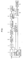
- Fig. 1 is a block diagram showing an example of such a well-known auto focus circuit for a video camera as described above.
- a luminance signal Y contained in a video signal obtained by video recording is applied to a gate circuit 1.
- the gate circuit 1 selects a luminance signal Y corresponding to the sampling area in the center of the screen region.
- a gate control circuit 2 controls an open period of the gate circuit 1 based on the output of a synchronizing separation circuit 3.
- the output of the gate circuit 1 is applied to a high-pass filter 4 for cutting off the signal lower than 100 kHz.
- the output of the filter 4 attains the maximum level in a state in which the video camera is focused.
- the output of the high-pass filter 4 is supplied to an absolute value calculating circuit 5 and then it is integrated for each field in an average value calculating circuit 6.
- the integrated average value output is converted to a digital signal with a cycle of one field in an analog-to-digital (A-D) converting circuit 7.
- the converted output is written in a first memory circuit 8 and then written in a second memory circuit 9 after one field.
- the writing in the first memory circuit 8 and the second memory circuit is controlled by a vertical synchronizing signal V from the synchronizing separation circuit 3.
- the output of the first memory circuit 8 and the output of the second memory circuit 9 are compared in a comparing circuit 10 and the output of comparison is supplied to a focusing motor control circuit 11.
- the focusing motor control circuit 11 rotates in an initialized state, a focusing motor (not shown) in a predetermined direction and the rotation in this direction is maintained as far as the output of the first memory circuit 8 is larger than the output of the second memory circuit 9.
- the focusing motor is controlled to rotate in the opposite direction.
- the focusing motor is controlled so that the average level of the high frequency component contained in the luminance signal is always maximum.
- the average level is considerably changed dependent on the scene to be recorded. More specifically stated, the average output for recording a scene where there is a . considerable change of the luminance in the horizontal direction is ten times as large as the average output for recording a scene where there is little change of the luminance in the horizontal direction. As a result, it is difficult to determine an A-D conversion range for the average output the value of which increases or decreases considerably. Accordingly, if the A-D conversion range is adapted for a high average output, the resolution for a low average output is decreased and the function of response for control is deteriorated. On the contrary, if the A-D conversion range is adapted for a low average level, a saturation of the conversion range with respect to a high average output becomes a problem.
- the A-D conversion range is adapted for a low average value output and an average value output level exceeding the A-D conversion range is detected by a saturation level detecting circuit 12 so that the output of the gate control circuit 2 is controlled.
- scanning lines in the sampling area are decreased by every other line, every two lines, every three lines, etc. so that the average output is not saturated.
- sampling intervals are made less frequent.
- erroneous operation might occur in focusing.
- An object of the present invention is to provide an auto focus circuit for a video camera, capable of focusing with high precision without being influenced by the environmental conditions for video recording, in other words, irrespective of the change in the luminance of an object to be recorded.
- the present invention is an auto focus circuit for a video camera, in which a change in the absolute value output of a high frequency component of a luminance signal in the sampling area for focusing is converted directly to a digital amount and the averaging of the signal is performed by digital processing.
- the averaging of the high frequency component of the luminance signal is digitally performed and as compared with the case of analog processing for averaging the signal, the operation is stable. Consequently, the focusing precision based on the averaged signal is improved.
- an integrating circuit comprising an addition circuit and a latch circuit is used, so that an auto focus circuit of a simple structure having a small storage capacity can be obtained.
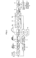
- a luminance signal Y contained in a video signal obtained by recording is supplied to a high-pass filter 4.
- a high frequency component higher than 100 kHz is separated from the luminance signal.
- the separated high frequency component is supplied to an absolute value calculating circuit 5.
- an absolute value of the signal is obtained and the absolute value output is supplied to an envelope detecting circuit 13.
- an envelope of the absolute value output is detected.
- the detected output is supplied to an analog-to-digital (A-D) converting circuit 7.
- the A-D converting circuit 7 converts the received analog envelope detection signal to a digital signal during a predetermined period.
- the luminance signal Y is also supplied to a synchronizing separation circuit 3.
- a horizontal synchronizing signal H and a vertical synchronizing signal V are separated from the luminance signal Y.
- the separated horizontal synchronizing signal H and vertical synchronizing signal V are supplied to a gate control circuit 2.
- the gate control circuit 2 controls a gate circuit 1 so that the gate circuit 1 is opened only in a period corresponding to a predetermined sampling area in the screen region. More specifically, the sampling area is defined by a range from 1/4 to 3/4 of a dimension of the screen region in the horizontal direction and a range from 1/4 to 3/4 of a dimension of the screen region in the vertical direction and the opening of the gate circuit 1 is controlled so that the signal in the sampling area is extracted.
- the sampling area is not limited to the area as defined above and may be an arbitrary region in the screen region. Otherwise, the sampling area may be variable by selecting operation.
- a pulse signal of 5 MHz is supplied from a pulse generating circuit 14.
- the pulse signal of 5 MHz is supplied to the A-D converting circuit 7 in a period in which the gate circuit 1 is opened by the gate control circuit 2, and with the timing of the pulse signal, the analog envelope detecting signal is converted to a digital signal of eight bits for example.
- the pulse signal provided from the gate circuit 1 is supplied as a latch pulse to a latch circuit 12b in an integrating circuit 12 to be described later.
- the pulse signal from the pulse generating circuit 14 may be applied to the gate control circuit 2 for determining the sampling area.
- the integrating circuit 12 comprises an addition circuit 12a and a latch circuit 12b.
- the addition circuit 12a has a closed loop structure in which the digital signal provided from the A-D converting circuit 7 and the digital signal provided from the latch circuit 12b are added and the output of addition is supplied to the latch circuit 12b.
- the latch circuit 12b latches the input signal according to the latch pulse supplied from the above stated gate circuit 1.
- the latch circuit 12b is reset by the vertical synchronizing signal V supplied from the synchronizing separation circuit 3.
- the latch circuit 12b integrates the output of the A-D converting circuit 7 by a field cycle.
- a first memory 8 is connected and to the first memory 8, a second memory 9 is connected. Both of the memories 8 and 9 are controlled by the vertical synchronizing signal V so that writing operation is performed in the memories 8 and 9.
- the memories 8 and 9 provide the signals stored at present as far as new data is not written.
- These first memory 8 and second memory 9 are formed by D-flip-flops for example.
- the resetting of the latch circuit 12b and the writing of the first memory 8 and the second memory 9 are controlled in synchronism with the vertical synchronizing signal V. Accordingly, for each field, the content of the latch circuit 12b is written in the first memory 8 and with a delay of one field, the content is written in the second memory 9.
- a divided vertical synchronizing signal can be used as a control signal. In such a case, for each predetermined period, for example, 1/2 field or 2 fields etc. the content of the latch circuit 12b is written in the first memory 8 and, with a delay of one predetermined period, the content is written in the second memory 9.
- a comparing circuit 10 receiving the output of the first memory 8 and the output of the second memory 9 compares by a field cycle, the digital converted data in one field (this data being supplied from the second memory 9) and the digital converted data in the field coming one field ahead of the above stated field (this data being supplied from the first memory 8) and the output of comparison is supplied to a focusing motor control circuit 11.
- the focusing motor control circuit 11 controls the focusing motor in the same manner as in the prior art so that the most suitable focusing operation is performed.
- processing of the signal after A-D conversion that is, addition, writing and other processing of the digital signal are performed with predetermined timing based on the vertical synchronizing signal V separated from the luminance signal Y.
- processing of the digital signal can be performed using software, in other words, a microcomputer provided with a program for desired operation.
Landscapes
- Engineering & Computer Science (AREA)
- Multimedia (AREA)
- Signal Processing (AREA)
- Theoretical Computer Science (AREA)
- Automatic Focus Adjustment (AREA)
Applications Claiming Priority (2)
| Application Number | Priority Date | Filing Date | Title |
|---|---|---|---|
| JP228308/84 | 1984-10-30 | ||
| JP59228308A JPS61105978A (ja) | 1984-10-30 | 1984-10-30 | オ−トフオ−カス回路 |
Publications (2)
| Publication Number | Publication Date |
|---|---|
| EP0180186A1 true EP0180186A1 (de) | 1986-05-07 |
| EP0180186B1 EP0180186B1 (de) | 1990-01-03 |
Family
ID=16874402
Family Applications (1)
| Application Number | Title | Priority Date | Filing Date |
|---|---|---|---|
| EP85113714A Expired - Lifetime EP0180186B1 (de) | 1984-10-30 | 1985-10-29 | Automatische Fokussierschaltung für Videokameras |
Country Status (5)
| Country | Link |
|---|---|
| US (2) | US4638364A (de) |
| EP (1) | EP0180186B1 (de) |
| JP (1) | JPS61105978A (de) |
| KR (1) | KR920009068B1 (de) |
| DE (1) | DE3575254D1 (de) |
Cited By (6)
| Publication number | Priority date | Publication date | Assignee | Title |
|---|---|---|---|---|
| WO1989006891A1 (en) * | 1988-01-19 | 1989-07-27 | Hughes Aircraft Company | Demand auto focus driven by scene information only |
| EP0249817A3 (en) * | 1986-06-13 | 1989-10-18 | Sanyo Electric Co., Ltd. | Automatic focusing circuit |
| DE3907664A1 (de) * | 1988-03-11 | 1989-10-19 | Canon Kk | Bildaufnahmeeinrichtung |
| EP0341695A3 (en) * | 1988-05-11 | 1990-09-19 | Sanyo Electric Co., Ltd. | Image sensing apparatus having automatic focusing function of automatically matching focus in response to video signal |
| DE3943677C2 (de) * | 1988-03-11 | 1995-11-30 | Canon Kk | Bildaufnahmeeinrichtung |
| US6621521B1 (en) * | 1996-07-26 | 2003-09-16 | Fuji Photo Film Co., Ltd. | Automatic focusing device for film scanner |
Families Citing this family (81)
| Publication number | Priority date | Publication date | Assignee | Title |
|---|---|---|---|---|
| US4762985A (en) * | 1985-04-25 | 1988-08-09 | Canon Kabushiki Kaisha | Auto-focus apparatus applied to image reading apparatus and the like |
| US4841370A (en) * | 1986-11-17 | 1989-06-20 | Sanyo Electric Co., Ltd. | Automatic focusing circuit for automatically matching focus in response to video signal |
| JPH0644806B2 (ja) * | 1987-02-18 | 1994-06-08 | 三洋電機株式会社 | オ−トフオ−カス回路 |
| JPS63276981A (ja) * | 1987-03-04 | 1988-11-15 | Sanyo Electric Co Ltd | オ−トフオ−カス回路 |
| US4922346A (en) * | 1987-06-30 | 1990-05-01 | Sanyo Electric Co., Ltd. | Automatic focusing apparatus having a variable focusing speed and particularly suited for use with interlaced scanning |
| US4833541A (en) * | 1987-09-07 | 1989-05-23 | Sanyo Electric Co., Ltd. | Image sensing apparatus having function of automatically matching focus and exposure in response to video signal |
| US4814889A (en) * | 1987-10-07 | 1989-03-21 | General Electric Company | Automatic focussing system |
| US4975726A (en) * | 1987-11-25 | 1990-12-04 | Matsushita Electric Industrial Co., Ltd. | Automatic focusing apparatus |
| US4843413A (en) * | 1988-03-28 | 1989-06-27 | Eastman Kodak Company | System which uses threshold counts to achieve automatic focus |
| JPH0817452B2 (ja) * | 1989-01-30 | 1996-02-21 | 松下電器産業株式会社 | 自動焦点調節装置 |
| US5249058A (en) * | 1989-08-08 | 1993-09-28 | Sanyo Electric Co., Ltd. | Apparatus for automatically focusing a camera lens |
| JPH03117275A (ja) * | 1989-09-29 | 1991-05-20 | Sanyo Electric Co Ltd | オートフォーカスカメラ |
| DE3938522C2 (de) * | 1989-11-21 | 1998-09-24 | Philips Broadcast Television S | System zum Fokussieren eines Fernsehkamera-Objektivs |
| JP2517415B2 (ja) * | 1989-11-22 | 1996-07-24 | 三洋電機株式会社 | オ―トフォ―カス方法 |
| DE69127112T2 (de) * | 1990-02-28 | 1998-03-05 | Sanyo Electric Co | Automatisches Fokussierungsgerät zur automatischen Fokusanpassung in Abhängigkeit von Videosignalen |
| US5107337A (en) * | 1990-07-24 | 1992-04-21 | Matsushita Electric Industrial Co., Ltd. | Automatic focusing apparatus of video camera |
| KR0130002B1 (ko) * | 1991-07-30 | 1998-04-11 | 강진구 | 비데오 카메라의 오토 포커싱회로 및 방법 |
| US6130716A (en) * | 1991-08-09 | 2000-10-10 | Canon Kabushiki Kaisha | Autofocusing camera device |
| JP3247744B2 (ja) * | 1992-12-25 | 2002-01-21 | キヤノン株式会社 | 撮像装置 |
| KR0143972B1 (ko) * | 1993-03-31 | 1998-07-15 | 김광호 | 비데오 카메라의 자동초점조절방법 및 장치 |
| JP3477742B2 (ja) * | 1993-06-18 | 2003-12-10 | 株式会社ニコン | イメージセンサー |
| JPH09168113A (ja) * | 1995-06-05 | 1997-06-24 | Sony Corp | オートフォーカス装置 |
| WO1996042167A1 (en) * | 1995-06-08 | 1996-12-27 | Sony Corporation | Focus controlling method and video camera device |
| US6812968B1 (en) | 1998-12-31 | 2004-11-02 | Lucent Technologies Inc. | Camera with configurable focus area |
| US7587068B1 (en) | 2004-01-22 | 2009-09-08 | Fotonation Vision Limited | Classification database for consumer digital images |
| US7620218B2 (en) * | 2006-08-11 | 2009-11-17 | Fotonation Ireland Limited | Real-time face tracking with reference images |
| US7844076B2 (en) * | 2003-06-26 | 2010-11-30 | Fotonation Vision Limited | Digital image processing using face detection and skin tone information |
| US7317815B2 (en) * | 2003-06-26 | 2008-01-08 | Fotonation Vision Limited | Digital image processing composition using face detection information |
| US8330831B2 (en) * | 2003-08-05 | 2012-12-11 | DigitalOptics Corporation Europe Limited | Method of gathering visual meta data using a reference image |
| US7792970B2 (en) * | 2005-06-17 | 2010-09-07 | Fotonation Vision Limited | Method for establishing a paired connection between media devices |
| US7680342B2 (en) | 2004-08-16 | 2010-03-16 | Fotonation Vision Limited | Indoor/outdoor classification in digital images |
| US7440593B1 (en) | 2003-06-26 | 2008-10-21 | Fotonation Vision Limited | Method of improving orientation and color balance of digital images using face detection information |
| US8896725B2 (en) * | 2007-06-21 | 2014-11-25 | Fotonation Limited | Image capture device with contemporaneous reference image capture mechanism |
| US8553949B2 (en) | 2004-01-22 | 2013-10-08 | DigitalOptics Corporation Europe Limited | Classification and organization of consumer digital images using workflow, and face detection and recognition |
| US8682097B2 (en) * | 2006-02-14 | 2014-03-25 | DigitalOptics Corporation Europe Limited | Digital image enhancement with reference images |
| US7471846B2 (en) * | 2003-06-26 | 2008-12-30 | Fotonation Vision Limited | Perfecting the effect of flash within an image acquisition devices using face detection |
| US8593542B2 (en) * | 2005-12-27 | 2013-11-26 | DigitalOptics Corporation Europe Limited | Foreground/background separation using reference images |
| US7362368B2 (en) * | 2003-06-26 | 2008-04-22 | Fotonation Vision Limited | Perfecting the optics within a digital image acquisition device using face detection |
| US7574016B2 (en) | 2003-06-26 | 2009-08-11 | Fotonation Vision Limited | Digital image processing using face detection information |
| US9129381B2 (en) * | 2003-06-26 | 2015-09-08 | Fotonation Limited | Modification of post-viewing parameters for digital images using image region or feature information |
| US7269292B2 (en) * | 2003-06-26 | 2007-09-11 | Fotonation Vision Limited | Digital image adjustable compression and resolution using face detection information |
| US8494286B2 (en) | 2008-02-05 | 2013-07-23 | DigitalOptics Corporation Europe Limited | Face detection in mid-shot digital images |
| US8989453B2 (en) * | 2003-06-26 | 2015-03-24 | Fotonation Limited | Digital image processing using face detection information |
| US8948468B2 (en) * | 2003-06-26 | 2015-02-03 | Fotonation Limited | Modification of viewing parameters for digital images using face detection information |
| US8363951B2 (en) | 2007-03-05 | 2013-01-29 | DigitalOptics Corporation Europe Limited | Face recognition training method and apparatus |
| US7616233B2 (en) * | 2003-06-26 | 2009-11-10 | Fotonation Vision Limited | Perfecting of digital image capture parameters within acquisition devices using face detection |
| US8155397B2 (en) * | 2007-09-26 | 2012-04-10 | DigitalOptics Corporation Europe Limited | Face tracking in a camera processor |
| US9692964B2 (en) | 2003-06-26 | 2017-06-27 | Fotonation Limited | Modification of post-viewing parameters for digital images using image region or feature information |
| US7315630B2 (en) | 2003-06-26 | 2008-01-01 | Fotonation Vision Limited | Perfecting of digital image rendering parameters within rendering devices using face detection |
| US7792335B2 (en) | 2006-02-24 | 2010-09-07 | Fotonation Vision Limited | Method and apparatus for selective disqualification of digital images |
| US8498452B2 (en) * | 2003-06-26 | 2013-07-30 | DigitalOptics Corporation Europe Limited | Digital image processing using face detection information |
| US7565030B2 (en) * | 2003-06-26 | 2009-07-21 | Fotonation Vision Limited | Detecting orientation of digital images using face detection information |
| US7564994B1 (en) * | 2004-01-22 | 2009-07-21 | Fotonation Vision Limited | Classification system for consumer digital images using automatic workflow and face detection and recognition |
| US7555148B1 (en) | 2004-01-22 | 2009-06-30 | Fotonation Vision Limited | Classification system for consumer digital images using workflow, face detection, normalization, and face recognition |
| US7551755B1 (en) | 2004-01-22 | 2009-06-23 | Fotonation Vision Limited | Classification and organization of consumer digital images using workflow, and face detection and recognition |
| US7558408B1 (en) | 2004-01-22 | 2009-07-07 | Fotonation Vision Limited | Classification system for consumer digital images using workflow and user interface modules, and face detection and recognition |
| US8320641B2 (en) * | 2004-10-28 | 2012-11-27 | DigitalOptics Corporation Europe Limited | Method and apparatus for red-eye detection using preview or other reference images |
| US7715597B2 (en) | 2004-12-29 | 2010-05-11 | Fotonation Ireland Limited | Method and component for image recognition |
| US7315631B1 (en) | 2006-08-11 | 2008-01-01 | Fotonation Vision Limited | Real-time face tracking in a digital image acquisition device |
| US8503800B2 (en) * | 2007-03-05 | 2013-08-06 | DigitalOptics Corporation Europe Limited | Illumination detection using classifier chains |
| US7804983B2 (en) | 2006-02-24 | 2010-09-28 | Fotonation Vision Limited | Digital image acquisition control and correction method and apparatus |
| US7965875B2 (en) * | 2006-06-12 | 2011-06-21 | Tessera Technologies Ireland Limited | Advances in extending the AAM techniques from grayscale to color images |
| WO2008015586A2 (en) * | 2006-08-02 | 2008-02-07 | Fotonation Vision Limited | Face recognition with combined pca-based datasets |
| US7916897B2 (en) | 2006-08-11 | 2011-03-29 | Tessera Technologies Ireland Limited | Face tracking for controlling imaging parameters |
| US7403643B2 (en) * | 2006-08-11 | 2008-07-22 | Fotonation Vision Limited | Real-time face tracking in a digital image acquisition device |
| US8055067B2 (en) * | 2007-01-18 | 2011-11-08 | DigitalOptics Corporation Europe Limited | Color segmentation |
| DE602008001607D1 (de) | 2007-02-28 | 2010-08-05 | Fotonation Vision Ltd | Trennung der direktionalen beleuchtungsvariabilität in der statistischen gesichtsmodellierung auf basis von texturraumzerlegungen |
| WO2008109622A1 (en) | 2007-03-05 | 2008-09-12 | Fotonation Vision Limited | Face categorization and annotation of a mobile phone contact list |
| EP2188759A1 (de) | 2007-03-05 | 2010-05-26 | Fotonation Vision Limited | Gesichtssuche und detektion in einer digitalbild-beschaffungseinrichtung |
| US7916971B2 (en) * | 2007-05-24 | 2011-03-29 | Tessera Technologies Ireland Limited | Image processing method and apparatus |
| US8750578B2 (en) | 2008-01-29 | 2014-06-10 | DigitalOptics Corporation Europe Limited | Detecting facial expressions in digital images |
| US7855737B2 (en) * | 2008-03-26 | 2010-12-21 | Fotonation Ireland Limited | Method of making a digital camera image of a scene including the camera user |
| CN103475837B (zh) | 2008-05-19 | 2017-06-23 | 日立麦克赛尔株式会社 | 记录再现装置及方法 |
| WO2010012448A2 (en) | 2008-07-30 | 2010-02-04 | Fotonation Ireland Limited | Automatic face and skin beautification using face detection |
| WO2010063463A2 (en) * | 2008-12-05 | 2010-06-10 | Fotonation Ireland Limited | Face recognition using face tracker classifier data |
| US20100295782A1 (en) | 2009-05-21 | 2010-11-25 | Yehuda Binder | System and method for control based on face ore hand gesture detection |
| US8379917B2 (en) * | 2009-10-02 | 2013-02-19 | DigitalOptics Corporation Europe Limited | Face recognition performance using additional image features |
| US8836777B2 (en) | 2011-02-25 | 2014-09-16 | DigitalOptics Corporation Europe Limited | Automatic detection of vertical gaze using an embedded imaging device |
| US20130201316A1 (en) | 2012-01-09 | 2013-08-08 | May Patents Ltd. | System and method for server based control |
| WO2015162605A2 (en) | 2014-04-22 | 2015-10-29 | Snapaid Ltd | System and method for controlling a camera based on processing an image captured by other camera |
| WO2016207875A1 (en) | 2015-06-22 | 2016-12-29 | Photomyne Ltd. | System and method for detecting objects in an image |
Citations (4)
| Publication number | Priority date | Publication date | Assignee | Title |
|---|---|---|---|---|
| DE2241297A1 (de) * | 1972-08-22 | 1974-02-28 | Fuji Photo Film Co Ltd | Verfahren und vorrichtung zum automatischen scharfeinstellen einer fernsehkamera |
| US4301478A (en) * | 1978-11-30 | 1981-11-17 | Canon Kabushiki Kaisha | TV Camera with focus detecting means |
| DE3223879A1 (de) * | 1981-06-26 | 1983-01-13 | Hitachi, Ltd., Tokyo | Verfahren und vorrichtung zur automatischen scharfeinstellung einer videokamera |
| DE3302714A1 (de) * | 1982-01-27 | 1983-08-11 | Hitachi, Ltd., Tokyo | Automatisches fokussierungssystem fuer eine videokamera |
Family Cites Families (10)
| Publication number | Priority date | Publication date | Assignee | Title |
|---|---|---|---|---|
| JPS4958826A (de) * | 1972-10-04 | 1974-06-07 | ||
| JPS51138410A (en) * | 1975-05-26 | 1976-11-30 | Sony Corp | Method of recording and reproducing signal |
| JPS5436709A (en) * | 1977-08-26 | 1979-03-17 | Sony Corp | Position control circuit for rotary magnetic head |
| US4306255A (en) * | 1978-06-22 | 1981-12-15 | Matsushita Electric Industrial Co., Ltd. | Magnetic record/playback system of rotating head type |
| JPS575019A (en) * | 1980-06-13 | 1982-01-11 | Olympus Optical Co Ltd | Focus controller |
| JPS5772111A (en) * | 1980-10-23 | 1982-05-06 | Canon Inc | Camera |
| JPS5772113A (en) * | 1980-10-23 | 1982-05-06 | Canon Inc | Signal processing system |
| JPS57161838A (en) * | 1981-03-31 | 1982-10-05 | Canon Inc | Focus detector of camera |
| JPS5936203A (ja) * | 1982-08-25 | 1984-02-28 | Sony Corp | 画像処理装置 |
| JPS5961807A (ja) * | 1982-09-30 | 1984-04-09 | Canon Inc | 自動焦点制御装置 |
-
1984
- 1984-10-30 JP JP59228308A patent/JPS61105978A/ja active Pending
-
1985
- 1985-10-28 US US06/791,843 patent/US4638364A/en not_active Ceased
- 1985-10-29 KR KR1019850007995A patent/KR920009068B1/ko not_active Expired
- 1985-10-29 DE DE8585113714T patent/DE3575254D1/de not_active Expired - Lifetime
- 1985-10-29 EP EP85113714A patent/EP0180186B1/de not_active Expired - Lifetime
-
1989
- 1989-01-19 US US07/299,189 patent/USRE33682E/en not_active Expired - Lifetime
Patent Citations (4)
| Publication number | Priority date | Publication date | Assignee | Title |
|---|---|---|---|---|
| DE2241297A1 (de) * | 1972-08-22 | 1974-02-28 | Fuji Photo Film Co Ltd | Verfahren und vorrichtung zum automatischen scharfeinstellen einer fernsehkamera |
| US4301478A (en) * | 1978-11-30 | 1981-11-17 | Canon Kabushiki Kaisha | TV Camera with focus detecting means |
| DE3223879A1 (de) * | 1981-06-26 | 1983-01-13 | Hitachi, Ltd., Tokyo | Verfahren und vorrichtung zur automatischen scharfeinstellung einer videokamera |
| DE3302714A1 (de) * | 1982-01-27 | 1983-08-11 | Hitachi, Ltd., Tokyo | Automatisches fokussierungssystem fuer eine videokamera |
Cited By (7)
| Publication number | Priority date | Publication date | Assignee | Title |
|---|---|---|---|---|
| EP0249817A3 (en) * | 1986-06-13 | 1989-10-18 | Sanyo Electric Co., Ltd. | Automatic focusing circuit |
| WO1989006891A1 (en) * | 1988-01-19 | 1989-07-27 | Hughes Aircraft Company | Demand auto focus driven by scene information only |
| DE3907664A1 (de) * | 1988-03-11 | 1989-10-19 | Canon Kk | Bildaufnahmeeinrichtung |
| DE3943677C2 (de) * | 1988-03-11 | 1995-11-30 | Canon Kk | Bildaufnahmeeinrichtung |
| EP0341695A3 (en) * | 1988-05-11 | 1990-09-19 | Sanyo Electric Co., Ltd. | Image sensing apparatus having automatic focusing function of automatically matching focus in response to video signal |
| US6621521B1 (en) * | 1996-07-26 | 2003-09-16 | Fuji Photo Film Co., Ltd. | Automatic focusing device for film scanner |
| US6989864B2 (en) * | 1996-07-26 | 2006-01-24 | Fuji Photo Film Co., Ltd. | Automatic focusing device for film scanner |
Also Published As
| Publication number | Publication date |
|---|---|
| US4638364A (en) | 1987-01-20 |
| DE3575254D1 (de) | 1990-02-08 |
| KR860003729A (ko) | 1986-05-28 |
| USRE33682E (en) | 1991-09-03 |
| JPS61105978A (ja) | 1986-05-24 |
| EP0180186B1 (de) | 1990-01-03 |
| KR920009068B1 (ko) | 1992-10-13 |
Similar Documents
| Publication | Publication Date | Title |
|---|---|---|
| US4638364A (en) | Auto focus circuit for video camera | |
| US4967279A (en) | Automatic focusing circuit | |
| US5341218A (en) | Video signals clamping circuit for maintaining DC level of video signals | |
| EP0287333A3 (de) | Zoomvorrichtung für Fernsehbild | |
| US5905848A (en) | Image pickup apparatus with vibration compensation | |
| US4853789A (en) | Automatic focusing circuit using a two period detection interval to compensate for motion occurring within a field of view | |
| US4222077A (en) | Analog-digital conversion method, and a picture reproduction method using the same | |
| US4364087A (en) | Movement detector for television signals | |
| US5946033A (en) | Method and apparatus for multiple read-out speeds for a CTD | |
| US4833541A (en) | Image sensing apparatus having function of automatically matching focus and exposure in response to video signal | |
| EP0553850A1 (de) | Automatische Fokussierungsschaltung für automatische Fokusanpassung in Abhängigkeit von Videosignalen | |
| US4445092A (en) | Periodic pulse forming circuit | |
| US4109211A (en) | Variable thresholding circuit for converting an analog signal to a binary signal | |
| US5485222A (en) | Method of determining the noise component in a video signal | |
| US4667237A (en) | Image signal processing device | |
| KR100254028B1 (ko) | 자동 화이트 밸런스 제어 장치 | |
| US7103425B1 (en) | Method of regulating a target system using a frequency comparison of feedback and reference pulse trains | |
| US5432552A (en) | Automatic focusing apparatus including improved digital high-pass filter | |
| US4325082A (en) | Digital measurement system for automatically focusing a television camera | |
| US5568201A (en) | Clock signal generating apparatus | |
| JPH11252580A (ja) | ビデオデコーダ及びこれに用いるカラー位相ロックループ | |
| JP2643247B2 (ja) | デジタル同期検出装置 | |
| JPH0312837B2 (de) | ||
| JPS6342913B2 (de) | ||
| JPH0345081A (ja) | ドリフト補正回路 |
Legal Events
| Date | Code | Title | Description |
|---|---|---|---|
| PUAI | Public reference made under article 153(3) epc to a published international application that has entered the european phase |
Free format text: ORIGINAL CODE: 0009012 |
|
| AK | Designated contracting states |
Kind code of ref document: A1 Designated state(s): DE FR GB |
|
| 17P | Request for examination filed |
Effective date: 19860321 |
|
| 17Q | First examination report despatched |
Effective date: 19870330 |
|
| GRAA | (expected) grant |
Free format text: ORIGINAL CODE: 0009210 |
|
| AK | Designated contracting states |
Kind code of ref document: B1 Designated state(s): DE FR GB |
|
| REF | Corresponds to: |
Ref document number: 3575254 Country of ref document: DE Date of ref document: 19900208 |
|
| ET | Fr: translation filed | ||
| PLBE | No opposition filed within time limit |
Free format text: ORIGINAL CODE: 0009261 |
|
| STAA | Information on the status of an ep patent application or granted ep patent |
Free format text: STATUS: NO OPPOSITION FILED WITHIN TIME LIMIT |
|
| 26N | No opposition filed | ||
| REG | Reference to a national code |
Ref country code: GB Ref legal event code: IF02 |
|
| PGFP | Annual fee paid to national office [announced via postgrant information from national office to epo] |
Ref country code: FR Payment date: 20041008 Year of fee payment: 20 |
|
| PGFP | Annual fee paid to national office [announced via postgrant information from national office to epo] |
Ref country code: DE Payment date: 20041021 Year of fee payment: 20 |
|
| PGFP | Annual fee paid to national office [announced via postgrant information from national office to epo] |
Ref country code: GB Payment date: 20041027 Year of fee payment: 20 |
|
| PG25 | Lapsed in a contracting state [announced via postgrant information from national office to epo] |
Ref country code: GB Free format text: LAPSE BECAUSE OF EXPIRATION OF PROTECTION Effective date: 20051028 |
|
| REG | Reference to a national code |
Ref country code: GB Ref legal event code: PE20 |