EP0180206A2 - Bloc de barres omnibus - Google Patents
Bloc de barres omnibus Download PDFInfo
- Publication number
- EP0180206A2 EP0180206A2 EP85113771A EP85113771A EP0180206A2 EP 0180206 A2 EP0180206 A2 EP 0180206A2 EP 85113771 A EP85113771 A EP 85113771A EP 85113771 A EP85113771 A EP 85113771A EP 0180206 A2 EP0180206 A2 EP 0180206A2
- Authority
- EP
- European Patent Office
- Prior art keywords
- busbar
- busbar according
- busbars
- side walls
- longitudinal side
- Prior art date
- Legal status (The legal status is an assumption and is not a legal conclusion. Google has not performed a legal analysis and makes no representation as to the accuracy of the status listed.)
- Granted
Links
Images
Classifications
-
- H—ELECTRICITY
- H02—GENERATION; CONVERSION OR DISTRIBUTION OF ELECTRIC POWER
- H02B—BOARDS, SUBSTATIONS OR SWITCHING ARRANGEMENTS FOR THE SUPPLY OR DISTRIBUTION OF ELECTRIC POWER
- H02B1/00—Frameworks, boards, panels, desks, casings; Details of substations or switching arrangements
- H02B1/20—Bus-bar or other wiring layouts, e.g. in cubicles, in switchyards
- H02B1/205—Bus-bar or other wiring layouts, e.g. in cubicles, in switchyards for connecting electrical apparatus mounted side by side on a rail
Definitions
- the invention relates to a packaged busbar with a plastic housing, which contains a base part, two parallel longitudinal side walls and internal dividing walls running parallel to the longitudinal side walls, through which chambers are formed, in each of which busbars are arranged insulated from one another.
- busbars are already known (DE-OS 25 54 732).
- the busbars are made from an extruded plastic profile that is cut to the desired length of the busbars. An adaptation to the required length of busbar is therefore possible in a simple manner.
- In the bottom part of the busbar there are grooves which are open towards the bottom and towards the side and which have a cross-shaped cross section. Threaded strips can be inserted into the grooves, into which screws are inserted to fasten the busbars to support elements.
- a connecting rail block with busbars inserted into a multi-chamber insulating profile is also known.
- Two short, bevelled strips protrude from the bottom of the connecting rail block and are intended to be snapped onto a mounting rail.
- Such a mounting rail can be mounted parallel to an installation device rail on a base plate (DE-OS 30 24 844).
- busbars are arranged parallel to one another in a metal housing with the interposition of insulating sleeves.
- the metal housing merges into two profiled rails on two opposite sides, in the interior of which a carrier containing the same outline is inserted (US Pat. No. 3,444,311).
- the invention has for its object to develop a busbar of the type described in such a way that it can be easily and quickly attached as a self-supporting unit on flat, spaced apart at the same level support surfaces.
- the intermediate plates can be connected to the plastic housing by hand at any point in the longitudinal direction of the housing.
- the elastic extension sections spring laterally outwards when the intermediate plate is inserted, so that the intermediate plates can be connected to the plastic housing by snapping them into place. A longitudinal displacement of the intermediate plate inserted into the plastic housing to the intended installation location is therefore no longer necessary.
- the packaged busbar is then attached to the brackets by snapping the intermediate plates.
- the assembly process e.g. B. in control cabinets, this makes it much easier.
- the intermediate plates can also be connected to the plastic housing before being attached to a carrier. They are held non-positively at the installation point by the resilient projection and each form a unit that can be handled by itself with the plastic housing.
- each intermediate plate has claw-like curved longitudinal edge regions, the end faces of which bear against the inner sides of the angled parts of the extension sections, with projections protruding from the angled ends into the interior of the claw-like longitudinal edge sections.
- the ends of the extension sections are pressed onto the claw-like curved longitudinal edge sections of the fastening plates.
- the extension sections spread apart until the angled ends have reached the height of the end faces of the intermediate plates.
- the extension sections then spring back into their position in alignment with the other parts of the longitudinal side walls, the claw-like longitudinal edge sections coming into their position defined by the projections and being held therein.
- the resilient projection protruding into the space between the extension sections is designed as a tongue extending obliquely from the bottom part of the chambers.
- the tongue has a sufficient length so that there is a sufficient path for the deflection of the tongue when the intermediate plate is inserted.
- Another advantageous possibility is to provide the angled ends with locking projections running in the longitudinal direction, which are arranged on both sides of the inner corners, the ends of the intermediate plates which can be connected to the carrier being inserted between the locking projections.
- the intermediate plate is expediently provided with at least one threaded hole arranged in the middle.
- the intermediate plate can optionally be screwed onto a support from two sides before a busbar is attached.
- the transverse projection preferably merges on a longitudinal side wall into a wall section which delimits the outer chamber for the busbars and which runs parallel to the bottom section at a distance from the extension section.
- one extension section has a greater height than the other extension section. An improved spring action can thus be achieved.
- the higher extension section can take over the main part of the resilient deflection when mounting the busbar. It is possible to make the second extension section very short. The space required by the extension sections is therefore low.
- one of the partitions before the transition to the base part is provided with a widened wall section in which there is an elongated recess for self-tapping screws with which covers can be screwed onto the end faces of the plastic housing.
- a particularly advantageous embodiment is designed such that the end faces can be covered with lids which fork in the space below the bottom part of the chambers in two end plates, each of which can be inserted into a slot in the claw-like bent longitudinal edge sections.
- the covers prevent undesired relative movement in the axial direction between the packaged busbar and the intermediate plates. It is expedient if the busbar is attached at one end to an intermediate plate in the manner described above, while an intermediate plate set back against the second cover is connected to the busbar at at least one second point. Such attachment allows longitudinal dimensions of the packaged busbar, for. B. due to rising temperatures.
- the busbars preferably have projecting pins and / or knives which are arranged at a distance from one another and do not protrude beyond the longitudinal side walls and end caps. Therefore, touch-proof cable connections can be made with plug-on elements.
- the busbar is also suitable for higher voltages, e.g. B. Mains voltage.
- B. Mains voltage In order to reduce the dimensions of the busbars, it is expedient to produce the busbars from copper, which consists of a copper strip folded at least once by 180 ° and is sufficiently hard to permit connectors using Faston technology.
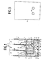
- a packaged busbar 1 has a plastic housing 2, which contains two longitudinal side walls 3, 4, a bottom part 5 and inside two partition walls 6, 7, which run parallel to the longitudinal side walls 3, 4.
- the longitudinal side walls 3, 4 and the partitions 6, 7 form chambers 8, into which busbars 9 are inserted, which are preferably made of copper.
- the busbars 9 are insulated from one another by the partitions 6, 7.
- Extension sections 10, 11 extend from the longitudinal side walls 3, 4 and protrude a little beyond the base part 5.
- the extension sections 10, 11 have ends 12, 13 bent at right angles on.
- On both sides of the inner corners 14, 15 of the angled ends 12, 13, 4 locking projections 16, 17 and 18, 19 extend in the longitudinal direction of the housing.
- the locking projections 16, 17 and 18, 19 are located at a distance from the corners 14, 15.
- An intermediate plate 20 has two claw-like bent-over Lijn "welt portions 21 which extend in the longitudinal direction of the housing. 2
- the dimensions of the intermediate plate 20 are adapted to the space between the extension portions 10,. 11
- the end faces 22 of the longitudinal edges of portions 21 are located in the same Height in a plane which roughly corresponds to the plane passing through the surface of the intermediate plate 20.
- the claw-like bent longitudinal edge portions 21 are each pressed between the locking projections 16, 17 and 18, 19.
- the end faces 22 of the longitudinal edge sections 21 lie against the inner, unspecified surfaces of the ends 12, 13.
- the housing 2 consists of an elastic material.
- the gap between the locking projections 16, 17 and 18, 19 is chosen so large that the longitudinal edge portions 21 can only be inserted into the gaps by a certain elastic deformation of the locking projections 16, 17 and 18, 19.
- the elastic deformation exerts holding forces on the longitudinal edge sections 18, 19.
- a threaded bore 23 is provided, into which a screw 24 is inserted, with which the intermediate plate 20 can be screwed onto a carrier 25.
- Protrusions 26, 27 protrude from the longitudinal side walls 3, 4 into the interior of the housing 2.
- the protrusions 26, 27 can be at the same height.
- At least one partition 6 or 7 has projections 28, 29 which protrude into the chambers 8.
- the projections 28, 29, which are at the same height as the projection 26, start from mutually opposite sides of the partition walls 6 and 7, respectively.
- the projections 26, 28 and 29 have unspecified surfaces facing the bottom part 5, the distance from the bottom part 5 of which corresponds to the height of the busbar 9.
- the busbars 9 are inserted into the spaces between the base part 5 and the projections 26, 28 and 29. Between the opposite sides of the front jumps 26 and 28 or 28 and 29 or 29 and 27 there is a gap which is smaller than the thickness of the busbar 9.
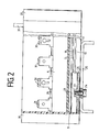
- the pins 30 and knives 31 end below the longitudinal side walls 3, 4 and the dividing walls 6, 7. If necessary, lines are attached to the pins 30 and the knives 31, which are spaced apart from one another in the longitudinal direction of the busbars 9, with the aid of plug-in shoes.
- the plug connections are located in a touch-safe manner below the upper edges of the longitudinal side walls 3, 4 and the partition walls 7, 8.
- the projection 27 merges at a short distance from the extension section 11 into a wall section 32 running parallel to this, which extends to the bottom part 5.
- the extension section 11 is longer than the extension section 10, which ends at the bottom part 5.
- the distance between the extension sections 10, 11 must be increased. This is possible due to the elastic properties of the extension sections 10, 11. Due to the greater length of the extension section 11, this can be deflected to the side more than the extension section 10. It is possible to let the extension section 10 protrude only slightly beyond the base part 5, since the extension section 10 has no or only a small deflection when mounting the housing 2 must run on the intermediate plate 20. In this way, the housing can be designed to save space. A further saving of space results from the use of copper as busbar material, since the high conductivity means that large currents can be transported even with small dimensions.
- the partition 7 has a widened wall section 33 before the transition into the base part 5, in which there is a recess 34 for self-tapping screws.
- the recess 34 which runs from the front to the front of the housing 2, has a slot-shaped opening in the base part 5.
- Lids 35 are screwed to the end faces of the housing 2 by means of countersunk screws (not shown). Each cover 35 contains two bores which are arranged next to one another at the same height.
- Busbars can also be arranged in series in a housing 2. Since the busbars are then provided for different potentials, they are insulated from one another by partition walls 37.
- the carrier 25 can preferably be arranged in a cabinet for electrical or electronic devices.
- FIG. 1 shows a packaged busbar 1 with three busbars 9, which are fed, for example, from the three phases of the three-phase network. It is possible to use the frame of a control cabinet as the support 25, the frame profiles of which are designed for the attachment of inserts, plug-in units, devices and also power supply devices for these devices.
- This type of control cabinets contain hollow profiles with rows of holes, with which z. B. the intermediate plates 20 are connected to which the packaged busbars are plugged.
- Such a cabinet has been proposed in patent application P 34 04 349.7.
- the packaged busbar 1 is pressed against the longitudinal edge sections by hand with the extension sections 10, 11 for mounting on a fastening plate 20.
- the extension section 11 springs to the side so that the ends 12, 13 can slide over the longitudinal edge sections 21.
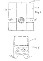
- the embodiment of a plastic housing 2 shown in FIG. 4 does not have the locking projections 16, 18.
- the same elements are provided with the same reference symbols.
- the angled, each other facing ends 12, 13 each contain a pair of parallel support projections 37, 38 with which the housing 2 rests on the carrier 25.
- the support projections 37, 38 project downwards.
- the projections 17, 19 each project into the space between the extension sections 10, 11.
- a resilient tongue 39 extends from the base part 5 as a projection.
- the base of the resilient tongue 39 is located at the point at which the opening running to the recess 34 begins.
- the tongue 39 protrudes obliquely to the level of the base part 5 into the space between the extension sections 10, 11. In a relaxed position, the end 40 of the tongue is at the level of the angled ends 12, 13.
- a particularly firm connection between the carrier 25 and the housing 2 can be achieved if the screw 24 is tightened to such an extent that the ends 12, 13 are firmly clamped between the end faces 22 and the carrier 25.
- the elastic projections 37, 38 can deform somewhat, whereby resilient clamping is achieved.
- connection between the housing 2 and the intermediate plate 20 can take place before or after the intermediate plate 20 is screwed onto the carrier 25. If the housing 2 is to be connected to an intermediate plate 20 already fastened to a carrier 25, the intermediate plate 20 must be loosely attached to the carrier 25 above the screw 24.
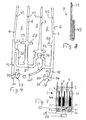
- FIG. 5 shows an intermediate plate 20, in which the longitudinal edge sections 21 are interrupted on both sides at the level of the threaded bore 23 by slots 46.
- the slots 46 serve to receive end plates 41 into which the exemplary embodiment of a cover shown in FIG. 6 bifurcates.
- the end plates 41 start below the bottom part 5, i.e. H. the busbars 9 are completely covered by the covers 35.
- the intermediate plate 20 When the end plates 41 protrude into the slots 46, the intermediate plate 20 is fixed in position in the longitudinal direction of the housing 2. This type of fixation is expediently carried out only at one end in the case of packaged conductor rails. Near the other end, the intermediate plate 21 is shifted inwards a little against the end of the busbar.
- This type of attachment allows changes in length of the plastic housing 2. Due to fluctuations in the ambient temperature and changing current loads on the busbars that cause different temperatures in the busbars, the plastic housings are exposed to fluctuating temperatures over a wide range. Here, changes in length occur which do not lead to undesirable tensions or stresses on the plastic housing 2 in the above-described fastening by means of intermediate plates which form a fixed bearing and a floating bearing. If packaged busbars of very great length are required, a plurality of floating bearings can also be arranged along the busbar 1 by means of intermediate plates 20.
- the dividing walls 6, 7 and the longitudinal side walls 3, 4 each have predetermined breaking points 42 near their upper ends in order to shorten the heights.
- the height of the longitudinal side walls 3, 4 and the dividing walls 6, 7 depends on the level of the voltage of the busbars 9. With smaller nominal voltages and thus smaller prescribed air and creepage distances between the busbars 9, the wall sections lying above the predetermined breaking points 42 can be broken off in order to save space for other arrangements in the switchgear or equipment cabinet.
- FIG. 7 shows a cross section of a packaged busbar covered on one end face by a cover 35.
- the cover 35 contains projections 43, which each protrude into the chambers 8 and bear against wall sections of the longitudinal side walls 3, 4 and the partition walls 6, 7.
- the cover 35 is thus fixed in its position, although it is only attached to the housing 2 with a screw. If necessary, further projections 44 can be arranged on the cover 35 at a different height.
- the busbars 9 consist of a copper strip bent several times by 180 °.
- the material is preferably semi-hard and hard copper. Such hardness is necessary to connect connecting elements, for. B. flat tabs to use in Faston technology.
- a favorable embodiment consists of a 0.8 mm thick copper band, which has two folds running in the longitudinal direction of the rail by 180 °.
- the copper material is of type Cu 57 F 25 or Cu 57 F 37 and has a microhardness of 70 to 120 according to DIN 40 500.
- the use of copper allows a high current load due to its high conductivity with a small cross-section. Due to the small cross-section, the package busbar has smaller dimensions, the plastic housing 2 of which is preferably produced as an extruded part.
- Silver alloy copper of the type CuAg 0.1 is also suitable as the material for the busbars 9. With a width of 2.7 mm and a height of the base body of 10 to 11 mm, the current carrying capacity of material of the type described above and double folding is approximately 100 A.
- the pins 30 and knives 31 are made by punching the copper tape.
- the busbars 9 contain a base body 45, the cross section of which is enlarged by the folds to the area required for the desired current load. The low effort to manufacture the busbars 9 is of particular importance.
- the thickness of the copper strip for the busbars can range from 0.8 mm to 1.1 mm.
- the busbar 9 described above can advantageously also be used in housings which have a different structure than the plastic housing explained above, if economically producible busbars with flat plug elements are required. It is also possible to hold the busbars 9 at two or more locations by means of insulating supports and to leave them blank. Such an arrangement is appropriate if the voltages are low or if the busbars are mounted in a housing so that they are safe to touch.
Landscapes
- Engineering & Computer Science (AREA)
- Power Engineering (AREA)
- Installation Of Bus-Bars (AREA)
- Details Of Indoor Wiring (AREA)
- Connector Housings Or Holding Contact Members (AREA)
- Coupling Device And Connection With Printed Circuit (AREA)
- Connection Or Junction Boxes (AREA)
- Packaging Of Annular Or Rod-Shaped Articles, Wearing Apparel, Cassettes, Or The Like (AREA)
Priority Applications (1)
| Application Number | Priority Date | Filing Date | Title |
|---|---|---|---|
| AT85113771T ATE83091T1 (de) | 1984-11-02 | 1985-10-29 | Paketierte sammelschiene. |
Applications Claiming Priority (2)
| Application Number | Priority Date | Filing Date | Title |
|---|---|---|---|
| DE19843440008 DE3440008A1 (de) | 1984-11-02 | 1984-11-02 | Paketierte sammelschiene |
| DE3440008 | 1984-11-02 |
Publications (3)
| Publication Number | Publication Date |
|---|---|
| EP0180206A2 true EP0180206A2 (fr) | 1986-05-07 |
| EP0180206A3 EP0180206A3 (en) | 1988-09-14 |
| EP0180206B1 EP0180206B1 (fr) | 1992-12-02 |
Family
ID=6249283
Family Applications (1)
| Application Number | Title | Priority Date | Filing Date |
|---|---|---|---|
| EP85113771A Expired - Lifetime EP0180206B1 (fr) | 1984-11-02 | 1985-10-29 | Bloc de barres omnibus |
Country Status (3)
| Country | Link |
|---|---|
| EP (1) | EP0180206B1 (fr) |
| AT (1) | ATE83091T1 (fr) |
| DE (2) | DE3440008A1 (fr) |
Cited By (5)
| Publication number | Priority date | Publication date | Assignee | Title |
|---|---|---|---|---|
| DE3827683A1 (de) * | 1988-08-16 | 1990-02-22 | Licentia Gmbh | Paketierte sammelschiene |
| US5088453A (en) * | 1990-06-29 | 1992-02-18 | Mercedes-Benz Ag | Delivery valve unit on a compensating tank |
| CN100345352C (zh) * | 2004-09-29 | 2007-10-24 | 清华大学 | 一种故障电流限制器 |
| CN100397736C (zh) * | 2004-12-17 | 2008-06-25 | 常州太平洋电力设备(集团)有限公司 | 充气柜母线室 |
| CN107739097A (zh) * | 2017-11-24 | 2018-02-27 | 苏州科技大学 | 一种脱碳除磷的污水处理系统 |
Family Cites Families (8)
| Publication number | Priority date | Publication date | Assignee | Title |
|---|---|---|---|---|
| US3444311A (en) * | 1966-06-24 | 1969-05-13 | Westinghouse Electric Corp | Bus duct |
| DE2554732A1 (de) * | 1975-12-05 | 1977-06-08 | Licentia Gmbh | Paketierte sammelschiene fuer elektronische baugruppen |
| DE2616525C2 (de) * | 1976-04-14 | 1984-06-14 | Brown, Boveri & Cie Ag, 6800 Mannheim | Elektrische Installationsverteilung |
| DK150048C (da) * | 1978-07-03 | 1987-05-11 | Knudsen Nordisk Elect | Formstofisolering til stroemfoerende, parallelle skinner |
| DE7909435U1 (de) * | 1978-11-07 | 1979-07-05 | Neubacher, Karl, Salzburg (Oesterreich) | Paketverschienung |
| DE2912944A1 (de) * | 1979-03-31 | 1980-10-16 | Bbc Brown Boveri & Cie | Sammelschienenblock |
| NL7908471A (nl) * | 1979-11-20 | 1981-06-16 | Hiemstra Evolux Bv | Bevestigings- of ophangsamenstel voor een kabelkoker. |
| DE3024844A1 (de) * | 1980-07-01 | 1982-02-04 | Brown, Boveri & Cie Ag, 6800 Mannheim | Verbindungsschienenblock |
-
1984
- 1984-11-02 DE DE19843440008 patent/DE3440008A1/de not_active Ceased
-
1985
- 1985-10-29 DE DE8585113771T patent/DE3586871D1/de not_active Expired - Fee Related
- 1985-10-29 AT AT85113771T patent/ATE83091T1/de active
- 1985-10-29 EP EP85113771A patent/EP0180206B1/fr not_active Expired - Lifetime
Cited By (6)
| Publication number | Priority date | Publication date | Assignee | Title |
|---|---|---|---|---|
| DE3827683A1 (de) * | 1988-08-16 | 1990-02-22 | Licentia Gmbh | Paketierte sammelschiene |
| EP0355448A1 (fr) * | 1988-08-16 | 1990-02-28 | Licentia Patent-Verwaltungs-GmbH | Bloc de barres omnibus |
| US5088453A (en) * | 1990-06-29 | 1992-02-18 | Mercedes-Benz Ag | Delivery valve unit on a compensating tank |
| CN100345352C (zh) * | 2004-09-29 | 2007-10-24 | 清华大学 | 一种故障电流限制器 |
| CN100397736C (zh) * | 2004-12-17 | 2008-06-25 | 常州太平洋电力设备(集团)有限公司 | 充气柜母线室 |
| CN107739097A (zh) * | 2017-11-24 | 2018-02-27 | 苏州科技大学 | 一种脱碳除磷的污水处理系统 |
Also Published As
| Publication number | Publication date |
|---|---|
| DE3586871D1 (de) | 1993-01-14 |
| EP0180206A3 (en) | 1988-09-14 |
| ATE83091T1 (de) | 1992-12-15 |
| DE3440008A1 (de) | 1986-07-03 |
| EP0180206B1 (fr) | 1992-12-02 |
Similar Documents
| Publication | Publication Date | Title |
|---|---|---|
| DE69511156T2 (de) | Sammelschienenanordnung, insbesondere für eine Energieverteilungsschrank | |
| DE102010051899B4 (de) | Elektrisches Klemmenbauelement | |
| DE19544835C1 (de) | Bauteil für HF-dichte Behältnisse | |
| EP0872000B1 (fr) | Jeu de barres omnibus pour installation de commutation basse tension | |
| EP1994614B1 (fr) | Construction a cadre pour une armoire electrique, armoire electrique et kit pour l'armoire electrique | |
| DE3441416C2 (de) | Elektrische Steckverbindung | |
| EP0086316B1 (fr) | Dispositif à contact enfichable pour la réalisation d'une connexion électrique entre deux barres omnibus | |
| EP0466043B1 (fr) | Installation de distribution comprenant au moins deux rangées d'appareils électriques de type étroit | |
| EP0180206B1 (fr) | Bloc de barres omnibus | |
| EP0264686A1 (fr) | Barres de maintien connectables à des barres profilées d'un support de plaquettes de composants | |
| DE19751705C2 (de) | Verrasteter Einbaublock | |
| EP0125489B1 (fr) | Assemblage de contact pour connecter des conducteurs de câble avec des barres omnibus | |
| DE1765854B2 (de) | AnschluBvorrichtung für eine am Rand mit elektrischen Leiterbahnen versehene Platine | |
| DE3829421C2 (fr) | ||
| DE19748555C1 (de) | Schaltschrank | |
| DE3827683C2 (fr) | ||
| DE3201169A1 (de) | Vorrichtung zum festklemmen elektrischer leiter insbesondere von draehten | |
| DE8700153U1 (de) | Sammelschienenblock | |
| DE1765056A1 (de) | Anschlussschiene fuer die Versorgung von Verbrauchern mit elektrischem Strom | |
| DE2739242B1 (de) | Hochleistungsstromrichter | |
| EP0217160B1 (fr) | Plaque porteuse à profil pour constructions électriques intérieures aux composants calorifiques | |
| DE29805626U1 (de) | Einschub für einen elektrischen Schaltschrank, insbesondere einen Niederspannungsschaltschrank | |
| EP0311952A2 (fr) | Support de barres omnibus | |
| DE1864359U (de) | Mehrpoliger steckschuh fuer kontakt-federleisten, insbesondere bei gedruckten schaltungen. | |
| DE3328305A1 (de) | Installationsgeraet, insbesondere leitungsschutzschalter |
Legal Events
| Date | Code | Title | Description |
|---|---|---|---|
| PUAI | Public reference made under article 153(3) epc to a published international application that has entered the european phase |
Free format text: ORIGINAL CODE: 0009012 |
|
| AK | Designated contracting states |
Kind code of ref document: A2 Designated state(s): AT BE DE NL |
|
| PUAL | Search report despatched |
Free format text: ORIGINAL CODE: 0009013 |
|
| AK | Designated contracting states |
Kind code of ref document: A3 Designated state(s): AT BE DE NL |
|
| 17P | Request for examination filed |
Effective date: 19881201 |
|
| 17Q | First examination report despatched |
Effective date: 19901127 |
|
| GRAA | (expected) grant |
Free format text: ORIGINAL CODE: 0009210 |
|
| AK | Designated contracting states |
Kind code of ref document: B1 Designated state(s): AT BE DE NL |
|
| REF | Corresponds to: |
Ref document number: 83091 Country of ref document: AT Date of ref document: 19921215 Kind code of ref document: T |
|
| REF | Corresponds to: |
Ref document number: 3586871 Country of ref document: DE Date of ref document: 19930114 |
|
| PLBE | No opposition filed within time limit |
Free format text: ORIGINAL CODE: 0009261 |
|
| STAA | Information on the status of an ep patent application or granted ep patent |
Free format text: STATUS: NO OPPOSITION FILED WITHIN TIME LIMIT |
|
| 26N | No opposition filed | ||
| PGFP | Annual fee paid to national office [announced via postgrant information from national office to epo] |
Ref country code: BE Payment date: 19941011 Year of fee payment: 10 Ref country code: AT Payment date: 19941011 Year of fee payment: 10 |
|
| PGFP | Annual fee paid to national office [announced via postgrant information from national office to epo] |
Ref country code: NL Payment date: 19941031 Year of fee payment: 10 |
|
| PGFP | Annual fee paid to national office [announced via postgrant information from national office to epo] |
Ref country code: DE Payment date: 19951025 Year of fee payment: 11 |
|
| PG25 | Lapsed in a contracting state [announced via postgrant information from national office to epo] |
Ref country code: AT Effective date: 19951029 |
|
| PG25 | Lapsed in a contracting state [announced via postgrant information from national office to epo] |
Ref country code: BE Effective date: 19951031 |
|
| BERE | Be: lapsed |
Owner name: LICENTIA PATENT-VERWALTUNGS-G.M.B.H. Effective date: 19951031 |
|
| PG25 | Lapsed in a contracting state [announced via postgrant information from national office to epo] |
Ref country code: NL Effective date: 19960501 |
|
| NLV4 | Nl: lapsed or anulled due to non-payment of the annual fee |
Effective date: 19960501 |
|
| PG25 | Lapsed in a contracting state [announced via postgrant information from national office to epo] |
Ref country code: DE Effective date: 19970701 |