EP0180231A2 - Circuit statique de compensation d'énergie réactive - Google Patents
Circuit statique de compensation d'énergie réactive Download PDFInfo
- Publication number
- EP0180231A2 EP0180231A2 EP85113883A EP85113883A EP0180231A2 EP 0180231 A2 EP0180231 A2 EP 0180231A2 EP 85113883 A EP85113883 A EP 85113883A EP 85113883 A EP85113883 A EP 85113883A EP 0180231 A2 EP0180231 A2 EP 0180231A2
- Authority
- EP
- European Patent Office
- Prior art keywords
- reactor
- capacitor
- var compensator
- static var
- static
- Prior art date
- Legal status (The legal status is an assumption and is not a legal conclusion. Google has not performed a legal analysis and makes no representation as to the accuracy of the status listed.)
- Granted
Links
Images


Classifications
-
- H—ELECTRICITY
- H02—GENERATION; CONVERSION OR DISTRIBUTION OF ELECTRIC POWER
- H02J—ELECTRIC POWER NETWORKS; CIRCUIT ARRANGEMENTS OR SYSTEMS FOR SUPPLYING OR DISTRIBUTING ELECTRIC POWER; SYSTEMS FOR STORING ELECTRIC ENERGY
- H02J3/00—Circuit arrangements for AC mains or AC distribution networks
- H02J3/18—Arrangements for adjusting, eliminating or compensating reactive power in networks
- H02J3/1821—Arrangements for adjusting, eliminating or compensating reactive power in networks using shunt compensators
- H02J3/1835—Arrangements for adjusting, eliminating or compensating reactive power in networks using shunt compensators with stepless control
- H02J3/1864—Arrangements for adjusting, eliminating or compensating reactive power in networks using shunt compensators with stepless control using reactive elements connected in series with semiconductor switches, e.g. static VAR compensators [SVC], thyristor-controlled reactors [TCR] or thyristor-switched capacitors [TSC]
-
- Y—GENERAL TAGGING OF NEW TECHNOLOGICAL DEVELOPMENTS; GENERAL TAGGING OF CROSS-SECTIONAL TECHNOLOGIES SPANNING OVER SEVERAL SECTIONS OF THE IPC; TECHNICAL SUBJECTS COVERED BY FORMER USPC CROSS-REFERENCE ART COLLECTIONS [XRACs] AND DIGESTS
- Y02—TECHNOLOGIES OR APPLICATIONS FOR MITIGATION OR ADAPTATION AGAINST CLIMATE CHANGE
- Y02E—REDUCTION OF GREENHOUSE GAS [GHG] EMISSIONS, RELATED TO ENERGY GENERATION, TRANSMISSION OR DISTRIBUTION
- Y02E40/00—Technologies for an efficient electrical power generation, transmission or distribution
- Y02E40/10—Flexible AC transmission systems [FACTS]
Definitions
- This invention relates to a static var (voltampere reactive) compensator circuit wherein current to flow through a reactor is controlled by static switch means such as thyristors, thereby to compensate the reactive power.
- an AC power source 1 has one end thereof grounded and has the other end thereof connected through a system impedance 4 to a static var compensator or SVC 5 and also to a fluctuating load 2 such as an arc furnace.
- the system impedance 4 denotes an impedance from the AC power source 1 to the node 3 between the SVC 5 and the load 2.
- a current transformer 6 detects a current flow to the load 2, thereby to inform the SVC 5 of the fluctuation of the load 2.
- the SVC 5 suppresses a voltage fluctuation which is incurred at the node 3 by the fluctuation of the load 2.
- Fig. 6 is a single-line connection diagram showing a prior-art SVC 5.
- This SVC 5 comprises a parallel connection ssembly which consists of a capacitor 7 for supplying reactive power and a reactor 8 for absorbing reactive power.
- Static switch means 9 such as thyristors, which are connected in inverse parallel relationship, are connected in series with the reactor 8 and control the current flowing through the reactor 8.
- the gate terminals of the static switch means 9 are connected to a controller 10, and the node between the capacitor 7 and the reactor 8 is connected to an output terminal 11.
- Fig. 7 is a three-line connection diagram showing a prior art SVC 5.
- the same symbols denote identical or corresponding portions and components.
- this load current I A can be decomposed into an active current T Ar and a reactive current JI Ai .
- Z s includes the impedances of a transmission line or a transformer, and substantially consists only of an inductance component jX S .
- the magnitude ⁇ V of the voltage drop is expressed by the product between the inductance component jX S of the system impedance 4 and the reactive current jI Ai in the current I A flowing to the load 2:
- the voltage V A at the node 3 fluctuates according to the reactive current jI Ai which flows through the load 2. Therefore, when the load fluctuations comprise a large reactive component as, for example, in arc furnaces, the voltage at the node 3 fluctuates greatly, thereby disturbing other power customers.
- the SVC 5 is installed in order to suppress such voltage fluctuations.
- the current I flowing to the load 2 is detected by the current transformer 6, and the SVC 5 provides the reactive current I SVC in response thereto which cancels the reactive current component in the detected current, in order to cancel the fluctuation of the reactive current flowing through the system impedance 4 and to stabilize the voltage at the node-3.
- the capacitor 7 supplies the output terminal 11 with a fixed reactive power.
- the reactor 8 consumes some reactive power. Therefore, the SVC 5 supplies the output terminal 11 with the difference between the reactive power supplied by the capacitor 7 and the reactive power consumed by the reactor 8.
- the current flow through the reactor 8 is controlled by the static switch means 9 so as to produce an output reactive power which cancels the reactive power detected by the controller 10. Accordingly, the fluctuation of reactive current generated by the load 2 is cancelled to stabilize the voltage at the node 3.
- This invention has been made in order to eliminate the problem of the prior-art apparatus as described above, and has for its object to reduce the capacities of a capacitor, a reactor and static switch means in a static var compensator circuit of the type as specified.
- a static var compensator circuit according to this invention is characterized in that a separate reactor is connected between the node of a reactor and a capacitor and the corresponding output terminal of the static var compensator.
- the following advantageous effect is obtained due to the presence of the separate reactor:
- a voltage V applied to the capacitor and the reactor is nearly equal to the voltage V SVC at the output terminal, so that the reactive power to be supplied by the capacitor increases; and when the reactive power consumed by the reactor is high, the voltage V - lowers, so that the reactive power to be supplied by the capacitor decreases.
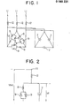
- Fig. 1 is a three-line connection diagram showing an embodiment of this invention, in which separate reactors 12 are respectively connected between the nodes of capacitors 7 and reactors 8, connected in parallel, and output terminals 11.
- Fig. 2 is a single-line connection diagram for explaining an embodiment of this invention.
- the apparatus can provide a phase leading reactive capacity of at most 1 P. U.
- the reactor 12 is assumed to be of 0,2 P. U.
- the capacitor 7 requires 1,2 P. U.
- V c V SVC holds at which the output of the apparatus is null.
- the reactive power of 1 P. U. can be controlled when the capacities of the reactor 8 and static switch means 9 are 0,833 P. U.
- the capacitor 7 it ordinarily supplies a reactive power smaller than the maximum phase leading reactive capacity, and only when the maximum phase leading reactive capacity is necessary, it can supply great reactive power owing to the rise of the voltage by the effect of the reactor 12. Therefore, a capacitor having a small rated power may be temporarily used under an overload condition.
- each of the capacitor 7, reactor 8 and static switch means 9 can have a small capacity, so that the miniaturization and economization of the apparatus can be achieved.
- Fig. 3 is a three-line connection diagram showing another embodiment of this invention.
- Transformers 13 each having three windings have primary windings connected to the output terminals 11 of a var compensator, secondary windings connected to static swithc means 9, and tertiary windings connected to capacitors 7.
- Fig. 4 is a single-line connection diagram of this other embodiment, in which the leakage impedances of the primary, secondary and tertiary windings of the transforder 13 are respectively denoted by Z1, Z2 and Z3.
- the impedance Z1 performs a function corresponding to the reactor 12 in Fig. 2
- the impedance Z2 is endowed with a comparatively great impedance and performs a function corresponding to the reactor 8 in Fig. 2 (the quantity by which it consumes reactive power is controlled by the static swithc means 9)
- the impedance Z3 is endowed with a substantially null impedance.
- the transformer 13 can be substituted for the two reactors as described,above, and moreover, the secondary voltage and tertiary voltage of the transformer 13 can be respectively set at any desired voltage permitting the static switch means 9 and capacitor 7 to be constructed most economically, so that an apparatus or a circuit can be provided which is economical and the installation area of which is small.
- a separate reactor is connected between the corresponding node of a reactor and a capacitor on the one hand, and an output terminal on the other hand, whereby the capacities of the capacitor, the reactor and static switch means can be rendered small, to bring forth the effect that a small-sized and inexpensive apparatus can be fabricated.
Landscapes
- Engineering & Computer Science (AREA)
- Power Engineering (AREA)
- Control Of Electrical Variables (AREA)
- Supply And Distribution Of Alternating Current (AREA)
Applications Claiming Priority (2)
| Application Number | Priority Date | Filing Date | Title |
|---|---|---|---|
| JP228867/84 | 1984-11-01 | ||
| JP59228867A JPS61109426A (ja) | 1984-11-01 | 1984-11-01 | 静止形無効電力補償装置 |
Publications (4)
| Publication Number | Publication Date |
|---|---|
| EP0180231A2 true EP0180231A2 (fr) | 1986-05-07 |
| EP0180231A3 EP0180231A3 (en) | 1988-03-16 |
| EP0180231B1 EP0180231B1 (fr) | 1993-01-13 |
| EP0180231B2 EP0180231B2 (fr) | 1997-11-05 |
Family
ID=16883118
Family Applications (1)
| Application Number | Title | Priority Date | Filing Date |
|---|---|---|---|
| EP85113883A Expired - Lifetime EP0180231B2 (fr) | 1984-11-01 | 1985-10-31 | Circuit statique de compensation d'énergie réactive |
Country Status (4)
| Country | Link |
|---|---|
| US (1) | US4686447A (fr) |
| EP (1) | EP0180231B2 (fr) |
| JP (1) | JPS61109426A (fr) |
| DE (1) | DE3586982T3 (fr) |
Cited By (1)
| Publication number | Priority date | Publication date | Assignee | Title |
|---|---|---|---|---|
| EP2559129A1 (fr) | 2010-04-14 | 2013-02-20 | Alstom Grid Oy | Agencement et procédé de compensation de la puissance réactive |
Families Citing this family (16)
| Publication number | Priority date | Publication date | Assignee | Title |
|---|---|---|---|---|
| US5548203A (en) * | 1994-06-29 | 1996-08-20 | Electric Power Research Institute, Inc. | Capacitor polarity-based var correction controller for resonant line conditions and large amplitude line harmonics |
| JP2795183B2 (ja) * | 1994-08-08 | 1998-09-10 | 松下電器産業株式会社 | 静止形無効電力補償装置 |
| SE510197C2 (sv) * | 1997-02-06 | 1999-04-26 | Asea Brown Boveri | Förfarande och anordning för styrning av ett kondensatordon för en shuntkopplad statisk kompensatorenhet med deblockeringssignaler för indikering av icke strömförande tillstånd hos ingående ventiler |
| GB2322981B (en) * | 1997-03-07 | 2001-02-21 | Cegelec Controls Ltd | Power supply circuits |
| US7514907B2 (en) * | 2005-05-24 | 2009-04-07 | Satcon Technology Corporation | Device, system, and method for providing a low-voltage fault ride-through for a wind generator farm |
| JP4820220B2 (ja) * | 2006-06-28 | 2011-11-24 | 三菱電機株式会社 | 静止形無効電力補償装置の制御方式 |
| EP2147492A2 (fr) * | 2007-05-18 | 2010-01-27 | ABB Technology AG | Appareil statique de compensateur de var |
| ES2340348B1 (es) * | 2008-01-04 | 2011-01-17 | Corporacion Zigor, S.A. | Dispositivo para la correccion del factor de potencia con variacion continua de potencia reactiva. |
| EP2443717B1 (fr) * | 2009-06-18 | 2013-12-04 | ABB Technology AG | Dispositif pour echanger de l'energie |
| CN102227085B (zh) * | 2011-06-18 | 2016-03-30 | 赵忠臣 | Lc调谐式静止无功发生器 |
| KR101156068B1 (ko) | 2012-02-13 | 2012-06-20 | 진정욱 | 안경 코받침대 |
| JP5959343B2 (ja) * | 2012-07-09 | 2016-08-02 | 三菱電機株式会社 | 静止形無効電力補償装置 |
| CN102904264B (zh) * | 2012-09-29 | 2015-09-16 | 浙江紫光电器有限公司 | 一种高压无功自动补偿装置 |
| CN104037782B (zh) * | 2014-05-29 | 2016-08-31 | 南方电网科学研究院有限责任公司 | 一种抑制小水电引起低频振荡的静止无功补偿器配置方法 |
| UA109619C2 (uk) * | 2014-10-13 | 2015-09-10 | Пристрій регулювання реактивної потужності електричної мережі (варіанти) | |
| KR101717367B1 (ko) * | 2015-08-19 | 2017-03-16 | 엘에스산전 주식회사 | 정적 무효전력 보상 장치 및 그 동작 방법 |
Family Cites Families (5)
| Publication number | Priority date | Publication date | Assignee | Title |
|---|---|---|---|---|
| SE378719B (fr) * | 1973-12-13 | 1975-09-08 | Asea Ab | |
| JPS5437243A (en) * | 1977-08-29 | 1979-03-19 | Mitsubishi Electric Corp | Compensating device of reactive power |
| SU741369A1 (ru) * | 1978-01-05 | 1980-06-15 | Институт Электродинамики Ан Украинской Сср | Устройство дл повышени качества напр жени многофазной сети переменного тока |
| EP0026260B1 (fr) * | 1979-09-27 | 1984-03-28 | Siemens Aktiengesellschaft | Dispositif de régulation de la tension entre deux conducteurs d'un réseau d'alimentation à courant alternatif pour une charge variant rapidement |
| DE3030784C2 (de) * | 1980-08-14 | 1986-09-11 | Licentia Patent-Verwaltungs-Gmbh, 6000 Frankfurt | Schaltungsanordnung zur schnellen Blindleistungskompensation mit einem Transformator |
-
1984
- 1984-11-01 JP JP59228867A patent/JPS61109426A/ja active Pending
-
1985
- 1985-10-04 US US06/784,043 patent/US4686447A/en not_active Expired - Lifetime
- 1985-10-31 DE DE3586982T patent/DE3586982T3/de not_active Expired - Fee Related
- 1985-10-31 EP EP85113883A patent/EP0180231B2/fr not_active Expired - Lifetime
Cited By (2)
| Publication number | Priority date | Publication date | Assignee | Title |
|---|---|---|---|---|
| EP2559129A1 (fr) | 2010-04-14 | 2013-02-20 | Alstom Grid Oy | Agencement et procédé de compensation de la puissance réactive |
| US9257844B2 (en) | 2010-04-14 | 2016-02-09 | Alstom Grid Oy | Arrangement and method for reactive power compensation |
Also Published As
| Publication number | Publication date |
|---|---|
| JPS61109426A (ja) | 1986-05-27 |
| US4686447A (en) | 1987-08-11 |
| DE3586982T3 (de) | 1998-05-28 |
| DE3586982T2 (de) | 1993-05-06 |
| EP0180231B2 (fr) | 1997-11-05 |
| DE3586982D1 (de) | 1993-02-25 |
| EP0180231B1 (fr) | 1993-01-13 |
| EP0180231A3 (en) | 1988-03-16 |
Similar Documents
| Publication | Publication Date | Title |
|---|---|---|
| EP0180231A2 (fr) | Circuit statique de compensation d'énergie réactive | |
| US5073848A (en) | Power distribution system | |
| US5397927A (en) | Active filter for reducing non-fundamental currents and voltages | |
| EP0157282B1 (fr) | Circuit d'alimentation électrique permettant de réduire une perte de puissance électrique | |
| US5610501A (en) | Dynamic power and voltage regulator for an ac transmission line | |
| US4999759A (en) | Multiple output switching power supply having one controlled output voltage and load compensation | |
| US6545453B2 (en) | Systems and methods for providing voltage regulation externally to a power transformer | |
| CA2323659C (fr) | Methode et systeme de suppression d'une fluctuation de tension dans un systeme d'alimentation | |
| US5900723A (en) | Voltage based VAR compensation system | |
| WO1994005067A9 (fr) | Filtre actif de reduction de courants et de tensions non fondamentaux | |
| EP0239278A2 (fr) | Appareil capacitif pour la compensation de puissance réactive | |
| US4320444A (en) | Control of a HVT (high voltage D-C transmission) short coupler | |
| US4339705A (en) | Thyristor switched inductor circuit for regulating voltage | |
| US3842342A (en) | Voltage stabilising arrangements | |
| US4558229A (en) | Series ferroresonant regulated rectifier with added capacitor shunting the saturating reactor winding | |
| US3697856A (en) | Voltage regulating circuit | |
| US1755060A (en) | Automatic voltage-regulating means | |
| US3440516A (en) | Transformer and capacitor apparatus for three-phase electrical systems | |
| CA1183895A (fr) | Systeme pour reduire les exigences en termes de puissance nominale pour les composantes statique d'un poste redresseur de courant continu haute tension | |
| JP3480123B2 (ja) | 発電設備を有する電源系統の無効電力等の補償方式 | |
| SU1591088A1 (ru) | Бесконтактное устройство для регулирования напряжения трехфазного силового трансформатора | |
| KR200237460Y1 (ko) | 자동전압조절 기능을 갖는 라인 인터액티브 무정전전원장치 | |
| JPS5837717A (ja) | 電源装置の出力保持時間補償回路 | |
| CN119813273B (zh) | 定制电力智能输出的电压平衡装置及交流低压配电系统 | |
| JP3319216B2 (ja) | 定電圧高調波吸収電源装置 |
Legal Events
| Date | Code | Title | Description |
|---|---|---|---|
| PUAI | Public reference made under article 153(3) epc to a published international application that has entered the european phase |
Free format text: ORIGINAL CODE: 0009012 |
|
| AK | Designated contracting states |
Kind code of ref document: A2 Designated state(s): CH DE LI SE |
|
| PUAL | Search report despatched |
Free format text: ORIGINAL CODE: 0009013 |
|
| AK | Designated contracting states |
Kind code of ref document: A3 Designated state(s): CH DE LI SE |
|
| 17P | Request for examination filed |
Effective date: 19880422 |
|
| 17Q | First examination report despatched |
Effective date: 19900417 |
|
| GRAA | (expected) grant |
Free format text: ORIGINAL CODE: 0009210 |
|
| AK | Designated contracting states |
Kind code of ref document: B1 Designated state(s): CH DE LI SE |
|
| REF | Corresponds to: |
Ref document number: 3586982 Country of ref document: DE Date of ref document: 19930225 |
|
| PLBI | Opposition filed |
Free format text: ORIGINAL CODE: 0009260 |
|
| 26 | Opposition filed |
Opponent name: ASEA BROWN BOVERI AB Effective date: 19931012 |
|
| EAL | Se: european patent in force in sweden |
Ref document number: 85113883.4 |
|
| PLAW | Interlocutory decision in opposition |
Free format text: ORIGINAL CODE: EPIDOS IDOP |
|
| PLAW | Interlocutory decision in opposition |
Free format text: ORIGINAL CODE: EPIDOS IDOP |
|
| PUAH | Patent maintained in amended form |
Free format text: ORIGINAL CODE: 0009272 |
|
| STAA | Information on the status of an ep patent application or granted ep patent |
Free format text: STATUS: PATENT MAINTAINED AS AMENDED |
|
| 27A | Patent maintained in amended form |
Effective date: 19971105 |
|
| AK | Designated contracting states |
Kind code of ref document: B2 Designated state(s): CH DE LI SE |
|
| REG | Reference to a national code |
Ref country code: CH Ref legal event code: AEN Free format text: AUFRECHTERHALTUNG DES PATENTES IN GEAENDERTER FORM |
|
| PGFP | Annual fee paid to national office [announced via postgrant information from national office to epo] |
Ref country code: SE Payment date: 19981006 Year of fee payment: 14 |
|
| PGFP | Annual fee paid to national office [announced via postgrant information from national office to epo] |
Ref country code: DE Payment date: 19981106 Year of fee payment: 14 |
|
| PGFP | Annual fee paid to national office [announced via postgrant information from national office to epo] |
Ref country code: CH Payment date: 19981113 Year of fee payment: 14 |
|
| PG25 | Lapsed in a contracting state [announced via postgrant information from national office to epo] |
Ref country code: LI Free format text: LAPSE BECAUSE OF NON-PAYMENT OF DUE FEES Effective date: 19991031 Ref country code: CH Free format text: LAPSE BECAUSE OF NON-PAYMENT OF DUE FEES Effective date: 19991031 |
|
| PG25 | Lapsed in a contracting state [announced via postgrant information from national office to epo] |
Ref country code: SE Free format text: LAPSE BECAUSE OF NON-PAYMENT OF DUE FEES Effective date: 19991101 |
|
| REG | Reference to a national code |
Ref country code: CH Ref legal event code: PL |
|
| EUG | Se: european patent has lapsed |
Ref document number: 85113883.4 |
|
| PG25 | Lapsed in a contracting state [announced via postgrant information from national office to epo] |
Ref country code: DE Free format text: LAPSE BECAUSE OF NON-PAYMENT OF DUE FEES Effective date: 20000801 |