EP0180329A1 - Fallschirm - Google Patents
Fallschirm Download PDFInfo
- Publication number
- EP0180329A1 EP0180329A1 EP85306951A EP85306951A EP0180329A1 EP 0180329 A1 EP0180329 A1 EP 0180329A1 EP 85306951 A EP85306951 A EP 85306951A EP 85306951 A EP85306951 A EP 85306951A EP 0180329 A1 EP0180329 A1 EP 0180329A1
- Authority
- EP
- European Patent Office
- Prior art keywords
- canopy
- parachute
- ram air
- parachute according
- cells
- Prior art date
- Legal status (The legal status is an assumption and is not a legal conclusion. Google has not performed a legal analysis and makes no representation as to the accuracy of the status listed.)
- Granted
Links
- 239000000725 suspension Substances 0.000 claims 6
- 239000003570 air Substances 0.000 description 15
- 239000004744 fabric Substances 0.000 description 2
- 230000006978 adaptation Effects 0.000 description 1
- 239000012080 ambient air Substances 0.000 description 1
- 230000000740 bleeding effect Effects 0.000 description 1
- 230000000295 complement effect Effects 0.000 description 1
- 230000005484 gravity Effects 0.000 description 1
- 238000000926 separation method Methods 0.000 description 1
Images


Classifications
-
- B—PERFORMING OPERATIONS; TRANSPORTING
- B64—AIRCRAFT; AVIATION; COSMONAUTICS
- B64D—EQUIPMENT FOR FITTING IN OR TO AIRCRAFT; FLIGHT SUITS; PARACHUTES; ARRANGEMENT OR MOUNTING OF POWER PLANTS OR PROPULSION TRANSMISSIONS IN AIRCRAFT
- B64D19/00—Non-canopied parachutes
-
- B—PERFORMING OPERATIONS; TRANSPORTING
- B64—AIRCRAFT; AVIATION; COSMONAUTICS
- B64D—EQUIPMENT FOR FITTING IN OR TO AIRCRAFT; FLIGHT SUITS; PARACHUTES; ARRANGEMENT OR MOUNTING OF POWER PLANTS OR PROPULSION TRANSMISSIONS IN AIRCRAFT
- B64D17/00—Parachutes
- B64D17/02—Canopy arrangement or construction
- B64D17/025—Canopy arrangement or construction for gliding chutes
Definitions
- the present invention relates to a parachute.
- the objective of efficient parachute design is to minimize the area of cloth used in the canopy to give a certain rate of descent for a given suspended load. Accordingly a more efficient parachute is one which has an increased load capacity for the same canopy cloth area and the same rate of descent in comparison with another parachute.
- a known form of parachute which has a load capacity increased from a conventional parachute is a ram air parachute.
- the first such parachute was described in the specification of US Patent No. 3,285,546, reissued under No. 26,427 in the name of Domina C. Jalbert.
- Various proposals have been made for improving ram air parachutes, in particular as described in the specification of US Patent No. 3,724,789 in the name of Stephen L. Snyder.
- the canopy of a ram air parachute includes channels or cells into which air is “rammed” in “flight”. This ram air inflates the cells and causes the canopy to be shaped, in accordance with the cut of it including the cells.
- the shaped canopy is an aerofoil. The canopy is so arranged, under the control of the lines to the load supported thereby, that in descending under gravity it "flies" forwards. The aerofoil canopy then generates lift increasing the load capacity of the canopy.
- a disadvantage of a ram air parachute can be that it does have its considerable forward velocity in flight. This restricts its usefulness in some applications, although it can be useful in other applications.
- parachutists use a ram air parachute, they can brake the forward velocity by stalling the flight for landing. This requirement is disadvantageous for inanimate loads.
- the object of the present invention is to provide a more efficient parachute.
- the parachute of the invention includes means whereby its canopy is caused to rotate about a substantially vertical axis when in use and means for creating aerodynamic lift on the canopy as a result of the rotation.
- the lift increases the load capacity of the parachute.
- the preferred parachute of the present invention is in the form of two discrete oppositely facing diametrally connected ram air sections. In use, the two sections rotate and have a forward velocity relative to the ambient air but no nett forward velocity over the ground, except of course any such velocity resulting from wind. More than two, angularly spaced sections may be used.
- the canopy of the parachute of the invention is preferably diametrally elongate, with a substantially constant width corresponding to a small circumferential distance at diametral ends of the canopy.
- the canopy is curved in its diametral direction whereby the lines can be connected to it at right angles to its local tangent in the diametral direction.
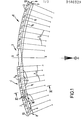
- the drawings show the parachute fully deployed in use.
- the parachute has a canopy 1 comprised of two sections 1', 1", each having an upper skin 2 and a lower skin 3.
- the sections are connected by a central lower skin portion 3'.
- the skins are interconnected by a number of ribs 4.
- the skins are separate at their front edges 5 u , 5 1 and stitched together at their trailing edges 6.
- the ribs 4 give each upper skin 2 an upper aerofoil surface shape.
- Each lower skin 3 has its shape - which is locally flat but slopes up from front edge 5 1 to rear edge 6 - determined by the parachute lines 7 and the ribs 4.
- the lines 7 are connected to the feet of the ribs 4 so as to tension them when the upper skin 2 draws the ribs up.
- the ribs 4 divide the canopy sections between the skins 2,3 into a number of cells C 1 , C 2 , C 3 ... C 151 C 16 across the diametral extent of the canopy from one diametral end 8 thereof to the other diametral end 9.
- the canopy 1 rotates as will be described in more detail below.
- the-outer cells C 1 , C 2 , C 3' C 4' C 13' C 14' C 15 , C 16 have open mouths 10 at their forward ends 5.
- the other, inner cells are closed by walls 11 at their forward ends 5. All the cells are closed at the stitching together of the rear edges 6 of upper and lower skins.
- the ribs 4 between the inner-most outer cells C 4 , C 13 have centrally positioned openings 12 for bleeding air from cells C 4 & C 13 to cells C 5 & C 12 respectively. Similar openings bleed air through successively to cells C6, C 7 and C 8 from cell C 5 and to cells C 11 , C 10 and C 9 from cell C 12 .
- Outer walls 13 are provided to cells C 1 & C 16 at the diametral ends 8 and 9 of the canopy 1.
- Inner end walls 14 are provided to the cells C 8 , C 9 at the inner ends of the sections 1', 1".
- a swivel 15 is provided between the lines 7 and a payload (not shown) so that the latter does not rotate when the former does.
- the upper skin 2 will then take up its aerofoil shape, of which the ridge 16 is shown in Figure 2 as a chain dotted line.
- the fully deployed shape of the canopy is generally circularly curved about the swivel 15 - as viewed in side elevation as shown in Figure 1.. With this shape, the lines are connected to the canopy at right angles, the local tangent to the canopy extending radially from the axis X-X. This connection avoids any tendency for the canopy to be urged laterally by the tension in the lines.
- This curved shape is achieved by the lines 7 being all of approximately the same length from the swivel, those connected successively further towards the rear edge 6 being successively slightly longer to enable the lower skins to slope upwards from front to rear - causing the canopy to rotate as mentioned.
- the air flow past the aerofoil shape will create lift which will slow descent of the parachute.
- the result is that the load capacity of the parachute will be greatly in excess of that of a conventional parachute having the same canopy area. Lacking nett forward velocity the parachute will descend reasonably straight down.
- the lower skin portion 3' inter-connecting the sections 1', 1" of the canopy may be replaced by rigging lines or alternatively the sections may be jointed together at respective points and these points each connected.independently to the swivel 15.
- the single opening 12 may be replaced by a plurality of smaller openings in the ribs concerned.
Landscapes
- Engineering & Computer Science (AREA)
- Aviation & Aerospace Engineering (AREA)
- Toys (AREA)
- Lubricants (AREA)
Priority Applications (1)
| Application Number | Priority Date | Filing Date | Title |
|---|---|---|---|
| AT85306951T ATE39100T1 (de) | 1984-10-05 | 1985-09-30 | Fallschirm. |
Applications Claiming Priority (2)
| Application Number | Priority Date | Filing Date | Title |
|---|---|---|---|
| GB8425287 | 1984-10-05 | ||
| GB848425287A GB8425287D0 (en) | 1984-10-05 | 1984-10-05 | Parachute |
Publications (2)
| Publication Number | Publication Date |
|---|---|
| EP0180329A1 true EP0180329A1 (de) | 1986-05-07 |
| EP0180329B1 EP0180329B1 (de) | 1988-12-07 |
Family
ID=10567798
Family Applications (1)
| Application Number | Title | Priority Date | Filing Date |
|---|---|---|---|
| EP85306951A Expired EP0180329B1 (de) | 1984-10-05 | 1985-09-30 | Fallschirm |
Country Status (5)
| Country | Link |
|---|---|
| US (1) | US4662589A (de) |
| EP (1) | EP0180329B1 (de) |
| AT (1) | ATE39100T1 (de) |
| DE (1) | DE3566654D1 (de) |
| GB (1) | GB8425287D0 (de) |
Families Citing this family (13)
| Publication number | Priority date | Publication date | Assignee | Title |
|---|---|---|---|---|
| US5153371A (en) * | 1992-02-10 | 1992-10-06 | The United States Of America As Represented By The Secretary Of The Army | Ribbon stabilizer for a weapon |
| FR2769287B1 (fr) * | 1997-10-08 | 1999-12-24 | Lacroix Soc E | Dispositif de freinage de la chute d'une charge |
| US7059570B2 (en) * | 2004-04-20 | 2006-06-13 | Edward Strong | Aerial delivery device |
| US20090026319A1 (en) * | 2004-04-20 | 2009-01-29 | Edward Strong | Aerial delivery system |
| WO2007089231A1 (en) * | 2006-02-02 | 2007-08-09 | Fox Roy L Jr | Semi-cylindrical type parachute |
| RU2526113C1 (ru) * | 2013-06-18 | 2014-08-20 | Виктор Степанович Ермоленко | Система управления вращающимся парашютом |
| RU2682947C1 (ru) * | 2018-02-05 | 2019-03-22 | Общество с ограниченной ответственностью Фирма "Передовые технологии парашютостроения" | Вращающийся парашют |
| US11186376B2 (en) * | 2018-03-05 | 2021-11-30 | The Government Of The United States, As Represented By The Secretary Of The Army | Aerial delivery system |
| TWI666146B (zh) * | 2018-08-07 | 2019-07-21 | 崑山科技大學 | Easy to deploy parachute and umbrella bag |
| RU2712382C1 (ru) * | 2018-11-30 | 2020-01-28 | Общество с ограниченной ответственностью Фирма "Передовые технологии парашютостроения" | Вращающийся парашют |
| RU2707482C1 (ru) * | 2018-11-30 | 2019-11-26 | Общество с ограниченной ответственностью Фирма "Передовые технологии парашютостроения" | Вращающийся парашют |
| RU2707165C1 (ru) * | 2018-11-30 | 2019-11-22 | Общество с ограниченной ответственностью Фирма "Передовые технологии парашютостроения" | Вращающийся парашют |
| ES2774849A1 (es) * | 2019-01-22 | 2020-07-22 | Jaime Hernandez Ignacio De | Paracaidas rotatorio |
Citations (3)
| Publication number | Priority date | Publication date | Assignee | Title |
|---|---|---|---|---|
| US3401906A (en) * | 1966-05-03 | 1968-09-17 | Ryan Aeronautical Co | Gyrochute |
| US3822844A (en) * | 1973-06-25 | 1974-07-09 | Jack Sutton | Parachute |
| GB1439389A (en) * | 1973-09-14 | 1976-06-16 | Steinthal & Co M | Rotating parachute |
Family Cites Families (5)
| Publication number | Priority date | Publication date | Assignee | Title |
|---|---|---|---|---|
| USRE26427E (en) | 1968-07-16 | Multi-cell wing type aerial device | ||
| US26427A (en) * | 1859-12-13 | Improvement in preserving flesh and meats | ||
| DE660793C (de) * | 1935-04-16 | 1938-06-02 | Ludwig Schart | Rettungs- und Lastenfallschraube mit unstarren Fluegeln |
| US2614636A (en) * | 1947-04-12 | 1952-10-21 | Richard H Prewitt | Rotor parachute |
| US3118641A (en) * | 1961-03-30 | 1964-01-21 | David T Barish | Auto-rotating parachute and swivel |
-
1984
- 1984-10-05 GB GB848425287A patent/GB8425287D0/en active Pending
-
1985
- 1985-09-18 US US06/777,098 patent/US4662589A/en not_active Expired - Fee Related
- 1985-09-30 DE DE8585306951T patent/DE3566654D1/de not_active Expired
- 1985-09-30 AT AT85306951T patent/ATE39100T1/de not_active IP Right Cessation
- 1985-09-30 EP EP85306951A patent/EP0180329B1/de not_active Expired
Patent Citations (3)
| Publication number | Priority date | Publication date | Assignee | Title |
|---|---|---|---|---|
| US3401906A (en) * | 1966-05-03 | 1968-09-17 | Ryan Aeronautical Co | Gyrochute |
| US3822844A (en) * | 1973-06-25 | 1974-07-09 | Jack Sutton | Parachute |
| GB1439389A (en) * | 1973-09-14 | 1976-06-16 | Steinthal & Co M | Rotating parachute |
Also Published As
| Publication number | Publication date |
|---|---|
| ATE39100T1 (de) | 1988-12-15 |
| EP0180329B1 (de) | 1988-12-07 |
| US4662589A (en) | 1987-05-05 |
| GB8425287D0 (en) | 1984-11-14 |
| DE3566654D1 (en) | 1989-01-12 |
Similar Documents
| Publication | Publication Date | Title |
|---|---|---|
| US4662589A (en) | Parachute | |
| US6322021B1 (en) | Deployable wing with propulsion for range extension | |
| US3524613A (en) | Flexible gliding wing | |
| US5474257A (en) | Deployable wing | |
| US5878979A (en) | Method and apparatus for landing a wing | |
| US3433441A (en) | Flexible aerodynamic body | |
| US3796398A (en) | In-flight aircraft recovery system | |
| US4811920A (en) | Aerial device | |
| US20100163682A1 (en) | Hybrid Parachute | |
| US6565041B1 (en) | Parachute assembly for a miniature aircraft | |
| EP0770545B1 (de) | Verfahren und Vorrichtung für ausklappbare Flügelflächen | |
| US6164594A (en) | Device for braking the fall of a load | |
| AU2005237144B2 (en) | Cruciform parachute with arms attached | |
| US5890678A (en) | Device to control inflation characteristics of parachutes | |
| US4540145A (en) | Reefing system | |
| US4863119A (en) | Parachute reefing system | |
| US3972495A (en) | Aerial sled | |
| US4955564A (en) | Main parachute apparatus with secondary parachute for aiding initial inflation thereof | |
| US4930726A (en) | Built-in control flaps for a multi-cell wing type canopy | |
| USRE31205E (en) | Aerial sled | |
| US3838940A (en) | Deployable rotor | |
| US5069404A (en) | Elliptical ram air pressurized airfoil parachute | |
| US3301511A (en) | Wing deployment method and apparatus | |
| EP1752378B1 (de) | Gleiter für Fallschirme durch mehrere Ösen gehalten | |
| US2970795A (en) | Bi-area pilot parachute |
Legal Events
| Date | Code | Title | Description |
|---|---|---|---|
| PUAI | Public reference made under article 153(3) epc to a published international application that has entered the european phase |
Free format text: ORIGINAL CODE: 0009012 |
|
| AK | Designated contracting states |
Kind code of ref document: A1 Designated state(s): AT BE CH DE FR GB IT LI NL SE |
|
| 17P | Request for examination filed |
Effective date: 19861020 |
|
| 17Q | First examination report despatched |
Effective date: 19870710 |
|
| GRAA | (expected) grant |
Free format text: ORIGINAL CODE: 0009210 |
|
| AK | Designated contracting states |
Kind code of ref document: B1 Designated state(s): AT BE CH DE FR GB IT LI NL SE |
|
| PG25 | Lapsed in a contracting state [announced via postgrant information from national office to epo] |
Ref country code: SE Effective date: 19881207 Ref country code: NL Effective date: 19881207 Ref country code: LI Effective date: 19881207 Ref country code: IT Free format text: LAPSE BECAUSE OF FAILURE TO SUBMIT A TRANSLATION OF THE DESCRIPTION OR TO PAY THE FEE WITHIN THE PRESCRIBED TIME-LIMIT;WARNING: LAPSES OF ITALIAN PATENTS WITH EFFECTIVE DATE BEFORE 2007 MAY HAVE OCCURRED AT ANY TIME BEFORE 2007. THE CORRECT EFFECTIVE DATE MAY BE DIFFERENT FROM THE ONE RECORDED. Effective date: 19881207 Ref country code: CH Effective date: 19881207 Ref country code: BE Effective date: 19881207 Ref country code: AT Effective date: 19881207 |
|
| REF | Corresponds to: |
Ref document number: 39100 Country of ref document: AT Date of ref document: 19881215 Kind code of ref document: T |
|
| REF | Corresponds to: |
Ref document number: 3566654 Country of ref document: DE Date of ref document: 19890112 |
|
| ET | Fr: translation filed | ||
| REG | Reference to a national code |
Ref country code: CH Ref legal event code: PL |
|
| NLV1 | Nl: lapsed or annulled due to failure to fulfill the requirements of art. 29p and 29m of the patents act | ||
| PLBE | No opposition filed within time limit |
Free format text: ORIGINAL CODE: 0009261 |
|
| STAA | Information on the status of an ep patent application or granted ep patent |
Free format text: STATUS: NO OPPOSITION FILED WITHIN TIME LIMIT |
|
| 26N | No opposition filed | ||
| PGFP | Annual fee paid to national office [announced via postgrant information from national office to epo] |
Ref country code: GB Payment date: 19900828 Year of fee payment: 6 |
|
| PGFP | Annual fee paid to national office [announced via postgrant information from national office to epo] |
Ref country code: DE Payment date: 19900914 Year of fee payment: 6 |
|
| PGFP | Annual fee paid to national office [announced via postgrant information from national office to epo] |
Ref country code: FR Payment date: 19900921 Year of fee payment: 6 |
|
| PG25 | Lapsed in a contracting state [announced via postgrant information from national office to epo] |
Ref country code: GB Effective date: 19910930 |
|
| GBPC | Gb: european patent ceased through non-payment of renewal fee | ||
| PG25 | Lapsed in a contracting state [announced via postgrant information from national office to epo] |
Ref country code: FR Effective date: 19920529 |
|
| PG25 | Lapsed in a contracting state [announced via postgrant information from national office to epo] |
Ref country code: DE Effective date: 19920602 |
|
| REG | Reference to a national code |
Ref country code: FR Ref legal event code: ST |