EP0180349A2 - Vorschubmechanismus für Holzbearbeitungsmaschinerie - Google Patents
Vorschubmechanismus für Holzbearbeitungsmaschinerie Download PDFInfo
- Publication number
- EP0180349A2 EP0180349A2 EP85307145A EP85307145A EP0180349A2 EP 0180349 A2 EP0180349 A2 EP 0180349A2 EP 85307145 A EP85307145 A EP 85307145A EP 85307145 A EP85307145 A EP 85307145A EP 0180349 A2 EP0180349 A2 EP 0180349A2
- Authority
- EP
- European Patent Office
- Prior art keywords
- roller
- arm
- fence
- shaft
- spring
- Prior art date
- Legal status (The legal status is an assumption and is not a legal conclusion. Google has not performed a legal analysis and makes no representation as to the accuracy of the status listed.)
- Granted
Links
Images

Classifications
-
- B—PERFORMING OPERATIONS; TRANSPORTING
- B27—WORKING OR PRESERVING WOOD OR SIMILAR MATERIAL; NAILING OR STAPLING MACHINES IN GENERAL
- B27B—SAWS FOR WOOD OR SIMILAR MATERIAL; COMPONENTS OR ACCESSORIES THEREFOR
- B27B25/00—Feeding devices for timber in saw mills or sawing machines; Feeding devices for trees
- B27B25/02—Feeding devices for timber in saw mills or sawing machines; Feeding devices for trees with feed and pressure rollers
-
- Y—GENERAL TAGGING OF NEW TECHNOLOGICAL DEVELOPMENTS; GENERAL TAGGING OF CROSS-SECTIONAL TECHNOLOGIES SPANNING OVER SEVERAL SECTIONS OF THE IPC; TECHNICAL SUBJECTS COVERED BY FORMER USPC CROSS-REFERENCE ART COLLECTIONS [XRACs] AND DIGESTS
- Y10—TECHNICAL SUBJECTS COVERED BY FORMER USPC
- Y10T—TECHNICAL SUBJECTS COVERED BY FORMER US CLASSIFICATION
- Y10T83/00—Cutting
- Y10T83/647—With means to convey work relative to tool station
- Y10T83/6492—Plural passes of diminishing work piece through tool station
- Y10T83/6494—Work alternately, angularly re-oriented relative to tool station
- Y10T83/6497—By roller or roll-like element
-
- Y—GENERAL TAGGING OF NEW TECHNOLOGICAL DEVELOPMENTS; GENERAL TAGGING OF CROSS-SECTIONAL TECHNOLOGIES SPANNING OVER SEVERAL SECTIONS OF THE IPC; TECHNICAL SUBJECTS COVERED BY FORMER USPC CROSS-REFERENCE ART COLLECTIONS [XRACs] AND DIGESTS
- Y10—TECHNICAL SUBJECTS COVERED BY FORMER USPC
- Y10T—TECHNICAL SUBJECTS COVERED BY FORMER US CLASSIFICATION
- Y10T83/00—Cutting
- Y10T83/647—With means to convey work relative to tool station
- Y10T83/6584—Cut made parallel to direction of and during work movement
- Y10T83/6635—By feed roller
- Y10T83/6636—Pinch rollers
-
- Y—GENERAL TAGGING OF NEW TECHNOLOGICAL DEVELOPMENTS; GENERAL TAGGING OF CROSS-SECTIONAL TECHNOLOGIES SPANNING OVER SEVERAL SECTIONS OF THE IPC; TECHNICAL SUBJECTS COVERED BY FORMER USPC CROSS-REFERENCE ART COLLECTIONS [XRACs] AND DIGESTS
- Y10—TECHNICAL SUBJECTS COVERED BY FORMER USPC
- Y10T—TECHNICAL SUBJECTS COVERED BY FORMER US CLASSIFICATION
- Y10T83/00—Cutting
- Y10T83/727—With means to guide moving work
- Y10T83/741—With movable or yieldable guide element
Definitions
- the invention relates to mechanism whereby timber is fed to machinery such as rip saws.
- Rip saws are customarily provided with powered feed rollers to drive timber workpieces along a fence and past a band saw blade.
- the positions of the feed rollers and fence relative to the blade are each adjustable by means of a handwheel and screw.
- the feed rollers are biassed towards the fence by means of a spring or weights or hydraulically. This allows a certain amount of variation, perhaps,25 mm in the width of the workpiece fed.
- the problem is to allow a greater variation in the width of the workpiece without the need to reposition the feed mechanism.
- a workpiece may be put through a machine a number of times, and reduced in width at each pass. The invention reduces the frequency at which it is necessary to adjust the position of the feed mechanism.
- the invention provides feed mechanism for woodworking machinery comprising a roller for driving a workpiece along a fence and through the machine, power means for rotating the roller in relation to an arm, an upright shaft about which the arm is pivotable, and a spring biassing the arm so that the roller is urged towards the fence.
- the spring is preferably coiled around the upright shaft, fastened at one end to an adjustable stop and at the other end to a collar locked to the shaft.
- the power means preferably comprises a chain drive from a motor to the roller via a double sprocket freely rotatable on the upright shaft. This makes it possible to gear down the rotational speed of the drive and avoid the use of a chain tensioner.
- the force of the spring makes the feed roller engage a wide workpiece strongly, and so increases its tractive effect.
- the saw comprises feed rollers 10 for driving a workpiece (not shown) along a fence 12 towards a blade 14.
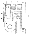
- the section in Figure 3 shows in greater detail how an electric motor 16 rotates the rollers 10 through chain 18, 19 via a double sprocket 20 freely rotatable at the top of an upright shaft 22.
- the rollers 10 are secured on a shaft 24 which is rotatably journalled in an arm 26 and driven through a chain sprocket 28.
- the arm 26 is locked fast on the upright shaft 22, so the rollers 10 are rotated in relation to the arm 26.
- the arm 26 is pivotable through about 90 0 , rotatably mounted in bushes in a machine casing at its base and centre, and surrounded at its lower part by a coil spring 30.
- the coil spring 30 is fastened at a lower end to an adjustable stop 32 on the machine casing whereby the tension of the spring may be adjusted, and at its upper end to a collar 34 which is locked fast on the upright shaft 22.
- the coil spring 30 biasses the shaft 22 and the arm 26 anti-clockwise as it would appear in Figure 2 so that the rollers 10 are urged towards the fence 12 from a position B towards a position A.
- rollers 10 drive the workpiece along the fence 12 and through the machine.
- the wider and/or heavier the workpiece the greater the force applied by the coil spring 30 to move the workpiece towards the fence 12, and consequently the greater the tractive effect of the rollers 10.
Landscapes
- Life Sciences & Earth Sciences (AREA)
- Engineering & Computer Science (AREA)
- Mechanical Engineering (AREA)
- Wood Science & Technology (AREA)
- Forests & Forestry (AREA)
- Milling, Drilling, And Turning Of Wood (AREA)
- Crushing And Pulverization Processes (AREA)
- Chemical And Physical Treatments For Wood And The Like (AREA)
- Surgical Instruments (AREA)
- Vending Machines For Individual Products (AREA)
- Sawing (AREA)
Priority Applications (1)
| Application Number | Priority Date | Filing Date | Title |
|---|---|---|---|
| AT85307145T ATE75437T1 (de) | 1984-10-24 | 1985-10-07 | Vorschubmechanismus fuer holzbearbeitungsmaschinerie. |
Applications Claiming Priority (2)
| Application Number | Priority Date | Filing Date | Title |
|---|---|---|---|
| GB848426857A GB8426857D0 (en) | 1984-10-24 | 1984-10-24 | Feed mechanism |
| GB8426857 | 1984-10-24 |
Publications (3)
| Publication Number | Publication Date |
|---|---|
| EP0180349A2 true EP0180349A2 (de) | 1986-05-07 |
| EP0180349A3 EP0180349A3 (en) | 1987-07-15 |
| EP0180349B1 EP0180349B1 (de) | 1992-04-29 |
Family
ID=10568662
Family Applications (1)
| Application Number | Title | Priority Date | Filing Date |
|---|---|---|---|
| EP85307145A Expired - Lifetime EP0180349B1 (de) | 1984-10-24 | 1985-10-07 | Vorschubmechanismus für Holzbearbeitungsmaschinerie |
Country Status (5)
| Country | Link |
|---|---|
| US (1) | US4662413A (de) |
| EP (1) | EP0180349B1 (de) |
| AT (1) | ATE75437T1 (de) |
| DE (1) | DE3585941D1 (de) |
| GB (1) | GB8426857D0 (de) |
Cited By (1)
| Publication number | Priority date | Publication date | Assignee | Title |
|---|---|---|---|---|
| US20240042644A1 (en) * | 2022-08-08 | 2024-02-08 | Woodpeckers, Llc | Table saw jig and method of use |
Families Citing this family (4)
| Publication number | Priority date | Publication date | Assignee | Title |
|---|---|---|---|---|
| DE4305356C1 (de) * | 1993-02-20 | 1994-03-31 | Georg Aigner | Andruckvorrichtung für Holzfräsmaschinen |
| US5507330A (en) * | 1995-06-30 | 1996-04-16 | Chen; Chin-Te | Workpiece feeding device for an edge shaping apparatus |
| FI100576B (fi) * | 1996-07-17 | 1998-01-15 | Plustech Oy | Puunkorjuukoneen koura |
| AU2007211304B2 (en) * | 2006-01-30 | 2011-08-04 | Provo Craft And Novelty, Inc. | Roller die press |
Family Cites Families (9)
| Publication number | Priority date | Publication date | Assignee | Title |
|---|---|---|---|---|
| US401397A (en) * | 1889-04-16 | George f | ||
| CA571062A (en) * | 1959-02-24 | M. Copley Joseph | Edger-guide for trimming apparatus | |
| US126381A (en) * | 1872-05-07 | Improvement in planing-machines | ||
| FR1018378A (fr) * | 1950-04-13 | 1953-01-07 | Dispositif de sécurité pour les machines à travailler le bois | |
| DE910724C (de) * | 1952-07-29 | 1954-05-06 | Hermann Ambelang | Vorrichtung zur Fuehrung der Arbeitsstuecke auf Abrichtmaschinen |
| BE536738A (de) * | 1953-03-03 | |||
| US2804892A (en) * | 1954-09-13 | 1957-09-03 | Russell E Peterson | Work hold-down for jointers |
| CH351391A (de) * | 1957-04-04 | 1961-01-15 | Bruendler Arthur | Vorschubapparat zum Vorschieben von Schnittholz auf Abrichtmaschinen |
| US2998040A (en) * | 1959-05-01 | 1961-08-29 | Patterson Robert Glenn | Power feeds for edge planers |
-
1984
- 1984-10-24 GB GB848426857A patent/GB8426857D0/en active Pending
-
1985
- 1985-10-07 EP EP85307145A patent/EP0180349B1/de not_active Expired - Lifetime
- 1985-10-07 AT AT85307145T patent/ATE75437T1/de not_active IP Right Cessation
- 1985-10-07 DE DE8585307145T patent/DE3585941D1/de not_active Expired - Fee Related
-
1986
- 1986-10-28 US US06/925,519 patent/US4662413A/en not_active Expired - Fee Related
Cited By (2)
| Publication number | Priority date | Publication date | Assignee | Title |
|---|---|---|---|---|
| US20240042644A1 (en) * | 2022-08-08 | 2024-02-08 | Woodpeckers, Llc | Table saw jig and method of use |
| US12441022B2 (en) * | 2022-08-08 | 2025-10-14 | Woodpeckers, Llc | Table saw jig and method of use |
Also Published As
| Publication number | Publication date |
|---|---|
| GB8426857D0 (en) | 1984-11-28 |
| US4662413A (en) | 1987-05-05 |
| ATE75437T1 (de) | 1992-05-15 |
| DE3585941D1 (de) | 1992-06-04 |
| EP0180349B1 (de) | 1992-04-29 |
| EP0180349A3 (en) | 1987-07-15 |
Similar Documents
| Publication | Publication Date | Title |
|---|---|---|
| CA1047391A (en) | Method and apparatus for transverse cutting | |
| GB1503064A (en) | Portable power driven band saw | |
| US4436126A (en) | Wood planing machine | |
| US4127045A (en) | Band saw machine | |
| US3757625A (en) | Apparatus for making engineering stakes | |
| EP0180349A2 (de) | Vorschubmechanismus für Holzbearbeitungsmaschinerie | |
| EP1483089B1 (de) | Vorrichtung zum schneiden von holz ohne sägespäne | |
| US4604835A (en) | Apparatus for automatic maintenance of surface speed and work-bearing force for rotary tool apparatus | |
| CN217044852U (zh) | 一种圆盘带式组合切割锯装置 | |
| US3707999A (en) | Moving shadow light indexing means | |
| US4846023A (en) | Regrinding apparatus for circular saws | |
| US4173160A (en) | Machine for cutting the lead ends of components mounted at printed-wiring boards | |
| US4681005A (en) | Twin arbor resaw with a fence having a continuous rotatable belt | |
| CN214981357U (zh) | 一种弧形切割设备 | |
| US4510835A (en) | Apparatus for guiding a powered circular saw along an elliptical cutting path | |
| US3738208A (en) | Sawmill apparatus having an improved log carriage feed control | |
| US4193431A (en) | Fence slat cutting method and apparatus | |
| KR19980082126A (ko) | 볏짚 절단기 | |
| US4061070A (en) | Cant strip machine | |
| US4524663A (en) | Power hacksaw | |
| SU738873A1 (ru) | Многопильный ленточный станок | |
| CN219853457U (zh) | 一种带锯床的上料装置 | |
| US4909115A (en) | Apparatus for loading a band saw blade | |
| CN213379592U (zh) | 一种锯床的减震装置 | |
| KR910000515B1 (ko) | 기계톱 |
Legal Events
| Date | Code | Title | Description |
|---|---|---|---|
| PUAI | Public reference made under article 153(3) epc to a published international application that has entered the european phase |
Free format text: ORIGINAL CODE: 0009012 |
|
| AK | Designated contracting states |
Kind code of ref document: A2 Designated state(s): AT CH DE FR GB IT LI |
|
| PUAL | Search report despatched |
Free format text: ORIGINAL CODE: 0009013 |
|
| AK | Designated contracting states |
Kind code of ref document: A3 Designated state(s): AT CH DE FR GB IT LI |
|
| 17P | Request for examination filed |
Effective date: 19880102 |
|
| 17Q | First examination report despatched |
Effective date: 19890503 |
|
| ITF | It: translation for a ep patent filed | ||
| GRAA | (expected) grant |
Free format text: ORIGINAL CODE: 0009210 |
|
| AK | Designated contracting states |
Kind code of ref document: B1 Designated state(s): AT CH DE FR GB IT LI |
|
| REF | Corresponds to: |
Ref document number: 75437 Country of ref document: AT Date of ref document: 19920515 Kind code of ref document: T |
|
| ET | Fr: translation filed | ||
| REF | Corresponds to: |
Ref document number: 3585941 Country of ref document: DE Date of ref document: 19920604 |
|
| PG25 | Lapsed in a contracting state [announced via postgrant information from national office to epo] |
Ref country code: AT Effective date: 19921007 |
|
| PG25 | Lapsed in a contracting state [announced via postgrant information from national office to epo] |
Ref country code: LI Effective date: 19921031 Ref country code: CH Effective date: 19921031 |
|
| PLBE | No opposition filed within time limit |
Free format text: ORIGINAL CODE: 0009261 |
|
| STAA | Information on the status of an ep patent application or granted ep patent |
Free format text: STATUS: NO OPPOSITION FILED WITHIN TIME LIMIT |
|
| 26N | No opposition filed | ||
| REG | Reference to a national code |
Ref country code: CH Ref legal event code: PL |
|
| PGFP | Annual fee paid to national office [announced via postgrant information from national office to epo] |
Ref country code: GB Payment date: 19940119 Year of fee payment: 9 |
|
| PGFP | Annual fee paid to national office [announced via postgrant information from national office to epo] |
Ref country code: FR Payment date: 19940203 Year of fee payment: 9 |
|
| PGFP | Annual fee paid to national office [announced via postgrant information from national office to epo] |
Ref country code: DE Payment date: 19940207 Year of fee payment: 9 |
|
| PG25 | Lapsed in a contracting state [announced via postgrant information from national office to epo] |
Ref country code: GB Effective date: 19941007 |
|
| GBPC | Gb: european patent ceased through non-payment of renewal fee |
Effective date: 19941007 |
|
| PG25 | Lapsed in a contracting state [announced via postgrant information from national office to epo] |
Ref country code: FR Effective date: 19950630 |
|
| PG25 | Lapsed in a contracting state [announced via postgrant information from national office to epo] |
Ref country code: DE Effective date: 19950701 |
|
| REG | Reference to a national code |
Ref country code: FR Ref legal event code: ST |
|
| APAH | Appeal reference modified |
Free format text: ORIGINAL CODE: EPIDOSCREFNO |