EP0180379A2 - Intermediäre Behälter für Schüttgut - Google Patents
Intermediäre Behälter für Schüttgut Download PDFInfo
- Publication number
- EP0180379A2 EP0180379A2 EP85307470A EP85307470A EP0180379A2 EP 0180379 A2 EP0180379 A2 EP 0180379A2 EP 85307470 A EP85307470 A EP 85307470A EP 85307470 A EP85307470 A EP 85307470A EP 0180379 A2 EP0180379 A2 EP 0180379A2
- Authority
- EP
- European Patent Office
- Prior art keywords
- container
- bag
- reinforcing
- reinforcing sleeve
- cradle
- Prior art date
- Legal status (The legal status is an assumption and is not a legal conclusion. Google has not performed a legal analysis and makes no representation as to the accuracy of the status listed.)
- Withdrawn
Links
Images


Classifications
-
- B—PERFORMING OPERATIONS; TRANSPORTING
- B65—CONVEYING; PACKING; STORING; HANDLING THIN OR FILAMENTARY MATERIAL
- B65D—CONTAINERS FOR STORAGE OR TRANSPORT OF ARTICLES OR MATERIALS, e.g. BAGS, BARRELS, BOTTLES, BOXES, CANS, CARTONS, CRATES, DRUMS, JARS, TANKS, HOPPERS, FORWARDING CONTAINERS; ACCESSORIES, CLOSURES, OR FITTINGS THEREFOR; PACKAGING ELEMENTS; PACKAGES
- B65D88/00—Large containers
- B65D88/16—Large containers flexible
- B65D88/1612—Flexible intermediate bulk containers [FIBC]
- B65D88/1618—Flexible intermediate bulk containers [FIBC] double-walled or with linings
-
- B—PERFORMING OPERATIONS; TRANSPORTING
- B65—CONVEYING; PACKING; STORING; HANDLING THIN OR FILAMENTARY MATERIAL
- B65D—CONTAINERS FOR STORAGE OR TRANSPORT OF ARTICLES OR MATERIALS, e.g. BAGS, BARRELS, BOTTLES, BOXES, CANS, CARTONS, CRATES, DRUMS, JARS, TANKS, HOPPERS, FORWARDING CONTAINERS; ACCESSORIES, CLOSURES, OR FITTINGS THEREFOR; PACKAGING ELEMENTS; PACKAGES
- B65D2588/00—Large container
- B65D2588/16—Large container flexible
- B65D2588/162—Flexible intermediate bulk containers [FIBC]
- B65D2588/165—FIBC on a pallet base
Definitions
- This invention relates to intermediate bulk containers, and in particular to flexible intermediate bulk containers, and to such containers in combination with a supporting cradle.
- Such flexible containers which typically have a capacity of 0.5 to 3 m 3 , are generally in the form of sacks or bags and are widely used for the packaging, for transport and storage, of particulate materials, e.g. chemicals and fertilizers in bulk quantities.
- the bag when filled, has a cylindrical configuration of diameter 0.8 to 1.5 m and height 0.5 to 1.5 m.
- EP-A-80839 there is described an arrangement consisting of a flexible intermediate bulk container and a cradle therefor to support outer portions of the base of the intermediate bulk container above the surface on which the base of the intermediate bulk container rests.
- the cradle enables the tines of a fork-lift truck to be inserted beneath the outer portions of the base of the intermediate bulk container so that the latter, preferably together with the cradle, can be lifted.
- the bags In use, particularly when so stacked, the bags have to withstand considerable hoop stresses to enable a stable stack to be made. Also it is generally desirable that the bags are essentially impervious in order to protect the bag contents from the weather.
- the bag is made of a tough waterproof material: one construction that has been employed is to manufacture the bag from a laminate of an impermeable film of a plastics material and a fabric woven from tapes of a plastics material e.g. oriented polyolefin, such as polypropylene or high density polyethylene, tapes.
- a plastics material e.g. oriented polyolefin, such as polypropylene or high density polyethylene, tapes.
- Bags fabricated from such laminates are relatively expensive because such laminates are difficult to make and this adds significantly to the cost of the bag.
- the present invention provides a flexible intermediate bulk container suitable for use in conjection with a cradle as aforesaid comprising a bag formed from an impervious film of plastics material and having a closed end and assuming a generally cylindrical configuration when filled with a particulate material with said closed end resting on a surface, wherein said bag is provided with a flexible reinforcing sleeve round substantially all of the portion of said bag that corresponds to the cylindrical surface when filled.
- the reinforcing sleeve is preferably a fabric woven from fibres or tapes of a natural or synthetic material, for example of fabric weight 100 to 200 gm -2 , such as a polyolefin tape, for example a high density polyethylene or oriented polypropylene.
- a polyolefin tape for example a high density polyethylene or oriented polypropylene.
- the sleeve need not be impervious, it may comprise a film of a plastics material, preferably an oriented film. In the latter case the direction of maximum orientation in the film should be parallel to the hoop direction of the bag.
- the sleeve is fastened to the bag, e.g. by means of an adhesive, during the manufacture of the bag in order to ensure accurate positioning of the sleeve.
- the fastening need not be overall: indeed the sleeve may simply be held in place by a line, or spots, of an adhesive.
- the supporting cradle suitable for use with the intermediate bulk containers of this invention generally comprises a pair of supporting members disposed beneath the base of the container so that the container can sag into the space between the supporting members to a depth substantially equal to the height of the cradle, the supporting members being connected so that the maximum spacing between said supporting members, and their height, is sufficient to permit the interaction of the tines of a fork-lift truck with the supporting members to permit lifting.
- the bag may thus be made from an unreinforced plastics film of, for example low density polyethylene, linear low density polyethylene, blends and co- extrusions thereof, of thickness 50 to 350,um, preferably 100 to 250 ⁇ m.
- the top of the bag When filled with particulate material the top of the bag is usually flattened to form a generally cylindrical shape.
- the reinforcing sleeve extends around the cylindrical bag and from the top of the cylinder wall portion (the level of particulate material) to the bottom of the cylinder wall portion.
- the reinforcing sleeve extends to cover part of the base of the container, that is the sleeve is positioned to be contact with the cradle and, optionally, the surface on which the container is supported.
- This construction provides extra strength and support at the base of the container minimising outward bulge and enhancing stability of a stack of containers.
- the possibility of abrasion and snagging of that part of the bag is minimised by the protection of the reinforcing sleeve.
- a reinforcing patch may be applied to the base of the container.
- This patch may be of the same, or different, material as that of the reinforcing sleeve. Conveniently it is of the same material.
- the reinforcing sleeve preferably extends to cover part of the base of the container. Thus generally there is part of the base not covered by the sleeve. Preferably the reinforcing patch covers and protects this latter part. Conveniently this patch is attached to the sleeve and the base in conventional manner, for example by adhesive.
- the reinforcing sleeve extends to cover part of the top of the container, that is the sleeve is folded over to minimise the possibility of the snagging and abrasion of that top part of the container.
- a reinforcing patch may be applied to the top of the container.
- This patch may be of the same or different material as that of the sleeve.
- this patch covers the part of the top of the container that is not covered by the folded over reinforced sleeve.
- the patch is attached to the sleeve and top in conventional manner, for example by adhesive.
- Lifting straps can be fastened to the container of the present invention or can be made integral therewith. However, preferably there are no such lifting straps, thus giving substantial cost savings.
- the containers of this invention are designed to be handled by means of the supporting cradle. However, in some cases the end user may wish to lift the container from the supporting cradle prior to emptying or during emptying. Therefore in another aspect of this invention there is provided a container wherein the reinforcing sleeve extends in generally cylindrical form around the cylindrical bag, when filled, from the bottom of the cylindrical wall portion to the level of particulate filling material and at least part of the sleeve extends above this level.
- the part of the sleeve above this level is not attached to the bag, or is readily detachable from the bag, so that, in use, the top of the bag is flattened leaving the top of the sleeve as a protruding extension.
- This extension may be mechanically gripped in a number of ways, for example with clamps which form part of the end user's lifting gear.
- this extension is formed all the way around the upper end of the sleeve, that is, there is an upstanding collar.
- the end-user's lifting gear may mechanically pinch the folded over portion in order to lift the bag.
- extension to the sleeve is formed of the same material as the rest of the sleeve and is integral therewith.
- the material of the sleeve extension has at least one area having reinforcing threads woven in it. More suitably there is a plurality of such areas. These areas having reinforcing threads provide additional strength and facilitate the lifting from above of the container by the end-user's lifting gear. Conveniently these areas having reinforcing threads are provided in the form of bands running in the warp direction of the sleeve, that is from top to bottom. In use the end user would direct the clamps or the like of lifting gear to grip the upstanding sleeve extension or, in an alternative embodiment to pinch the folded over portion of the sleeve, at the position of the bands of reinforcing threads.
- the extension to the sleeve is formed of the same material as the rest of the sleeve and is integral therewith. Therefore, in such a case, the bands of reinforcing threads run the length of the sleeve and provide additional resistance to the hoop stresses of the container.
- the reinforcing threads are conveniently of any synthetic polymer, such as a polyester, polyolefin or polyamide.
- FIG. 1 there is shown a flexible intermediate bulk container comprising a bag 1, filled with a particulate material, the bag having a base 2 supported by a surface 3. Extending around the bag 1 is a reinforcing sleeve 4 adding strength to the generally cylindrical configuration of the bag and to a portion 5 of the base of the bag. This sleeve 4 is fastened to the bag in conventional manner, for example by a line of spots of a hot melt adhesive.
- the base 2 of the bag has a reinforcing patch 6 positioned beneath the area of sag 7. This reinforcing patch 6 is attached, for example by glue, to the bag 1 and the reinforcing sleeve 4.
- the outer portions of the container base 8 are supported from surface 3 by a wooden cradle 9, shown in perspective in Figure 2.
- the dimensions of the cradle 9 are such that the tines of a forklift truck can be inserted in the openings 10a, 10b of the cradle.
- the intermediate bulk container is preferably filled.whilst positioned on the cradle as this enables the requisite amount of 'sag' to be achieved and, by using conventional vibratory filling devices the top of the particulate filling material can be rendered subtantially flat. It may then be advantageous, after filling to substantially eliminate the air within the bag and to fold down the top 11 of the bag material.
- the bulk of the weight is transmitted directly to the fork-lift truck tines by inter-particle reaction. Only a relatively small proportion of the load, i.e. that corresponding approximately to the hatched area 7 has to be transmitted to the fork-lift truck tines via tensile forces in the material of the base of the bag 1.
- the size of the hatched area 7 for any given intermediate bulk container/cradle combination will depend on the nature of the particulate material within the bag.
- the bag 1 is conveniently formed from a lay-flat tube of impervious plastics film, e.g. polyethylene or thickness 200,um by folding operations as shown in Figures 3 to 6, to give a base region of generally hexagonal configuration ABCDEF in the lay-flat state.
- the reinforcing sleeve 4 e.g. a fabric of weight 150 gm -2 woven from oriented high density polyethylene tapes, may be fastened, e.g. by a hot melt adhesive, to the bag 1 before or after the folding operations giving the base configuration.
- the base is formed in conventional manner by folding corners I, J of the bottom of the tube along lines AG, AH and DG, DH respectively into the lay-flat tube to given the configuration shown in Figure 4.
- the upper triangular flap AGD is folded upwards about line AD to give the configuration of Figure 5.
- the corners G, H are then folded, about lines BC and ER respectively towards each other to give the hexagonal configuration of Figure 6.
- the folds AG, AH and DG, DR are preferably positioned to give some overlap, as shown in Figures 3a to 6a, to enable the overlapping portions GHIJ to be fastened together e.g. by welding or by an adhesive.
- the overlapping portions GHIJ may form a lap joint as shown in Figure 5a, or, alternatively and preferably, may be fastened together, e.g. welded, to form a butt joint giving an upstanding portion which is folded flat and fastened down, e.g. by an adhesive to give the configuration of Figure 5b, which, after folding along lines BC and EF gives the configuration of Figure 6b.
- the folds along lines BC and EF may be positioned to give some overlap of the corners G and H, as shown in Figure 6c, particularly where the folds AG, AH and DG, DH are positioned such that there is no overlap of I and J.
- a reinforcing patch is preferably fastened e.g. by means of an adhesive.
- the reinforcing sleeve 4 preferably extends at least to the line AD forming the longitudinal axis of the hexagonal base ABCDEF, but generally need not extend below line B 1 C 1 .
- the sleeve 4 preferably extends sufficiently beyond line AD such that when the bag is filled and supported on a cradle as aforesaid, the lower end of the sleeve 4 is trapped between the bag 1 and the cradle 9, as can be seen in Figure 1. This not only gives a neater appearance but also gives a more secure support to the bag by eliminating the possibility of an outwards bulge between the bottom of the sleeve and the portion of the bag supported by the cradle.
- the top of the bag will normally be closed in similar fashion.
- the reinforcing sleeve extends to the level of filling of the bag.
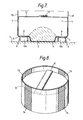
- Figure 7 is a cross-sectional view of a filled bag supported on a cradle
- Figure 8 is a perspective view of a filled bag supported on a cradle, wherein reference numerals 1-11 have the same meaning as in relation to Figures 1 and 2.
- the sleeve extension 13 is of sufficient height to permit lifting apparatus to be engaged therewith without snagging or fouling the bag and contents.
- the reinforcing sleeve 4 is formed of material having bands 14 of reinforcing threads running in the warp direction, that is not in the hoop direction. In use lifting apparatus may be engaged with those portions of the sleeve extension 13 that consist of reinforcing threads.
Landscapes
- Engineering & Computer Science (AREA)
- Mechanical Engineering (AREA)
- Bag Frames (AREA)
- Packages (AREA)
- Pallets (AREA)
Applications Claiming Priority (2)
| Application Number | Priority Date | Filing Date | Title |
|---|---|---|---|
| GB8427337 | 1984-10-29 | ||
| GB848427337A GB8427337D0 (en) | 1984-10-29 | 1984-10-29 | Intermediate bulk containers |
Publications (2)
| Publication Number | Publication Date |
|---|---|
| EP0180379A2 true EP0180379A2 (de) | 1986-05-07 |
| EP0180379A3 EP0180379A3 (de) | 1987-04-01 |
Family
ID=10568925
Family Applications (1)
| Application Number | Title | Priority Date | Filing Date |
|---|---|---|---|
| EP85307470A Withdrawn EP0180379A3 (de) | 1984-10-29 | 1985-10-16 | Intermediäre Behälter für Schüttgut |
Country Status (6)
| Country | Link |
|---|---|
| EP (1) | EP0180379A3 (de) |
| JP (1) | JPS61115846A (de) |
| AU (1) | AU4898585A (de) |
| DK (1) | DK492685A (de) |
| GB (1) | GB8427337D0 (de) |
| NO (1) | NO854293L (de) |
Cited By (7)
| Publication number | Priority date | Publication date | Assignee | Title |
|---|---|---|---|---|
| WO1993017911A1 (en) * | 1992-03-10 | 1993-09-16 | Oy W. Rosenlew Ab | Method for packaging of bulk goods into a unit-load package and a unit-load package for bulk goods |
| US6012266A (en) * | 1992-03-10 | 2000-01-11 | Upm-Kymmene Oy | Method for packing bulk goods and a container for bulk goods |
| US6205750B1 (en) | 1992-03-10 | 2001-03-27 | Upm-Kymmene Oy | Method for packaging bulk goods and a container for bulk goods |
| EP1298075A1 (de) * | 2001-10-01 | 2003-04-02 | EUREA VERPACKUNGS GMBH & CO. KG. | Verfahren zum Herstellen eines flexiblen Schüttgutbehälters und danach hergestellte Schüttgutbehälter |
| WO2003029109A3 (de) * | 2001-09-29 | 2003-09-12 | Eurea Verpackung | Verfahren zum herstellen eines flexiblen schüttgutbehälters und danach hergestellte schüttgutbehälter |
| CN103538770A (zh) * | 2012-07-09 | 2014-01-29 | 奇美实业股份有限公司 | 栈板装置以及运用栈板装置的运输方法 |
| US20160075461A1 (en) * | 2013-05-02 | 2016-03-17 | Purac Biochem Bv | Method for storage and/or transport of lactide particles |
Family Cites Families (2)
| Publication number | Priority date | Publication date | Assignee | Title |
|---|---|---|---|---|
| DE2607065A1 (de) * | 1976-02-21 | 1977-08-25 | Spohn Kg | Sackartiger grossbehaelter fuer den transport und die lagerung insbesondere von schuettguetern |
| DE3270482D1 (en) * | 1981-11-26 | 1986-05-15 | Ici Plc | Intermediate bulk containers |
-
1984
- 1984-10-29 GB GB848427337A patent/GB8427337D0/en active Pending
-
1985
- 1985-10-16 EP EP85307470A patent/EP0180379A3/de not_active Withdrawn
- 1985-10-23 AU AU48985/85A patent/AU4898585A/en not_active Abandoned
- 1985-10-25 DK DK492685A patent/DK492685A/da not_active Application Discontinuation
- 1985-10-28 NO NO854293A patent/NO854293L/no unknown
- 1985-10-29 JP JP60242561A patent/JPS61115846A/ja active Pending
Cited By (10)
| Publication number | Priority date | Publication date | Assignee | Title |
|---|---|---|---|---|
| WO1993017911A1 (en) * | 1992-03-10 | 1993-09-16 | Oy W. Rosenlew Ab | Method for packaging of bulk goods into a unit-load package and a unit-load package for bulk goods |
| US5544472A (en) * | 1992-03-10 | 1996-08-13 | Oy W. Rosenlew Ab | Method for packaging of bulk goods into a unit-load package and a unit-load package for bulk goods |
| RU2115598C1 (ru) * | 1992-03-10 | 1998-07-20 | Ой В. Росенлев АБ | Способ упаковки сыпучих материалов в штучную упаковку и штучная упаковка для сыпучих материалов |
| US6012266A (en) * | 1992-03-10 | 2000-01-11 | Upm-Kymmene Oy | Method for packing bulk goods and a container for bulk goods |
| US6205750B1 (en) | 1992-03-10 | 2001-03-27 | Upm-Kymmene Oy | Method for packaging bulk goods and a container for bulk goods |
| WO2003029109A3 (de) * | 2001-09-29 | 2003-09-12 | Eurea Verpackung | Verfahren zum herstellen eines flexiblen schüttgutbehälters und danach hergestellte schüttgutbehälter |
| EP1298075A1 (de) * | 2001-10-01 | 2003-04-02 | EUREA VERPACKUNGS GMBH & CO. KG. | Verfahren zum Herstellen eines flexiblen Schüttgutbehälters und danach hergestellte Schüttgutbehälter |
| CN103538770A (zh) * | 2012-07-09 | 2014-01-29 | 奇美实业股份有限公司 | 栈板装置以及运用栈板装置的运输方法 |
| US20160075461A1 (en) * | 2013-05-02 | 2016-03-17 | Purac Biochem Bv | Method for storage and/or transport of lactide particles |
| US10266296B2 (en) * | 2013-05-02 | 2019-04-23 | Purac Biochem Bv | Method for storage and/or transport of lactide particles |
Also Published As
| Publication number | Publication date |
|---|---|
| DK492685D0 (da) | 1985-10-25 |
| JPS61115846A (ja) | 1986-06-03 |
| DK492685A (da) | 1986-04-30 |
| GB8427337D0 (en) | 1984-12-05 |
| EP0180379A3 (de) | 1987-04-01 |
| NO854293L (no) | 1986-04-30 |
| AU4898585A (en) | 1986-05-08 |
Similar Documents
| Publication | Publication Date | Title |
|---|---|---|
| CA1146485A (en) | Self-raising strap loop | |
| US4224970A (en) | Collapsible receptacle for flowable materials | |
| US4759473A (en) | Collapsible receptacle with integral sling | |
| US4143796A (en) | Collapsible receptacle for flowable materials | |
| EP0080839B1 (de) | Behälter für Schüttgüter | |
| US4194652A (en) | Collapsible receptacle for flowable materials | |
| CA1097231A (en) | Containers | |
| KR100188806B1 (ko) | 벌크 화물 운반용 포대 | |
| US4499599A (en) | Stackable flexible bulk container | |
| US6921201B2 (en) | Bulk bag for meat and meat products | |
| US4781475A (en) | Reinforced bulk bag | |
| US8365912B2 (en) | Wire containment structure including container and bag | |
| MXPA97000876A (es) | Contenedor flexible de material a granel, con vigas laterales de soporte | |
| US20100322538A1 (en) | Flexible bulk containers constructed to be liftable from below by a forklift | |
| US5477965A (en) | Packaging element for stacked printed products | |
| EP0735974B1 (de) | Behälter | |
| US20010027826A1 (en) | Flexible intermediate bulk container with fork lift guide | |
| EP0180379A2 (de) | Intermediäre Behälter für Schüttgut | |
| CA1158574A (en) | Collapsible receptacle with integral sling | |
| WO2008039507A9 (en) | Vertical support and single-wrap collapsible container | |
| EP0265103B1 (de) | Mittelgrosse Schüttgutcontainer | |
| GB2081213A (en) | Flexible bulk container | |
| GB1590943A (en) | Containers | |
| EP0300539A1 (de) | Doppelwandiger Grosssack | |
| EP0603963A2 (de) | Beutel-Container |
Legal Events
| Date | Code | Title | Description |
|---|---|---|---|
| PUAI | Public reference made under article 153(3) epc to a published international application that has entered the european phase |
Free format text: ORIGINAL CODE: 0009012 |
|
| AK | Designated contracting states |
Kind code of ref document: A2 Designated state(s): AT BE CH DE FR GB IT LI LU NL SE |
|
| PUAL | Search report despatched |
Free format text: ORIGINAL CODE: 0009013 |
|
| AK | Designated contracting states |
Kind code of ref document: A3 Designated state(s): AT BE CH DE FR GB IT LI LU NL SE |
|
| 17P | Request for examination filed |
Effective date: 19870907 |
|
| 17Q | First examination report despatched |
Effective date: 19880422 |
|
| STAA | Information on the status of an ep patent application or granted ep patent |
Free format text: STATUS: THE APPLICATION HAS BEEN WITHDRAWN |
|
| 18W | Application withdrawn |
Withdrawal date: 19881209 |
|
| RIN1 | Information on inventor provided before grant (corrected) |
Inventor name: FORD, ANDREW GEORGE Inventor name: DIJKSMAN, ALAN MARTIEN |