EP0180410A2 - Dispositif de contrôle de la qualité d'un liquide - Google Patents
Dispositif de contrôle de la qualité d'un liquide Download PDFInfo
- Publication number
- EP0180410A2 EP0180410A2 EP85307663A EP85307663A EP0180410A2 EP 0180410 A2 EP0180410 A2 EP 0180410A2 EP 85307663 A EP85307663 A EP 85307663A EP 85307663 A EP85307663 A EP 85307663A EP 0180410 A2 EP0180410 A2 EP 0180410A2
- Authority
- EP
- European Patent Office
- Prior art keywords
- cell
- liquid
- monitor
- detector
- quality monitor
- Prior art date
- Legal status (The legal status is an assumption and is not a legal conclusion. Google has not performed a legal analysis and makes no representation as to the accuracy of the status listed.)
- Granted
Links
Images

Classifications
-
- G—PHYSICS
- G01—MEASURING; TESTING
- G01N—INVESTIGATING OR ANALYSING MATERIALS BY DETERMINING THEIR CHEMICAL OR PHYSICAL PROPERTIES
- G01N21/00—Investigating or analysing materials by the use of optical means, i.e. using sub-millimetre waves, infrared, visible or ultraviolet light
- G01N21/17—Systems in which incident light is modified in accordance with the properties of the material investigated
- G01N21/47—Scattering, i.e. diffuse reflection
- G01N21/49—Scattering, i.e. diffuse reflection within a body or fluid
- G01N21/53—Scattering, i.e. diffuse reflection within a body or fluid within a flowing fluid, e.g. smoke
-
- G—PHYSICS
- G01—MEASURING; TESTING
- G01N—INVESTIGATING OR ANALYSING MATERIALS BY DETERMINING THEIR CHEMICAL OR PHYSICAL PROPERTIES
- G01N21/00—Investigating or analysing materials by the use of optical means, i.e. using sub-millimetre waves, infrared, visible or ultraviolet light
- G01N21/01—Arrangements or apparatus for facilitating the optical investigation
- G01N21/03—Cuvette constructions
- G01N21/0332—Cuvette constructions with temperature control
-
- G—PHYSICS
- G01—MEASURING; TESTING
- G01N—INVESTIGATING OR ANALYSING MATERIALS BY DETERMINING THEIR CHEMICAL OR PHYSICAL PROPERTIES
- G01N21/00—Investigating or analysing materials by the use of optical means, i.e. using sub-millimetre waves, infrared, visible or ultraviolet light
- G01N21/01—Arrangements or apparatus for facilitating the optical investigation
- G01N21/15—Preventing contamination of the components of the optical system or obstruction of the light path
-
- G—PHYSICS
- G01—MEASURING; TESTING
- G01N—INVESTIGATING OR ANALYSING MATERIALS BY DETERMINING THEIR CHEMICAL OR PHYSICAL PROPERTIES
- G01N21/00—Investigating or analysing materials by the use of optical means, i.e. using sub-millimetre waves, infrared, visible or ultraviolet light
- G01N21/17—Systems in which incident light is modified in accordance with the properties of the material investigated
- G01N21/47—Scattering, i.e. diffuse reflection
- G01N21/49—Scattering, i.e. diffuse reflection within a body or fluid
- G01N21/53—Scattering, i.e. diffuse reflection within a body or fluid within a flowing fluid, e.g. smoke
- G01N21/532—Scattering, i.e. diffuse reflection within a body or fluid within a flowing fluid, e.g. smoke with measurement of scattering and transmission
-
- G—PHYSICS
- G01—MEASURING; TESTING
- G01N—INVESTIGATING OR ANALYSING MATERIALS BY DETERMINING THEIR CHEMICAL OR PHYSICAL PROPERTIES
- G01N2201/00—Features of devices classified in G01N21/00
- G01N2201/06—Illumination; Optics
- G01N2201/062—LED's
-
- G—PHYSICS
- G01—MEASURING; TESTING
- G01N—INVESTIGATING OR ANALYSING MATERIALS BY DETERMINING THEIR CHEMICAL OR PHYSICAL PROPERTIES
- G01N2201/00—Features of devices classified in G01N21/00
- G01N2201/12—Circuits of general importance; Signal processing
- G01N2201/126—Microprocessor processing
-
- G—PHYSICS
- G01—MEASURING; TESTING
- G01N—INVESTIGATING OR ANALYSING MATERIALS BY DETERMINING THEIR CHEMICAL OR PHYSICAL PROPERTIES
- G01N2201/00—Features of devices classified in G01N21/00
- G01N2201/12—Circuits of general importance; Signal processing
- G01N2201/128—Alternating sample and standard or reference part in one path
Definitions
- This invention relates to liquid quality monitors and in particular to monitors for boiler condensate water of a power station.
- a major source of oil in boiler feed water is turbine lubricating oil from sealing glands. On 500 MW fossil fired units an oil level of 0.50 pm is the maximum acceptable. High oil levels incur cost penalties by contamination of condensate polishing plant, feed-heaters and are also suspected of increasing the risk of boiler tube failure.
- a liquid quality monitor of the kind comprising a cell through which the liquid to be monitored can be caused to flow, a light source coupled to one side of the cell, one or more detectors, arranged at respective angles to a light beam output from the light source and directed across the cell, to detect light scattered from contamination in the liquid to be monitored when it is caused to flow in the cell and producing corresponding detector output or outputs, respectively, characterised by the provision of means for enabling the cell to be flushed with a clean liquid, the detector output or outputs then corresponding to the background scattered light level and comprising offset voltage or voltages, respectively, means for compensating the offset voltage or voltages for difference in temperature between the liquid to be monitored and the clean liquid and processor means for calculating the contaminant level from the first mentioned detector output or outputs and the compensated offset voltage or voltages.
- the monitor of the present invention employs a multi-angle scatter cell which may be as illustrated schematically in Figures 1 and 2.
- the monitor employs the scattering of pulsed near infra-red radiation, for example 900 nm, from a narrow beam LED by the oil drops in suspension.
- pulsed near infra-red radiation for example 900 nm
- other light sources may be employed, for example semiconductor lasers, and/or fibre optics.
- the forward scattered light from an LED 1 is detected at various cell angles by photodiodes 2, each directly connected to a respective AC pre-amplifier 3 only one of which is indicated in Figure 2.
- the preamplifiers 3 and photodiodes 2 are mounted on the cell 4 in a housing 5.
- Each preamplifier has a potentiometer which allows each channel gain to be adjusted during calibration.
- the pre-amplified photodiode signals are amplified, digitised and processed to give an oil content reading. Contributions due to particulates in the water, such as rust, may be removed or alternatively the signals may be processed for particulate content readings.
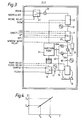
- each preamplifier stage 3 Associated with each preamplifier stage 3 is a respective main amplifier stage 6 only one of which is shown comprising an amplifier 7 providing AC gain, a phase sensitive detector 8, and an amplifier 9 providing DC gain with a variable DC offset 10.
- the outputs are applied to processing means such as a microprocessor (not shown). Even with clean water in the cell some light scatter occurs from the walls and windows. This gives rise to an offset value which is adjusted out at 10 in the D.C. amplifier stages.
- a baffle 11 extends across the cell to prevent any light directly illuminating the photodiodes 2. The light transmitted directly across the cell is measured by a direct detector (photodiode) 12 and used in an automatic gain control circuit to maintain the drive for the LED 1 and thus maintain the illumination constant.
- the cell 4 is incorporated in the overall monitor as indicated in the plumbing layout of Figure 3.
- the monitor is in use coupled to two water supplies, one being the water to be monitored, which is coupled to the sample inlet, and the other being a clean mains supply, which is coupled to the flush inlet.
- the mains supply is used to flush out the monitor and provide a calibration supply.
- the supply is selected by an inlet solenoid valve 13 which, for example, selects the flush supply when energised.
- the supply is coupled to the cell 4 via a line 14 including a pump 15 and a "sample input" valve 16.
- the pump inlet pressure P i and outlet pressure P D are monitored at 17 and 18.
- the cell output pressure P 0 is monitored at 19.
- Valves 20a and 20b together with valve 16 allow the sample supply to be directed past an injection point where a calibrated dose of particulates, or oil, can be injected into the stream by an injection pump 21 which is such that a constant concentration of injectant is maintained independently of the bulk flow rate of the stream.
- the injection point can also be switched to just before the pump as indicated by line 22.
- a turbine flowmeter 23 is disposed after the cell 4 and a control signal developed from the flowmeter output fed back to the injection pump for control thereof.
- a window-wash system including a window wash solenoid valve 24 is incorporated in the monitor.
- An orifice plate is inserted in the line to the cell at 25, that is after the line to the window-wash system. This gives a pressure drop between the water in the window-wash line and the sample stream so that, when the window wash solenoid valve is open, a stream of sample water at a higher velocity than the bulk flow is directed over the optical windows to maintain cleanliness.
- a drain valve 26 is partially closed in normal operation to apply a back-pressure to the system, preventing cavitation and forcing any entrained air into solution. Air bubbles will give erroneous readings since light is scattered by them.
- An output solenoid valve 27 determines where the sample stream is routed, either to a drain or recirculated in the boiler condensate system or otherwise from which it is sampled. In order to prevent calibration particules being discharged into the boiler condensate system the software may be configured so that the valve 27 selects DRAIN when the input solenoid valve 13 selects FLUSH and selects RECIRCULATE when the input valve selects SAMPLE.
- the valves 16, 19, 20 and 26 are manually operated valves.
- the pump 15 may be a centrifugal pump and serves to provide a head for the window-wash pressure, a higher flow rate during flushes and some degree of emulsification for larger oil droplets.
- the software may be configured so that the pump is only on during "flush", "window-wash” or when the scattered light level exceeds a pre-set threshold. This latter feature may energise the pump any time in the sampling process and is included to provide emulsification of any large oil droplets that might be present. Provided there is sufficient head to drive the sample through the monitor the pump need not be on.
- the pump is energised to provide further emulsification of the sample, increasing the signal levels in accord with the calibration. This feature increases pump lifetime and lowers sample throughput for those installations where the sample is discarded rather than restored to the recirculating system.
- the monitor further includes a temperature sensor mounted close to the photodiodes which allows the offset voltages (scattered light levels with clean water or background scattered light levels) to be compensated for temperature variations.
- a temperature sensor mounted close to the photodiodes which allows the offset voltages (scattered light levels with clean water or background scattered light levels) to be compensated for temperature variations.
- the temperature of the flush supply clean water
- supply errors can arise in the computed levels of oil or particulate contamination.
- a software algorithm for such temperature compensation will be described hereinafter. This algorithm is such that any gain changes made during routine calibration do not necessitate change to the algorithm, which is thus independent of the pre-amplifier.
- This allows a factory calibration of the temperature dependence of the offset which does not need to be subsequently changed.
- the temperature dependence may arise from the LED, the photodetectors, or geometrical size changes of the cell itself.
- Both K and S can be determined in a factory calibration, and entered into the monitor microprocessor.
- the offset Z 1 at T 1 can be measured.
- the offset Z 2 can be calculated from the above expression (1).
- the monitor operates automatically such that with a control switch turned to "sample” it goes through a predetermined cycle which is repeated until the monitor is turned off.
- Any manual interruption to this cycle such as a "flush”, “window-wash” or operation of a "test” switch causes the cycle to be extended for the length of the manual interruption.
- a one hour operating cycle may comprise a four minute flush with the clean flush water; a twenty second window wash; initial system checks (described in greater detail hereinafter); offset measurement; sampling routine, comprising continually monitoring the oil level. After thirty minutes the sampling routine may be interrupted by a twenty second window-wash.
- One hour after turn on the cycle recommences with a four minute flush.
- the initial flush sequence is long enough for the cell to reach temperature equilibrium with the water.
- the offset voltages are measured and stored together with the temperature at which they are measured.
- the sample water supply is automatically selected and the scatter voltages measured.
- the temperature of the sample water is measured to allow the offset voltages, which are subtracted from the sample voltages, to be compensated for any temperature change.
- the scatter voltages may be smoothed with a digital filter to reduce noise, the filter time constant being approximately one minute.
- the scatter signals are then input to the algorithm for calculating the oil concentration and particulate concentration therefrom. If the calculated oil level exceeds a preset alarm level then this can be used to illuminate an "oil high" warning light or to operate an alarm at a remote location.
- the main signal processing/system control functions are controlled by the above mentioned microprocessor which is mounted on a main printed circuit board in a control box (not shown).
- a control box On a front panel of the control box are all the controls and indicators necessary for routine operation of the monitor. Inside are further switches necessary for the calibration procedure and also a number of self-diagnostic LED error indicators.
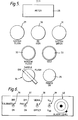
- the front panel layout is shown in Figure 5 and includes a meter 28 upon which the oil concentration can be displayed, a system flush lamp 29, an oil high lamp 30, a system error lamp 31, a window flush switch 32, a test switch 33, an off-sample-flush switch 34 and a power-on lamp 35.
- the oil high lamp 30 is illuminated if the meter level exceeds the level set by an internal set-alarm potentiometer.
- the alarm has in-built hysteresis of 0.1 ppm so that the oil-high alarm will be set if, say, the level exceeds 0.5 ppm but will not be cleared until the level is below 0.4 ppm. After fifteen seconds of "oil high" a delayed alarm relay will close to give a remote alarm signal.
- the lamp 30 may flash every second under certain error conditions.
- the system error lamp 31 is illuminated if the monitor is in a condition which prevents display of the true oil content. The various causes for this and the self diagnostics associated with it are described hereinafter. Lamp 31 may also flash every second under certain error conditions.
- the meter 28 displays oil concentration (0-2 ppm). In the calibration mode, however, the meter can display other values. One of the above-mentioned internal switches allows display of oil or particulate concentration.
- the system error lamp will light whenever an error that prevents the monitor from giving reliable readings occurs. Some situations will allow the monitor to continue if the fault clears, whereas others require attention from site personnel.
- the LED's may be included on the main printed circuit. These correspond to various error conditions. Preferably the seven LED's are arranged in a horizontal row and they correspond respectively, from left to right, to preamplifier error; microprocessor fail; calibration error; direct beam fail; adc fail; t fail; and no flow.
- the LED's may be off (0) on (X) or flashing (#). All seven LED's are off and the system error (SE) and oil high (OH) lamps are off when the monitor is operating normally.
- SE and OH lamps may be off (0), on (X) or flashing (#).
- Initial system checks are performed approximately five minutes and twenty seconds after the monitor is initially switched to sample, and every hour thereafter.
- the system error lamp will be illuminated and the monitor will stop its cycle.
- the direct beam level is normally maintained approximately constant by the automatic gain control circuit. This level may not be able to be maintained if the light output from the transmitter is too low (even at maximum drive current) or the direct beam window is excessively dirty.
Landscapes
- Physics & Mathematics (AREA)
- Health & Medical Sciences (AREA)
- Life Sciences & Earth Sciences (AREA)
- Chemical & Material Sciences (AREA)
- Analytical Chemistry (AREA)
- Biochemistry (AREA)
- General Health & Medical Sciences (AREA)
- General Physics & Mathematics (AREA)
- Immunology (AREA)
- Pathology (AREA)
- Investigating Or Analysing Materials By Optical Means (AREA)
- Sampling And Sample Adjustment (AREA)
- Examining Or Testing Airtightness (AREA)
Priority Applications (1)
| Application Number | Priority Date | Filing Date | Title |
|---|---|---|---|
| AT85307663T ATE72901T1 (de) | 1984-10-26 | 1985-10-24 | Vorrichtung zur gueteueberwachung einer fluessigkeit. |
Applications Claiming Priority (2)
| Application Number | Priority Date | Filing Date | Title |
|---|---|---|---|
| GB08427177A GB2166233B (en) | 1984-10-26 | 1984-10-26 | Liquid quality monitor |
| GB8427177 | 1984-10-26 |
Publications (3)
| Publication Number | Publication Date |
|---|---|
| EP0180410A2 true EP0180410A2 (fr) | 1986-05-07 |
| EP0180410A3 EP0180410A3 (en) | 1989-01-11 |
| EP0180410B1 EP0180410B1 (fr) | 1992-02-26 |
Family
ID=10568827
Family Applications (1)
| Application Number | Title | Priority Date | Filing Date |
|---|---|---|---|
| EP85307663A Expired - Lifetime EP0180410B1 (fr) | 1984-10-26 | 1985-10-24 | Dispositif de contrôle de la qualité d'un liquide |
Country Status (7)
| Country | Link |
|---|---|
| US (1) | US4672216A (fr) |
| EP (1) | EP0180410B1 (fr) |
| JP (1) | JPS61107141A (fr) |
| AT (1) | ATE72901T1 (fr) |
| AU (1) | AU582588B2 (fr) |
| DE (1) | DE3585425D1 (fr) |
| GB (1) | GB2166233B (fr) |
Cited By (1)
| Publication number | Priority date | Publication date | Assignee | Title |
|---|---|---|---|---|
| DE202014104059U1 (de) * | 2014-08-29 | 2015-12-06 | KDT Kompressoren- und Drucklufttechnik GmbH | Messvorrichtung zur Messung der Konzentration von Öl- und Kraftstoffverunreinigungen in wässriger Lösung und Druckluftanlage mit einer solchen Messvorrichtung |
Families Citing this family (17)
| Publication number | Priority date | Publication date | Assignee | Title |
|---|---|---|---|---|
| GB8523747D0 (en) * | 1985-09-26 | 1985-10-30 | Vg Instr Group | Fibre size monitor |
| JPS62127633A (ja) * | 1985-11-28 | 1987-06-09 | Suntory Ltd | 液面測定方法および装置 |
| GB2304188B (en) * | 1992-11-05 | 1997-05-07 | Apv Uk Plc | Solid particle detector |
| US5919707A (en) * | 1994-12-22 | 1999-07-06 | Nalco Chemical Company | Monitoring of rolling oil emulsions |
| GB2299161A (en) * | 1995-03-24 | 1996-09-25 | Alan Philip Roper | Electronic digital control unit for measuring pollution levels in liquids |
| US5739916A (en) * | 1995-12-04 | 1998-04-14 | University Of Alabama At Huntsville | Apparatus and method for determining the concentration of species in a substance |
| JP2002202254A (ja) * | 2000-10-30 | 2002-07-19 | Dkk Toa Corp | 光測定方法及び装置 |
| US20040016686A1 (en) * | 2002-07-24 | 2004-01-29 | Wyatt Philip J. | Absolute measurement centrifuge |
| US7294513B2 (en) * | 2002-07-24 | 2007-11-13 | Wyatt Technology Corporation | Method and apparatus for characterizing solutions of small particles |
| RU2308707C2 (ru) * | 2005-08-04 | 2007-10-20 | Государственное образовательное учреждение Высшего профессионального образования Казанский государственный технический университет им.А.Н.Туполева | Детектор концентрации нефти в воде |
| TW200742847A (en) * | 2006-05-15 | 2007-11-16 | Syspotek Corp | Refractive fuel-concentration detecto |
| US20090185188A1 (en) * | 2008-01-22 | 2009-07-23 | Cummins Filtration Ip, Inc. | Pass-fail tool for testing particulate contamination level in a fluid |
| EP3037803A1 (fr) * | 2014-12-22 | 2016-06-29 | Grundfos Holding A/S | Dispositif d'analyse par radioscopie d'un liquide |
| EP3037804A1 (fr) * | 2014-12-22 | 2016-06-29 | Grundfos Holding A/S | Procédé de détection quantitative et qualitative de particules dans un liquide |
| US20180312419A1 (en) * | 2017-04-27 | 2018-11-01 | Aquafresco, Inc. | Water reuse systems and related methods and apparatuses |
| US11906426B2 (en) * | 2018-06-29 | 2024-02-20 | Hach Company | Suspended solids measurement of wastewater |
| DE102020128684A1 (de) * | 2020-10-30 | 2022-05-05 | Heinzmann Gmbh & Co. Kg | Ölnebeldetektor zur Detektion und/oder Analyse von Öl-Luftgemischen mit einer optischen Messanordnung sowie zugehörige Verfahren |
Family Cites Families (11)
| Publication number | Priority date | Publication date | Assignee | Title |
|---|---|---|---|---|
| GB1180480A (en) * | 1967-05-03 | 1970-02-04 | Bowser Inc | Improved Method of and Apparatus for Monitoring Contamination in Liquids |
| US3576558A (en) * | 1968-05-14 | 1971-04-27 | Univ Utah | Opacity comparison apparatus and method |
| GB1281342A (en) * | 1968-10-09 | 1972-07-12 | English Clays Lovering Pochin | Apparatus for measuring concentration of solids in a fluid |
| US3770351A (en) * | 1971-11-23 | 1973-11-06 | Science Spectrum | Optical analyzer for microparticles |
| GB1556029A (en) * | 1976-10-29 | 1979-11-14 | Standard Telephones Cables Ltd | Oil in water detection |
| GB1602969A (en) * | 1977-08-26 | 1981-11-18 | Standard Telephones Cables Ltd | Oil-in-water detection system |
| US4153837A (en) * | 1978-02-16 | 1979-05-08 | Anarad, Inc. | Optical gas analyzer |
| GB1588862A (en) * | 1978-05-11 | 1981-04-29 | Standard Telephones Cables Ltd | Measuring oil in water |
| US4265536A (en) * | 1979-06-25 | 1981-05-05 | Waters Associates, Inc. | Electrical zeroing of light beam |
| US4221485A (en) * | 1979-06-04 | 1980-09-09 | Honeywell Inc. | Optical smoke detector |
| JPS57199943A (en) * | 1981-06-03 | 1982-12-08 | Hitachi Ltd | Measuring device for wetness of steam |
-
1984
- 1984-10-26 GB GB08427177A patent/GB2166233B/en not_active Expired
-
1985
- 1985-10-11 AU AU48518/85A patent/AU582588B2/en not_active Ceased
- 1985-10-22 US US06/789,989 patent/US4672216A/en not_active Expired - Lifetime
- 1985-10-24 DE DE8585307663T patent/DE3585425D1/de not_active Expired - Lifetime
- 1985-10-24 EP EP85307663A patent/EP0180410B1/fr not_active Expired - Lifetime
- 1985-10-24 AT AT85307663T patent/ATE72901T1/de not_active IP Right Cessation
- 1985-10-25 JP JP60237806A patent/JPS61107141A/ja active Granted
Cited By (1)
| Publication number | Priority date | Publication date | Assignee | Title |
|---|---|---|---|---|
| DE202014104059U1 (de) * | 2014-08-29 | 2015-12-06 | KDT Kompressoren- und Drucklufttechnik GmbH | Messvorrichtung zur Messung der Konzentration von Öl- und Kraftstoffverunreinigungen in wässriger Lösung und Druckluftanlage mit einer solchen Messvorrichtung |
Also Published As
| Publication number | Publication date |
|---|---|
| GB2166233A (en) | 1986-04-30 |
| EP0180410A3 (en) | 1989-01-11 |
| DE3585425D1 (de) | 1992-04-02 |
| AU4851885A (en) | 1986-05-01 |
| US4672216A (en) | 1987-06-09 |
| AU582588B2 (en) | 1989-04-06 |
| GB2166233B (en) | 1988-06-02 |
| JPS61107141A (ja) | 1986-05-26 |
| EP0180410B1 (fr) | 1992-02-26 |
| ATE72901T1 (de) | 1992-03-15 |
| JPH0458900B2 (fr) | 1992-09-18 |
| GB8427177D0 (en) | 1984-12-05 |
Similar Documents
| Publication | Publication Date | Title |
|---|---|---|
| EP0180410B1 (fr) | Dispositif de contrôle de la qualité d'un liquide | |
| US5125747A (en) | Optical analytical instrument and method having improved calibration | |
| US4017190A (en) | Blood leak detector comparing intensities of high absorption band and low absorption band of a single beam of light passing through a sample | |
| US5477218A (en) | Smoke detecting apparatus capable of detecting both smoke fine particles | |
| US6396405B1 (en) | Automatic verification of smoke detector operation within calibration limits | |
| US6331704B1 (en) | Hydraulic fluid contamination monitor | |
| US20090310123A1 (en) | Blood concentrate detector | |
| CA1075035A (fr) | Detection d'huile dans l'eau | |
| EP1685400B1 (fr) | Appareil et procede de controle d'un liquide | |
| JPH0311772B2 (fr) | ||
| EP2366100A1 (fr) | Dispositif de capteur de turbidité néphélométrique | |
| US5777748A (en) | Device for determining density and concentration of visible constituents in fluids | |
| GB1560422A (en) | Blood leak detector | |
| KR20060127885A (ko) | 산란광 신호를 측정하기 위한 방법 및 상기 방법을구현하는 산란광 검출기 | |
| US5422720A (en) | Blood culture sensor station utilizing two distinct light sources | |
| JPH07151680A (ja) | 微粒子検出兼用煙検出装置 | |
| US6476911B1 (en) | Backscatter instrument for monitoring particulate levels in a gas stream | |
| US9182344B1 (en) | Device for the detector of fouling on optical surfaces of a nephelometric turbidimeter submerged in a liquid | |
| CN111693543B (zh) | 具有自检功能的监测设备的监测方法 | |
| JP3995615B2 (ja) | 分光式濃度測定装置及びその光源安定判別方法 | |
| JP2000146833A (ja) | 連続式有機汚濁モニタにおける検水流路の異常検知方法 | |
| JPS5946540A (ja) | 濁度計 | |
| JPS6033391Y2 (ja) | 油分濃度計のワイパ装置 | |
| JPH05133959A (ja) | 警報発信機能付自動連続分析装置 | |
| CN220207449U (zh) | 一种基于流动注射的光学法检测pH值的装置 |
Legal Events
| Date | Code | Title | Description |
|---|---|---|---|
| PUAI | Public reference made under article 153(3) epc to a published international application that has entered the european phase |
Free format text: ORIGINAL CODE: 0009012 |
|
| AK | Designated contracting states |
Kind code of ref document: A2 Designated state(s): AT BE CH DE FR IT LI LU NL SE |
|
| PUAL | Search report despatched |
Free format text: ORIGINAL CODE: 0009013 |
|
| AK | Designated contracting states |
Kind code of ref document: A3 Designated state(s): AT BE CH DE FR IT LI LU NL SE |
|
| 17P | Request for examination filed |
Effective date: 19890619 |
|
| 17Q | First examination report despatched |
Effective date: 19900918 |
|
| RAP1 | Party data changed (applicant data changed or rights of an application transferred) |
Owner name: VAF INSTRUMENTS |
|
| GRAA | (expected) grant |
Free format text: ORIGINAL CODE: 0009210 |
|
| AK | Designated contracting states |
Kind code of ref document: B1 Designated state(s): AT BE CH DE FR IT LI LU NL SE |
|
| REF | Corresponds to: |
Ref document number: 72901 Country of ref document: AT Date of ref document: 19920315 Kind code of ref document: T |
|
| REF | Corresponds to: |
Ref document number: 3585425 Country of ref document: DE Date of ref document: 19920402 |
|
| ET | Fr: translation filed | ||
| ITF | It: translation for a ep patent filed | ||
| PLBE | No opposition filed within time limit |
Free format text: ORIGINAL CODE: 0009261 |
|
| STAA | Information on the status of an ep patent application or granted ep patent |
Free format text: STATUS: NO OPPOSITION FILED WITHIN TIME LIMIT |
|
| 26N | No opposition filed | ||
| EPTA | Lu: last paid annual fee | ||
| EAL | Se: european patent in force in sweden |
Ref document number: 85307663.6 |
|
| PGFP | Annual fee paid to national office [announced via postgrant information from national office to epo] |
Ref country code: SE Payment date: 20021004 Year of fee payment: 18 |
|
| PGFP | Annual fee paid to national office [announced via postgrant information from national office to epo] |
Ref country code: FR Payment date: 20021008 Year of fee payment: 18 |
|
| PGFP | Annual fee paid to national office [announced via postgrant information from national office to epo] |
Ref country code: AT Payment date: 20021011 Year of fee payment: 18 |
|
| PGFP | Annual fee paid to national office [announced via postgrant information from national office to epo] |
Ref country code: DE Payment date: 20021024 Year of fee payment: 18 |
|
| PGFP | Annual fee paid to national office [announced via postgrant information from national office to epo] |
Ref country code: LU Payment date: 20021029 Year of fee payment: 18 |
|
| PGFP | Annual fee paid to national office [announced via postgrant information from national office to epo] |
Ref country code: CH Payment date: 20021101 Year of fee payment: 18 |
|
| PGFP | Annual fee paid to national office [announced via postgrant information from national office to epo] |
Ref country code: BE Payment date: 20021219 Year of fee payment: 18 |
|
| PGFP | Annual fee paid to national office [announced via postgrant information from national office to epo] |
Ref country code: NL Payment date: 20030829 Year of fee payment: 19 |
|
| PG25 | Lapsed in a contracting state [announced via postgrant information from national office to epo] |
Ref country code: LU Free format text: LAPSE BECAUSE OF NON-PAYMENT OF DUE FEES Effective date: 20031024 Ref country code: AT Free format text: LAPSE BECAUSE OF NON-PAYMENT OF DUE FEES Effective date: 20031024 |
|
| PG25 | Lapsed in a contracting state [announced via postgrant information from national office to epo] |
Ref country code: SE Free format text: LAPSE BECAUSE OF NON-PAYMENT OF DUE FEES Effective date: 20031025 |
|
| PG25 | Lapsed in a contracting state [announced via postgrant information from national office to epo] |
Ref country code: LI Free format text: LAPSE BECAUSE OF NON-PAYMENT OF DUE FEES Effective date: 20031031 Ref country code: CH Free format text: LAPSE BECAUSE OF NON-PAYMENT OF DUE FEES Effective date: 20031031 Ref country code: BE Free format text: LAPSE BECAUSE OF NON-PAYMENT OF DUE FEES Effective date: 20031031 |
|
| BERE | Be: lapsed |
Owner name: *VAF INSTRUMENTS Effective date: 20031031 |
|
| PG25 | Lapsed in a contracting state [announced via postgrant information from national office to epo] |
Ref country code: DE Free format text: LAPSE BECAUSE OF NON-PAYMENT OF DUE FEES Effective date: 20040501 |
|
| EUG | Se: european patent has lapsed | ||
| REG | Reference to a national code |
Ref country code: CH Ref legal event code: PL |
|
| PG25 | Lapsed in a contracting state [announced via postgrant information from national office to epo] |
Ref country code: FR Free format text: LAPSE BECAUSE OF NON-PAYMENT OF DUE FEES Effective date: 20040630 |
|
| REG | Reference to a national code |
Ref country code: FR Ref legal event code: ST |
|
| PG25 | Lapsed in a contracting state [announced via postgrant information from national office to epo] |
Ref country code: NL Free format text: LAPSE BECAUSE OF NON-PAYMENT OF DUE FEES Effective date: 20050501 |
|
| NLV4 | Nl: lapsed or anulled due to non-payment of the annual fee |
Effective date: 20050501 |