EP0180459A2 - Magnetooptisches Speichermedium und Gerät zum Schreiben auf und Lesen von dem Medium - Google Patents
Magnetooptisches Speichermedium und Gerät zum Schreiben auf und Lesen von dem Medium Download PDFInfo
- Publication number
- EP0180459A2 EP0180459A2 EP85307828A EP85307828A EP0180459A2 EP 0180459 A2 EP0180459 A2 EP 0180459A2 EP 85307828 A EP85307828 A EP 85307828A EP 85307828 A EP85307828 A EP 85307828A EP 0180459 A2 EP0180459 A2 EP 0180459A2
- Authority
- EP
- European Patent Office
- Prior art keywords
- magneto
- optical
- memory medium
- storage layers
- storage
- Prior art date
- Legal status (The legal status is an assumption and is not a legal conclusion. Google has not performed a legal analysis and makes no representation as to the accuracy of the status listed.)
- Granted
Links
Images


Classifications
-
- G—PHYSICS
- G11—INFORMATION STORAGE
- G11B—INFORMATION STORAGE BASED ON RELATIVE MOVEMENT BETWEEN RECORD CARRIER AND TRANSDUCER
- G11B11/00—Recording on or reproducing from the same record carrier wherein for these two operations the methods are covered by different main groups of groups G11B3/00 - G11B7/00 or by different subgroups of group G11B9/00; Record carriers therefor
- G11B11/10—Recording on or reproducing from the same record carrier wherein for these two operations the methods are covered by different main groups of groups G11B3/00 - G11B7/00 or by different subgroups of group G11B9/00; Record carriers therefor using recording by magnetic means or other means for magnetisation or demagnetisation of a record carrier, e.g. light induced spin magnetisation; Demagnetisation by thermal or stress means in the presence or not of an orienting magnetic field
- G11B11/105—Recording on or reproducing from the same record carrier wherein for these two operations the methods are covered by different main groups of groups G11B3/00 - G11B7/00 or by different subgroups of group G11B9/00; Record carriers therefor using recording by magnetic means or other means for magnetisation or demagnetisation of a record carrier, e.g. light induced spin magnetisation; Demagnetisation by thermal or stress means in the presence or not of an orienting magnetic field using a beam of light or a magnetic field for recording by change of magnetisation and a beam of light for reproducing, i.e. magneto-optical, e.g. light-induced thermomagnetic recording, spin magnetisation recording, Kerr or Faraday effect reproducing
- G11B11/10502—Recording on or reproducing from the same record carrier wherein for these two operations the methods are covered by different main groups of groups G11B3/00 - G11B7/00 or by different subgroups of group G11B9/00; Record carriers therefor using recording by magnetic means or other means for magnetisation or demagnetisation of a record carrier, e.g. light induced spin magnetisation; Demagnetisation by thermal or stress means in the presence or not of an orienting magnetic field using a beam of light or a magnetic field for recording by change of magnetisation and a beam of light for reproducing, i.e. magneto-optical, e.g. light-induced thermomagnetic recording, spin magnetisation recording, Kerr or Faraday effect reproducing characterised by the transducing operation to be executed
- G11B11/10504—Recording
-
- G—PHYSICS
- G11—INFORMATION STORAGE
- G11B—INFORMATION STORAGE BASED ON RELATIVE MOVEMENT BETWEEN RECORD CARRIER AND TRANSDUCER
- G11B11/00—Recording on or reproducing from the same record carrier wherein for these two operations the methods are covered by different main groups of groups G11B3/00 - G11B7/00 or by different subgroups of group G11B9/00; Record carriers therefor
- G11B11/10—Recording on or reproducing from the same record carrier wherein for these two operations the methods are covered by different main groups of groups G11B3/00 - G11B7/00 or by different subgroups of group G11B9/00; Record carriers therefor using recording by magnetic means or other means for magnetisation or demagnetisation of a record carrier, e.g. light induced spin magnetisation; Demagnetisation by thermal or stress means in the presence or not of an orienting magnetic field
- G11B11/105—Recording on or reproducing from the same record carrier wherein for these two operations the methods are covered by different main groups of groups G11B3/00 - G11B7/00 or by different subgroups of group G11B9/00; Record carriers therefor using recording by magnetic means or other means for magnetisation or demagnetisation of a record carrier, e.g. light induced spin magnetisation; Demagnetisation by thermal or stress means in the presence or not of an orienting magnetic field using a beam of light or a magnetic field for recording by change of magnetisation and a beam of light for reproducing, i.e. magneto-optical, e.g. light-induced thermomagnetic recording, spin magnetisation recording, Kerr or Faraday effect reproducing
- G11B11/10502—Recording on or reproducing from the same record carrier wherein for these two operations the methods are covered by different main groups of groups G11B3/00 - G11B7/00 or by different subgroups of group G11B9/00; Record carriers therefor using recording by magnetic means or other means for magnetisation or demagnetisation of a record carrier, e.g. light induced spin magnetisation; Demagnetisation by thermal or stress means in the presence or not of an orienting magnetic field using a beam of light or a magnetic field for recording by change of magnetisation and a beam of light for reproducing, i.e. magneto-optical, e.g. light-induced thermomagnetic recording, spin magnetisation recording, Kerr or Faraday effect reproducing characterised by the transducing operation to be executed
- G11B11/10515—Reproducing
-
- G—PHYSICS
- G11—INFORMATION STORAGE
- G11B—INFORMATION STORAGE BASED ON RELATIVE MOVEMENT BETWEEN RECORD CARRIER AND TRANSDUCER
- G11B11/00—Recording on or reproducing from the same record carrier wherein for these two operations the methods are covered by different main groups of groups G11B3/00 - G11B7/00 or by different subgroups of group G11B9/00; Record carriers therefor
- G11B11/10—Recording on or reproducing from the same record carrier wherein for these two operations the methods are covered by different main groups of groups G11B3/00 - G11B7/00 or by different subgroups of group G11B9/00; Record carriers therefor using recording by magnetic means or other means for magnetisation or demagnetisation of a record carrier, e.g. light induced spin magnetisation; Demagnetisation by thermal or stress means in the presence or not of an orienting magnetic field
- G11B11/105—Recording on or reproducing from the same record carrier wherein for these two operations the methods are covered by different main groups of groups G11B3/00 - G11B7/00 or by different subgroups of group G11B9/00; Record carriers therefor using recording by magnetic means or other means for magnetisation or demagnetisation of a record carrier, e.g. light induced spin magnetisation; Demagnetisation by thermal or stress means in the presence or not of an orienting magnetic field using a beam of light or a magnetic field for recording by change of magnetisation and a beam of light for reproducing, i.e. magneto-optical, e.g. light-induced thermomagnetic recording, spin magnetisation recording, Kerr or Faraday effect reproducing
- G11B11/10532—Heads
-
- G—PHYSICS
- G11—INFORMATION STORAGE
- G11B—INFORMATION STORAGE BASED ON RELATIVE MOVEMENT BETWEEN RECORD CARRIER AND TRANSDUCER
- G11B11/00—Recording on or reproducing from the same record carrier wherein for these two operations the methods are covered by different main groups of groups G11B3/00 - G11B7/00 or by different subgroups of group G11B9/00; Record carriers therefor
- G11B11/10—Recording on or reproducing from the same record carrier wherein for these two operations the methods are covered by different main groups of groups G11B3/00 - G11B7/00 or by different subgroups of group G11B9/00; Record carriers therefor using recording by magnetic means or other means for magnetisation or demagnetisation of a record carrier, e.g. light induced spin magnetisation; Demagnetisation by thermal or stress means in the presence or not of an orienting magnetic field
- G11B11/105—Recording on or reproducing from the same record carrier wherein for these two operations the methods are covered by different main groups of groups G11B3/00 - G11B7/00 or by different subgroups of group G11B9/00; Record carriers therefor using recording by magnetic means or other means for magnetisation or demagnetisation of a record carrier, e.g. light induced spin magnetisation; Demagnetisation by thermal or stress means in the presence or not of an orienting magnetic field using a beam of light or a magnetic field for recording by change of magnetisation and a beam of light for reproducing, i.e. magneto-optical, e.g. light-induced thermomagnetic recording, spin magnetisation recording, Kerr or Faraday effect reproducing
- G11B11/10582—Record carriers characterised by the selection of the material or by the structure or form
Definitions
- the present invention relates to a magneto-optical memory medium which is formed with a plurality of magneto-optical data storage layers, to improve the density of information stored per unit area of the medium.
- the invention also relates to a magneto-optical apparatus for writing information on selected one of the storage layers of such a magneto-optical memory medium, and a magneto-optical apparatus for reading information from the selected storage layer.
- a magneto-optical recording and reproduction apparatus for recording or writing information on a magneto-optical material which has a self-magnetizing property and through which a beam of light may be transmitted.
- the information is written by means of local magnetization of the magneto-optical material in one of opposite directions normal to the surface of the magneto-optical material.
- the written information on the magneto-optical memory medium is read out or reproduced by utilizing a magneto-optical effect.
- a commonly used magneto-optical memory medium for information storage comprises a thin data-storage layer of a magneto-optical material formed on a substrate layer made of an acrylic resin, glass or other suitable material.
- a magneto-optical medium of such a laminar structure in the form of a disk is generally known as a magneto-optical disk.
- the data storage capacity of such a known magneto-optical memory medium i.e., the number of data bits recordable on the memory medium, is determined by the size of a spot of a light beam used for information recording or reproduction. Since the size of the beam spot is closely related to the wavelength of the light beam, the number of data bits per unit area of the memory medium is limited by the wavelength of the beam of light used. Thus, the density of information stored on the known memory medium has a limitation in relation to the wavelength of the light beam.
- a magneto-optical memory medium has a limitation in its size, due to increasing tendencies of deformation of its substrate layer and dimensional errors of the medium as the size is increased.
- the maximum permissible diameter of a magneto-optical disk is 30 cm.
- the known magneto-optical memory medium suffers a limitation in its memory capacity.
- the present invention was developed in view of the aforementioned background of the related art. It is therefore a first object of the invention to provide a mangeto-optical memory medium which has a considerably increased density of information recordable thereon.
- a second object of the present invention is the provision of a magneto-optical apparatus suitable for recording information of such a memory medium.
- a third object of the invention is to provide a magneto-optical apparatus suitable for reading out information of the memory medium.
- a magneto-optical memory medium consisting of a laminar structure comprising a plurality of magneto-optical storage layers formed of a magneto-optical material, and at least one non-magnetic layer each of which is interposed between adjacent two layers of the plurality of storage layers. Information is written on and read from selected one of the plurality of storage layers.
- the magneto-optical memory medium of the invention constructed as described above is capable of storing information on each of the plurality of magneto-optical layers which are separated from each other by the appropriate non-magnetic layer, whereby the amount of information recordable per unit area is drastically increased.
- the laminar structure of the memory medium comprises: a reflector layer reflecting a light beam; a non-magnetic layer formed on the reflector layer; a second magneto-optical layer formed on the non-magnetic layer; another non-magnetic layer formed on the second magneto-optical layer; and a first magneto-optical layer formed on the above another non-magnetic layer, information being stored on the first and second magneto-optical storage layers through magnetization thereof in one of opposite directions normal to their surfaces, the information stored on the first and second magneto-optical storage layers being read out through detection of changes in the Kerr rotation angles of a first and a second beam of light of different wavelengths applied to the memory medium, respectively, the Kerr rotation angles of the first and second beams of light being changed depending upon the direction of magnetization of the first and second storage layers, the first magneto-optical storage layer having a thickness which is determined so that the change in the Kerr rotation angle of the first beam of light represents the direction of magnetization of
- each of the magneto-optical storage layers consists of a first magneto-optical film having a comparatively low Curie point, and a second mangeto-optical film having a comparatively high magneto-optical effect.
- This arrangement is advantageous in that information is easily written on the first magneto-optical layer with the low Curie point, and the recorded information on the first layer is read out from the second magneto-optical layer magnetically connected to the first magneto-optical layer, with relatively high reliability of information reproduction thanks to the comparatively high magneto-optical effect of the second layer.
- the plurality of magneto-optical storage layers have different Curie points, so that information may be written on desired one of the plurality of storage layers by changing an intensity of a light beam incident to the memory medium.
- a magneto-optical apparatus suitable for recording information on a magneto-optical memory medium constructed according to the invention.
- the magneto-optical recording apparatus comprises: a laser device for emitting a laser beam and directing the laser beam toward the memory medium, for writing information on selected one of the plurality of magneto-optical storage layers; and means for converging the laser beam selectively on the selected one of the storage layers of the memory medium.
- the laser beam emitted from the laser device is converged on the selected one of the plural storage layers of the memory medium, whereby a spot of the selected storage layer is heated by the laser beam. Accordingly, after the heated spot has been cooled, information may be written on the spot by generating a magnetic field to magnetize the spot in one of opposite directions normal to the surface of the selected storage layer. Since the laser beam is converged on the selected storage layer only, i.e., the laser beam is not converged on the other storage layers, the corresponding spots of the other storage layers will not be heated by the laser beam, and consequently the information stored thereon will not be erased for writing of new information.
- the laser device may comprise an object lens having a depth of focus which is maller than a thickness of each of the at least one non-magentic layer of the memory medium. This arrangement makes it possible to heat only the selected storage layer, without affecting the information stored on the other storage layers.
- a laser light source for emitting a laser beam toward the memory medium for writing information on selected one of the plurality of magneto-optical storage layers of the memory medium which have different Curie points.
- the apparatus further comprises means for changing an intensity of the laser beam, to heat the storage layers to different temperatures and thereby prepare for effecting the writing of the information selectively on the stroage layers of the medium.
- a difference in Curie point (Curie temperature) of the different storage layers permits easy writing of information on the desired one of the storage layers by adjusting the intensity of the laser beam, even if the plural storage layers are disposed in relatively close relation with each other.
- the intensity of the laser beam may be reduced only on the selected storage layer without reducing the depth of focus of the laser beam, or increasing the thickness of each non-magnetic layer which separates the magneto-optical storage layers from each other.
- a magneto-optical appratus suitable for reading or retrieving information from selected one of the plurality of magneto-optical storage layers of the memory medium
- the apparatus comprising means for applying to the memory medium a plurality of laser meams of different wavelengths corresponding to the plurality of storage layers of the medium, and further comprising means for reading information from the selected storage layer, based on a change of the corresponding laser beam which occurs due to magneto-optical anisotropy of the selected storage layer.
- the change of the laser beam of a wavelength corresponding to the selected storage layer of the memory medium is obtained as a change in the Kerr rotation angle of the corresponding laser beam in relation to the direction of magnetization (mangeto-optical anisotropy) of the selected storage layer, irrespective of the direction of magnetization of the other storage layers.
- the information recorded on the individual storage layers may be retrieved by detecting the changes in the Kerr rotation angles of the laser beams having the different wavelengths corresponding to the storage layers.
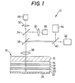
- a magneto-optical apparatus of the invention for reading information from a magneto-optical memory medium of the invention in the form of a magneto-optical memory disk 10.
- the mangeto-optical memory disk 10 consists of a laminar structure comprising a non-magnetic layer 14, a first magneto-optical storage layer 16, an intermediate non-magnetic layer 18, a second magneto-optical storage layer 20, another non-magnetic layer 22 and a reflector layer 24, which are formed in this order on one surface of a transparent substrate layer 12, with vapor deposition, sputtering or other suitable known methods.
- the transparent substrate layer 12 may be formed of a glass material, transparent resin, or other suitable transparent material.
- the substrate layer 12 is made of an acrylic resin such as polymethyl methacrylate (PMMA).
- PMMA polymethyl methacrylate
- the use of acrylic resins for the substrate layer 12 facilitates the manufacture of the memory disk 10, and permits easy handling of the same.
- the non-magnetic layers 14, 22 are provided to protect the first and second thin magneto-optical storage layers 16 and 20, and are formed of a transparent non-magnetic or dielectric material such as aluminum nitride (AlN), silicon oxide (SiO), silicon dioxide (Si0 2 ), or metallic silicon (Si). More specifically, the non-magnetic layers 14, 22 protect the first and second storage layers 16, 20 from their chemical change (oxidation, etc.), and have 0 0 thicknesses of about 1421A and 1336A, respectively.
- AlN aluminum nitride
- SiO silicon oxide
- Si0 2 silicon dioxide
- Si metallic silicon
- first and second storage magneto-optical layers 16, 20 are separated by the intermediate non-magnetic layer 18, and the laminar structure of these three layers 16, 18, 20 are sandwiched by the non-magnetic layers 14, 22.
- the first magneto-optical storage layer 16 has a thickness of about 0 110A
- the second magneto-optical storage layer 20 has a 0 thickness of about 800A
- the intermediate non-magnetic layer 18 has a thickness of about 17830A.
- the first and second storage layers 16, 20 are formed of magneto-optical materials having an excellent magneto-optical effect.
- the storage layers 16, 20 may be formed of amorphous GdTbFe, TbFe, TbFeCo, GdCo or GdDyFe, polycrystalline MnCuBi, monocrystalline TbFeO 3 , or rare earth iron garnet.
- the storage layers 16, 20 are made of GdTbFe.
- the intermediate non-magnetic layer 18 is made of a translucent non-magnetic or dielectric material as used for the non-magnetix layer 14.
- the layer 18 may be a liminar structure consisting of a plurality of translucent non-magnetic films. This laminar structure is preferred for easy formation of the non-magnetic layer 18 with a large thickness.
- the laminar non-magnetic layer 18 may be formed by alternate films of Si0 2 and SiO.
- the reflector layer 24 is made of various materials which reflect light, typically a layer of aluminum formed by vapor deposition.
- the non-magnetic layer 22 and the reflector layer 24 may be replaced by a plastic layer having a large thickness.
- a relatively thick plastic layer may serve to sufficiently reflect incident light at its interface with the magneto-optical storage layer 20, and may function at the same time to protect the storage layer 20 from oxidation.
- the magneto-optical memory disk 10 is rotated by a driving device (not shwon) about its axis which is oriented vertically, for example.
- the magneto-optical reading apparatus 11 has an optical system including an object lens 38.
- the optical system is adapted to be movable relative to the memory disk 10 in a horizontal plane and in a radial direction of the memory disk 10, so that a beam of light incident to the memory disk 10 for information reproduction may be moved in the radial direction of the disk 10.
- the optical system further includes first and second laser light sources 26 and 28 which emit laser beams of different wavelengths in the form of linearly polarized light, such that the laser beams are directed to a dichroic mirror 34 through collimator lenses 30, 32, respectively.
- the laser beam (hereinafter referred to as "first laser beam”) produced by the first laser light source 26 has a wavelength Xl of 8300A
- the laser beam (hereinafter called “second laser beam”) of the second laser light 0 source 28 has a wavelength X2 of 7800A
- the dichroic mirror 34 permits the first laser beam of the wavelength Xl to pass therethrough, and reflects the second laser beam of the wavelength X2.
- the composite laser of the wavelengths ⁇ 1 and X2 from the dichoric mirror 34 is transmitted through a half mirror 36 and the object lens 38 positioned opposite to the memory disk 10, whereby the composite laser beam is incident to the memory disk 10.
- the optical system includes the laser light sources 26, 28, collimator lenses 30, 32, dichroic mirror 34 and object lens 38, which cooperate with each other to apply laser beams to the magneto-optical memory disk 10 for reading information therefrom.
- the composite laser beam incident to the memory disk 10 is reflected by the reflector layer 24, and transmitted to a dichroic mirror 40 through the object lens 38 and the half mirror 36.
- the dichoric mirror 40 permits the first laser beam to pass therethrough, and reflects the second laser beam, whereby the composite laser beam from the half mirror 36 is separated.
- the first and second laser beams of the wavelengths Xl and X2 are received by a first and a second detecting device 42, 44, respectively.
- the first and second detecting devices 42, 44 detect angles of the Kerr rotation of the first and second laser beams of the different wavelengths ⁇ 1, and X2, respectively.
- the Kerr rotation angles of the first and second laser beams ( ⁇ 1, X2) are changed depending upon the magneto-optical anisotropy or the direction of magnetization of the parts of the first and second magneto-optical storage layers 16, 20 which are exposed to the laser beams. Therefore, by detecting the Kerr rotation angle of the first or second laser beam, it is possible to reproduce the information which has been recorded in the first or second storage layer 16, 20 by means of magnetization of each memory location thereof in one of opposite directions perpendicular to the surface of the memory disk 10.
- the object lens 38, half mirror 36, dichroic mirror 40, first detecting device 42, and second detecting device 44 cooperate to constitute a detecting device for detecting angles of the Kerr rotation of the first and second laser beams.
- the detecting devices 42, 44 are identically constructed.
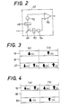
- the first detecting device 42 is illustrated in Fig. 2, whrein the first laser beam of the wavelength ⁇ 1 reflected by the memory disk 10 is split by a half mirror 46 into two beams one of which is received by a photodiode 52 through an analyzer 48, and the other of which is received by a photodiode 54 through an analyzer 50.
- the analyzers 48 and 50 have planes of polarization which are perpendicular to each other, and are inclined 45 degrees with respect to a plane of polarization of the incident laser beams.
- the rotation of the polarization plane of the first laser beam will cause, for example, an increase in the amount of light received by the photodiode 52, and a decrease in the amount of light received by the photodiode 54.
- Outputs of the photodiodes 52, 54 are applied to corresponding inputs of a differential amplifier 56, which provides an output representative of the information stored on the first magneto-optical storage layer 16.
- This differential amplifier 56 eliminates noises due to output variations of the laser light sources 26, 28. While the present embodiment uses the laser light sources 26, 28 of semiconductor or external resonance type for producing linearly polarlized laser beams, it is possible to use laser sources of internal resonance type which produce circularly polarized light. In this case, the laser beams emitted from the laser sources are applied through a polarizer.
- the operation of the instant magneto-optical reading apparatus 11 will be described.
- the information stored in the first storage layer 16 of the memory disk 10, and the information stored in the second storage layer 20 spaced from the first storage layer 16 by the intermediate non-magnetic layer 18, are read out independently of each other.
- an amount of change in the Kerr rotation angle of the first laser beam should represent the direction of magnetization (N or S) of the fisrt storage layer 16 as indicated at (a) and (b) in Fig. 3, irrespective of the direction of magnetization of the second storage layer 20.
- an amount of change in the Kerr rotation angle of the second laser beam should represent the direction of magnetization (N or S) of the second storage layer 20 as indicated at (a) and (b) in Fig. 4, irrespective of the direction of magnetization of the first storage layer 16.
- the inventor of the present invention has obtained the following findings in connection with an amount of change or difference in the Kerr rotation angle of each of the first and second laser beams of the different wavelengths ⁇ 1 and X2, depending upon the four possible combinations of the magnetization directions of the first and second magneto-optical storage layers 16, 20. More specifically stated, it was found that the Kerr rotation angles of the four combinations with respect to each other are changed differently as the thickness of one of the first and second storage layers 16, 20 is changed.
- the curves show differences in the Kerr rotation angle of the four combinations N/S, N/N, S/N and S/S of the magnetization directions of the first and second storage layers 16, 20, relative to each other.
- the curves N/S and N/N indicate the cases where the first storage layer 16 is magnetized in the N direction, while the second storage layer 20 is magnetized in the S and N directions, respectively.
- the curves S/N and S/S indicate the cases where the first storage layer 16 is magnetized in the S direction, while the second storage layer 20 is magnetized in the N and S directions, respectively.
- an amount of change in the Kerr rotation angle of the first laser beam among the four combinations N/S, N/N, S/N, S/S relative to each other distinctly represents the magnetizating direction of the first storage layer 16, irrespective of the magnetizating direction of the second storage layer 20, if the first storage layer 16 has a 0 thickness in the neighbourhood of 100A.
- the Kerr roation angle is changed by an approximate amount of 0.6 degrees ( ⁇ k) when the magnetizating direction of the first storage layer 16 is changed from S to N, regardless of whether the second storage layer 20 is magnetized in the N or S direction.
- an amount of change in the Kerr rotation angle of the second laser beam among the four combinations N/S, N/N, S/N, S/S relative to each other distinctly represents the magnetizating direction of the second storage layer 20, irrespective of the magnetizating direction of the first storage layer 16, if the first storage layer 16 has a 0 thickness in the neighbourhood of 120A.
- the first magneto-optical storage layer 16 of the memory disk 10 has a thickness of 0 100A. Accordingly, a difference or change in the Kerr rotation angle of the first laser beam reflected by the memory disk 10, which is obtained due to the magneto-optical anisotropy (N or S) of the first storage layer 16, identifies one of the opposite magnetizating directions (N or S) of the first storage layer 16, with a sufficiently high level of distinction. Therefore, the detection of the Kerr rotation angle of the first storage layer 16 by the first detecting device 42 enables the reading apparatus 11 to provide an output signal which indicates the information (N or S) stored on a part of the first storage layer 16 to which the first laser beam is incident.
- a change in the Kerr rotation angle of the second laser beam reflected by the disk 10 permits reliable identification of the magnetizating direction of the second storage layer 20, and the detection of the Kerr rotation angle of the second storage layer 20 by the second detecting device 44 enables the reading apparatus 11 to provide an output signal indicative of the information stored on the corresponding part of the second storage layer 20.
- the instant magneto-optical reading apparatus 11 is capable of reading out information selectively from the first and second magneto-optical storage layers 16, 20, as needed.
- the density of information recordable on the memory disk 10, i.e., the amount of information that can be stored on the memory disk 10 is almost doubled, as compared with that of a known magneto-optical disk having a single storage layer. This is a drastic increase in the memory capacity of the disk.
- Equation (1) is obtained by using Maxwell's electromagnetic equations. Conditions of each of the layers of the magneto-optical memory disk 10 are applied to the Maxwell's equations to obtain relations between incident and reflected light beams when linearly polarlized light is incident to the memory disk 10. Based on these obtained relations, an angle ⁇ of the Kerr rotation of the reflected light beam is expressed by Equation (1), provided an electric field strength of the reflected light beam consists of a component Ey having the a polarization plane parallel to that of the incident light beam, and a component Ex having a polarization plane perpendicular to that of the reflected light beam.
- the relative amount of change (68k) of Figs. 5 and 6 is expressed as a difference from the minimum value of the four values of the Kerr rotation angle ⁇ , since the angle ⁇ is changed depending upon the directions of magnetization of the first and second storage layers 16, 20.
- Equations (7) and (8) the components
- Equation (12) The matrices of Equation (12) are expressed by Equations (13) through (18), respectively, wherein the following definitions are given:
- the characteristic curves shown in Figs. 5 and 6 are obtained where the first storage layer 16 of the memory disk 10 is formed of GdTbFe. If other materials are used for the first storage layer 16, the characteristic relations between the Kerr rotation angles of the first and second laser beams and the thickness of the first storage layer 16 will be obviously changed accordingly. Therefore, it will be understood that the optimum thickness of the first storage layer 16 of the memory disk 10 must be changed accordingly.
- the instant embodiment uses the first storage layer 16 as a layer whose thickness is determined according to the concept of the invention, it is possible that the thickness of the second storage layer 20 is determined so as to permit reliable detection of the magnetization directions of the layers 16, 20 based on the amount of change in the Kerr rotation angles.
- the magneto-optical memory disk 10 may comprise three or more magneto-optical storage layers, as illustrated in Fig. 7 wherein a second intermediate non-magnetic layer 58 and a third magneto-optical storage layer 60 are interposed between the second storage layer 20 and the non-magnetic layer 22.
- a second intermediate non-magnetic layer 58 and a third magneto-optical storage layer 60 are interposed between the second storage layer 20 and the non-magnetic layer 22.
- three laser beams of different wavelengths are necessary to read out information from selected one of the three magneto-optical storage layers 16, 20 and 60.
- the memory disk 10 of Fig. 7 has a memory capacity about three times as large as a conventional memory disk with a single storage layer.
- each of the storage layers 16, 20 of the memory disk 10 may consists of a plurality of magneto-optical films superposed in direct contact with each other without a non-magnetic layer interposed therebetween.
- each of the storage layers 16, 20 consists of a GdFe film 62 and a TbFe film 64, as illustrated in Fig. 8.
- the TbFe film 64 has a comparatively low Curie point, so that information may be written with a relatively low level of electric power.
- the GdFe film 62 which is magnetically connected to the TbFe film 64, has a comparatively large magneto-optical effect, which therefore permits easier writing and reading of information on and from the storage layer 16, 20.
- the illustrated memory medium 10 in the form of a disk may be replaced by a magneto-optical memory medium of other shapes such as a tape or drum.
- the two laser light sources 26, 28 are provided for producing the first and second laser beams of different wavelengths Xl and a2.
- a semiconductor laser array, argon laser device or other light source devices which generate beams of different wavelengths, or a chromatic light source emitting a light beam of a variable wavelength.
- the information reproduction may be accomplished with a single light source, or a plurality of light sources which is smaller in number than the magneto-optical storage layers of the memory disk 10.
- wavelengths ⁇ 1 and ⁇ 2 of the first and second laser beams produced by the laser light sources 26, 0 0 28 are 8300A and 7800A, respectively, which are readily obtainable with a commercially available semiconductor laser element, it will be understood that the wavelengths of the laser beams of the light sources 26, 28 may be changed as desired.
- the first and second laser beams of the wavelengths ⁇ 1 and X2 are used corresponding to the first and second storage layers 16, 20, so that the information stored on these layers 16, 20 may be read out by detecting amounts of change in the Kerr rotation angle of the first and second laser beams, respectively.
- the information may be reproduced, for example, by obtaining a signal representative of a sum of changes of the Kerr rotation angles of the first and second laser beams ( ⁇ l) and (X2) incident to the first and second storage layers 16, 20, and a signal representative of a difference between these changes of the Kerr rotation angles, and processing these signals to detect the information stored on the first and second storage layers 16, 20.
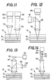
- the recording apparatus comprises a laser light source 66 which includes a collimator lens and produces a laser beam.
- the laser beam is directed to the memory disk 10 through an object lens 70 which is supported at one end of an object-lens sleeve 68.
- the apparatus further comprises a frame 67 which carries a positioning mechanism 69 for positioning the object-lens sleeve 68 relative to the memory disk 10.
- the sleeve 68 carries a drive coil 71 wound in the form of a ring, so that the sleeve 68 is movable with an electromagnetic force of the coil 71 between a first position near the memory disk 10, and a second position remote from the memory disk 10.
- the sleeve 68 is supported by the frame 67 through sheet springs 73, so that the sleeve 68 is movable along an optical axis of the object lens 70 (in the vertical direction of Fig. 9), relative to the frame 67.
- To the frame 67 are attached an annular permanent magnet 75, and yoke members 77, 79, such that the coil 71 on the sleeve 68 is located in a magnetic field produced between the two yoke members 77, 79.
- the object lens 70 is moved to a position corresponding to an amount of an electric current applied to the coil 71.
- the positioning mechanism 69 serves as positioning means for positioning the object lens 70 relative to the memory disk 10 so that the laser beam produced by the laser light source 66 is converged selectively on the first and second storage layers 16, 20.
- the positioning mechanism 69 serves as selector means for positioning a focal point of the laser beam on selected one of the storage layers 16, 20.
- the object lens 70 has a depth of focus 6f which 0 is smaller than the thickness (17830A) of the intermediate non-magentic layer 18 of the magneto-optical memory disk 10. It is known that the depth of focus ⁇ f of the object lens 70 is given by Equation (19):
- the wavelength ⁇ fo the laser beam emitted from the light source 66 is 0.83 ⁇ m
- the numerical aperture NA of the object lens70 is 0.6
- the depth of focus 6f is calculated as: ⁇ f ⁇ 0.7 ⁇ m. Therefore, when the object lens 70 is positioned at the first position near the memory disk 10, the laser beam from the laser light soource 66 is converged on a part of the second storage layer 20 of the memory disk 10, whereby the magneto-optical material of the second storage layer 20 is heated beyond its Curie point. Thus, the information stored on the heated part is erased.
- the recording apparatus further comprises magnetic-field generating means including an electromagnet 74 for producing a magnetic field in a direction perpendicular to the memory disk 10.
- the cooled beam spot is magnetized in one of the opposite directions perpendicular to the surface of the memory disk 10, depending upon the direction of the magnetic field produced by the electromagnet 74. In this manner, desired information may be written at a desired part or spot (beam spot) of the second storage layer 20 of the memory disk 10.
- the laser beam for erasing the information on the second storage layer 20 is transmitted through the first storage layer 16, the corresponding part of the first storage layer 16 will not be heated above its Curie point, because the depth of focus 6f of the object lens 70 is selected to be sufficiently smaller than the thickness of the intermediate non-magnetic layer 18.
- the first storage layer 16 is protected against erasure of its information upon earsure of information on the second storage layer 20.
- the object lens 70 Upon energization of the coil 71, the object lens 70 is moved to the second postion remote from the memory disk 10 as shown in Fig. 10, the laser beam from the light source 66 is converged on a part of the first storage layer 16 of the memory disk 10. Accordingly, the information recorded on the heated part is erased, and new information may be written thereon, in the same manner as described previously. In this case, too, the laser beam for erasing the information on the first storage layer 16 passes through the second storage layer 20. However, the dpeth of focus 6f of the object lens 70 which is smaller than the thickness of the intermediate non-magnetic layer 18, contributes to preventing the laser beam from heating the corresponding part of the second storage layer 20 to a temperature over its Curie point.
- the instant recording apparatus is adapted such that the object lens 70 is moved toward and away from the stationary memory disk 10, it is possible that the memory disk 10 is moved with respect to the object lens 70.
- the linearly polarized light from the light source may be replaced by circularly polarized light, since the laser beam from the light source 66 is used to locally heat the first and second storage layers 16, 20. Further, a monochromic light beam may be substituted for the laser beam from the light source 66.
- the erasing and writing operations of the first and second storage layers 16, 20 may be effected at the same position as viewed in a plane parallel to the memory disk 10.
- Another advantage of this embodiment is the elimination of a drive device for positioning the object lens 70 relative to the memory disk 10 along the optical axis of the object lens 70.
- FIG. 13 A further modified embodiment is illustrated in Fig. 13, wherein the object lens 70 is positioned stationary with respect to the memory disk 10 in the direction perpendicular to the memory disk.
- a pair of laser light sources 80, 82, and a pair of collimator lenses 84, 86 are disposed, so that a first laser beam from the light source 80 is transmitted through the collimator lens 84, a half mirror 88 and the object lens 70 and is converged on the first storage layer 16, while a second laser beam from the light source 82 is transmitted through the collimator lens 86, reflected by the half mirror 88, and converged by the object lens 70 on the second storage layer 20 of the memory disk 10.
- the two laser beams from the two laser light sources are selectively incident to the memory disk 10 according to a currently selected circumferential position of the memory disk 10, i.e., while the memory disk 10 is rotated.
- shutters 67 as indicated in Fig. 11 or a power switch 83 may be provided for selective application of the two laser beams to the corresponding first and second storage layers 16, 20.
- the shutters 67 are associated with the light sources 66, 66 to shut one of the laser beams, for allowing application of only one of the laser beams corresponding to one of the first and second storage layers 16, 20 on which information will be written.
- the power switch 83 selectively activates one of the first and second laser light sources 80, 82 to emit the corresponding laser beam to one of the storage layers 16, 20.
- FIG. 14 A still further embodiment of a recording apparatus is illustrated in Fig. 14, wherein a collimator lens 90 and the object lens 70 are positioned stationary relative to the memory disk 10 in the direction perpendicular to the disk 10.
- a laser light source 92 is adapted to be movable along the optical axis of the object lens 70 so that the laser beam from the light source 92 is coverged selectively on the first or second storage layer 16, 20 of the memory disk 10.
- the light source 92 is attached to a slide 98 which engages a lead screw 96 driven by a stationary drive motor 94.
- the slide 98 With the screw 96 rotated, the slide 98 is moved parallel to the screw 96, whereby the light source 92 is moved toward or away from the collimator lens 90 and object lens 70, along their optical axes.
- the slide 98 may be driven by the positioning mechanism 69 of Fig. 9, or by an electrostrictive or magnetostrictive element.
- a magneto-optical memory disk 100 which, like the memory disk 10, includes the first and second storage layers 16, 20 separated by the intermediate non-magnetic layer 18, the layers 16, 20, 18 being formed on the transparent substrate layer 12.
- the first and second storage layers 16, 20 are made of magneto-optical materials the Curie points of which are different from each other.
- the first storage layer 16 is made of GdDyFe having a Curie point of about 120°C
- the second storage layer 20 is made of GdTbFe having a Curie point of about 150°C.
- a laser light source 101 for example, a laser beam 106 directed to the memory disk 100 through the object lens 104 has a wavelength of 0.83 ⁇ m and a numerical aperture NA of 0.45.
- the depth of focus 6f of the object lens 104 is obtained from Equation (9) as ⁇ 1.3 um, that is 2.6 ⁇ m.
- the thickness of the intermediate non-magnetic layer 18 is 2.5 um or smaller.
- the thickness of the layer 18 is 17830A.
- information may be written simultaneously on the first and second storage layers 16, 20 in the following manner.
- the coil 102 is energized to form a magnetic field in the direction indicated at M in Fig. 15.
- a power source 103 to apply power to the light source 101 is set in its high output position to activate the light source 101, so that the laser beam of high intensity is produced from the light source 101 and directed to the memory disk 100. Consequently, the appropriate parts of the first and second storage layers 16, 20 are heated to a temperature beyond 150 o C , for example, whereby the already stored information are erased from the heated parts of the layers 16, 20, and these parts are magnetized in the direction M of the magnetic field. Thus, new information is written on the same parts of the first and second storage layers 16, 20.
- the power source 103 is placed in its low output position, so that the intensity of the laser beam 106 incident to the memory disk 100 is reduced. More specifically, the intensity of the laser beam 106 is adjusted so tht the temperature of the parts of the storage layers 16, 20 at which the laser beam 106 is converged, is held within a range of 120-150°C. Accordingly, the appropriate part of the first storage layer 16 is heated to the temperature beyond its Curie point.
- the intensity of the laser beam 106 may be changed by adjusting an electric current supplied from the power source 103 to the light source 101, or by adjusting a duty cycle of drive pulses applied to the light source 101.
- the output of the light source 101 may be adjusted by changing a filter through which the laser beam 106 passes.
- Reference numeral 112 in Fig. 18 indicates the part on which the new information is written as described above. If the coil 102 in the position of Fig. 17 is energized in the reverse direction, the appropriate part of the first layer 16 is magnetized in the reverse direction, as indicated at 114 in Fig. 18.
- the memory disk 100 may have three or more magneto-optical storage layers having different Curie points. In this case, too, the information recording on the individual storage layers may be effected in the same manner as described above.
- the two or more elements such as the lens and half mirror may be provided as a single composite element.
- the half mirror 76, 88 may be replaced by a dichroic mirror or a polarizing prism, and the dichoric mirror 34, 40 may be replaced by a combination of a half mirror and a filter. In the latter case, however, the operating efficiency of the optical system is slightly reduced.
- the magneto-optical recording and reading apparatus have been illustrated as separate devices, for easy understanding of the invention, the recording and reading apparatus are generally provided as a single apparatus.
- the laser light sources used in the illustrated embodiments may be used for both recording and reading operations, if the output capacity of these sources may be increased as required. Therefore, the illustrated magneto-optical reading system may be used for magneto-optical recording operations.
- the recording apparatus as illustrated include only the elements which are necessary for a magneto-optical recording operation, while the reading apparatus as illustrated include only the elements which are necessary for a magneto-optical reading operation.
Applications Claiming Priority (8)
| Application Number | Priority Date | Filing Date | Title |
|---|---|---|---|
| JP22874184A JPH0666094B2 (ja) | 1984-10-30 | 1984-10-30 | 光磁気記録装置 |
| JP228743/84 | 1984-10-30 | ||
| JP228741/84 | 1984-10-30 | ||
| JP228744/84 | 1984-10-30 | ||
| JP22874484A JPS61107553A (ja) | 1984-10-30 | 1984-10-30 | 光磁気再生装置 |
| JP22874384A JPS61107552A (ja) | 1984-10-30 | 1984-10-30 | 光磁気記録媒体 |
| JP22874284A JPH0666095B2 (ja) | 1984-10-30 | 1984-10-30 | 光磁気記録装置 |
| JP228742/84 | 1984-10-30 |
Publications (3)
| Publication Number | Publication Date |
|---|---|
| EP0180459A2 true EP0180459A2 (de) | 1986-05-07 |
| EP0180459A3 EP0180459A3 (en) | 1987-08-12 |
| EP0180459B1 EP0180459B1 (de) | 1991-12-18 |
Family
ID=27477338
Family Applications (1)
| Application Number | Title | Priority Date | Filing Date |
|---|---|---|---|
| EP85307828A Expired EP0180459B1 (de) | 1984-10-30 | 1985-10-29 | Magnetooptisches Speichermedium und Gerät zum Schreiben auf und Lesen von dem Medium |
Country Status (3)
| Country | Link |
|---|---|
| US (1) | US4922454A (de) |
| EP (1) | EP0180459B1 (de) |
| DE (1) | DE3584945D1 (de) |
Cited By (18)
| Publication number | Priority date | Publication date | Assignee | Title |
|---|---|---|---|---|
| GB2184618A (en) * | 1985-12-11 | 1987-06-24 | Canon Kk | Magneto-optical memory medium |
| GB2192750A (en) * | 1986-07-14 | 1988-01-20 | Canon Kk | Front loading opto-magnetic recording apparatus with bias magnetic field means retractable from medium insertion path |
| EP0304288A1 (de) * | 1987-08-21 | 1989-02-22 | Kabushiki Kaisha Toshiba | Magnetooptisches Informationsspeichermedium und Verfahren zum Informationsaufzeichnen und Löschen |
| WO1989001688A1 (en) * | 1987-08-12 | 1989-02-23 | Digital Equipment Corporation | Improved apparatus for magneto-optical recording |
| EP0288069A3 (en) * | 1987-04-24 | 1989-03-29 | Sony Corporation | Thermomagnetic recording method applying a power modulated laser beam on a magnetically coupled multi-layer structure of a perpendicular anisotropy magnetic film |
| AU593127B2 (en) * | 1986-08-20 | 1990-02-01 | Sony Corporation | Thermo-magnetic recording method applying power modulated laser on magnetically coupled double layer structure of perpendicular antisotropy film |
| US4928192A (en) * | 1987-12-23 | 1990-05-22 | Konica Corporation | Process for identifying disks and automatically configuring a disk drive system |
| EP0285461A3 (en) * | 1987-04-03 | 1990-09-12 | Mitsubishi Denki Kabushiki Kaisha | Magneto-optic recording and reproduction apparatus |
| EP0285241A3 (en) * | 1987-04-03 | 1990-09-19 | Mitsubishi Denki Kabushiki Kaisha | Magneto-optic information-carrying medium |
| EP0318925A3 (en) * | 1987-11-30 | 1990-09-26 | Sony Corporation | Method for optically reproducing a signal from magneto-optical recording medium |
| EP0401041A3 (de) * | 1989-06-02 | 1991-05-15 | Nippon Hoso Kyokai | Aufzeichnungsträger, Aufnahme- und Wiedergabegerät und Aufnahmeverfahren |
| FR2680037A1 (fr) * | 1991-07-31 | 1993-02-05 | Sagem | Support d'enregistrement de donnees a lecture magneto-optique et procede et dispositif d'enregistrement et de lecture en comportant application. |
| US5187694A (en) * | 1987-08-21 | 1993-02-16 | Kabushiki Kaisha Toshiba | Magneto-optical recording medium comprising recording layer and thermal bias layer, and method for recording, erasing and overwriting on the medium |
| EP0530728A3 (en) * | 1991-09-02 | 1993-10-06 | Nippon Hoso Kyokai | Magneto-optical memory device for multi-wavelength recording and reproduction |
| EP0745979A3 (de) * | 1995-05-31 | 1997-01-22 | Daewoo Electronics Co., Ltd | Optisches Abtastgerät mit einem Objektivlinsenpositioniersystem |
| EP0762412A1 (de) * | 1995-08-25 | 1997-03-12 | Eastman Kodak Company | Optisches Speichermedium, das mehrere Datenebenen von Co/Pt magneto-optischen Aufzeichnungsmedien enthält |
| EP0723264A3 (de) * | 1995-01-19 | 1997-06-25 | Ibm | Magnetooptisches Datenspeicherungssystem mit mehreren Datenflächen |
| CN105866506A (zh) * | 2016-04-01 | 2016-08-17 | 河北大学 | 一种利用磁光材料测量导体电流的装置及方法 |
Families Citing this family (30)
| Publication number | Priority date | Publication date | Assignee | Title |
|---|---|---|---|---|
| US6028824A (en) * | 1986-07-08 | 2000-02-22 | Canon Kabushiki Kaisha | Magnetooptical recording medium allowing overwriting with two or more magnetic layers |
| EP0838814B1 (de) * | 1986-07-08 | 2002-02-27 | Canon Kabushiki Kaisha | Magnetooptisches Aufzeichnungsmedium mit der Möglichkeit des Überschreibens mit zwei oder mehr Magnetschichten und dieses Medium verwendende Aufzeichnungsmethode |
| US5270987A (en) * | 1988-02-08 | 1993-12-14 | Hitachi, Ltd. | Magneto-optical recording and reproducing method, magneto-optical memory apparatus and magneto-optical recording medium therefor |
| US5073888A (en) * | 1988-04-21 | 1991-12-17 | Ricoh Company, Ltd. | Optical pickup device |
| JPH0227545A (ja) * | 1988-07-15 | 1990-01-30 | Canon Inc | 光磁気記録層及びその成膜方法 |
| NL8900362A (nl) * | 1989-02-15 | 1990-09-03 | Philips Nv | Werkwijze en inrichting voor het inschrijven en uitlezen van een magneto-optische registratiedrager. |
| JP2685888B2 (ja) * | 1989-04-07 | 1997-12-03 | シャープ株式会社 | 磁気光学記録媒体 |
| NL8902293A (nl) * | 1989-09-14 | 1991-04-02 | Philips Nv | Werkwijze en inrichting voor het inschrijven en uitlezen van een magneto-optische registratiedrager. |
| DE69027103T2 (de) * | 1989-11-22 | 1996-10-24 | Sharp Kk | Optisches Aufzeichnungsmedium und Verfahren zur Aufzeichnungs und Wiedergabe von Informationen darauf |
| JP2574911B2 (ja) * | 1990-01-10 | 1997-01-22 | シャープ株式会社 | 光磁気記録方法 |
| US5184322A (en) * | 1990-01-29 | 1993-02-02 | Nathan Okun | Optical storage device with a stationary mass storage medium |
| US5392263A (en) * | 1990-01-31 | 1995-02-21 | Sony Corporation | Magneto-optical disk system with specified thickness for protective layer on the disk relative to the numerical aperture of the objective lens |
| JP2861188B2 (ja) * | 1990-01-31 | 1999-02-24 | ソニー株式会社 | 光磁気記録再生装置 |
| US5587990A (en) * | 1990-01-31 | 1996-12-24 | Sony Corporation | Optical disc system and optical disc therefor |
| EP0448919B1 (de) * | 1990-03-26 | 1996-02-14 | International Business Machines Corporation | Datenträger |
| CA2043995C (en) * | 1990-06-13 | 1997-06-24 | Kenji Ohta | Magneto-optical recording/reproducing device |
| EP0470862B1 (de) * | 1990-08-10 | 1996-03-27 | Research Development Corporation Of Japan | Verfahren und Aufzeichnungsträger für magnetooptische Aufzeichnung |
| US5282095A (en) * | 1991-04-24 | 1994-01-25 | U.S. Philips Corporation | Direct over-write magneto-optical recording medium having multiple recording layers, and method of recording new information by directly overwriting pre-existing recorded information on such medium |
| US5255262A (en) * | 1991-06-04 | 1993-10-19 | International Business Machines Corporation | Multiple data surface optical data storage system with transmissive data surfaces |
| US5910932A (en) * | 1991-09-11 | 1999-06-08 | Sony Corporation | Optical disk and optical disk system with numerical aperture of objective lens related to protective layer thickness of optical disk |
| US5838646A (en) * | 1991-09-11 | 1998-11-17 | Sony Corporation | Optical disk having a protective layer of specified thickness relative to the numerical aperture of the objective lens |
| US5554451A (en) * | 1991-09-27 | 1996-09-10 | Brother Kogyo Kabushiki Kaisha | Optical data recording medium |
| US7286153B1 (en) * | 1991-10-11 | 2007-10-23 | Hitachi, Ltd. | Three-dimensional recording and reproducing apparatus |
| JPH05210868A (ja) * | 1992-01-30 | 1993-08-20 | Hitachi Ltd | マルチビーム分離形光ヘツド |
| US5361248A (en) * | 1992-06-01 | 1994-11-01 | Eastman Kodak Company | Direct overwrite magneto-optical storage medium not requiring an initialization magnet |
| US5381390A (en) * | 1993-06-03 | 1995-01-10 | Eastman Kodak Company | Directly overwrite information by using two radiation beams onto a single magneto-optical recording |
| US5648163A (en) * | 1994-09-27 | 1997-07-15 | Imation Corp. | Magneto-optic recording medium having magneto-optic film layers separated by yttrium oxide |
| US5914915A (en) * | 1995-02-03 | 1999-06-22 | Sony Corporation | Magneto-optical disk system having an objective lens with a numerical aperture related to the thickness of the protective layer |
| US6226233B1 (en) | 1996-07-30 | 2001-05-01 | Seagate Technology, Inc. | Magneto-optical system utilizing MSR media |
| KR100268486B1 (ko) * | 1997-11-01 | 2000-10-16 | 윤종용 | 광디스크기록및재생방법과그장치 |
Family Cites Families (17)
| Publication number | Priority date | Publication date | Assignee | Title |
|---|---|---|---|---|
| US3235672A (en) * | 1961-11-17 | 1966-02-15 | American Optical Corp | Optical sound recording and reproduction |
| US3665483A (en) * | 1969-06-06 | 1972-05-23 | Chase Manhattan Capital Corp | Laser recording medium |
| US3650601A (en) * | 1970-11-19 | 1972-03-21 | Du Pont | Magneto-optic device having alternate layer film structure |
| US3781905A (en) * | 1972-09-22 | 1973-12-25 | Honeywell Inc | Optical mass memory |
| US4219704A (en) * | 1974-10-21 | 1980-08-26 | Eli S. Jacobs | Record playback apparatus for optical data records |
| NL7803069A (nl) * | 1978-03-22 | 1979-09-25 | Philips Nv | Meerlaags informatieschijf. |
| JPS5668937A (en) * | 1979-11-06 | 1981-06-09 | Matsushita Electric Ind Co Ltd | Optical disk reproducing device |
| NL8101932A (nl) * | 1981-04-21 | 1982-11-16 | Philips Nv | Inrichting voor het inschrijven en uitlezen van informatiesporen in een optische registratiedrager. |
| JPS5883346A (ja) * | 1981-11-10 | 1983-05-19 | Kokusai Denshin Denwa Co Ltd <Kdd> | 光磁気記録媒体 |
| JPS58125244A (ja) * | 1982-01-20 | 1983-07-26 | Alps Electric Co Ltd | 光学ヘツド |
| JPS58150146A (ja) * | 1982-03-02 | 1983-09-06 | Nec Corp | 光デイスク用光ピツクアツプ |
| JPS58179904A (ja) * | 1982-04-15 | 1983-10-21 | Pioneer Electronic Corp | 情報記録方式 |
| JPS5952443A (ja) * | 1982-09-14 | 1984-03-27 | Kokusai Denshin Denwa Co Ltd <Kdd> | 光磁気記録媒体 |
| WO1984002603A1 (fr) * | 1982-12-23 | 1984-07-05 | Sony Corp | Procede d'enregistrement/reproduction optique thermomagnetique |
| US4660190A (en) * | 1983-01-25 | 1987-04-21 | Sharp Kabushiki Kaisha | Optical focus position control in optical disc apparatus |
| JPS61107553A (ja) * | 1984-10-30 | 1986-05-26 | Brother Ind Ltd | 光磁気再生装置 |
| US4635076A (en) * | 1985-03-14 | 1987-01-06 | Minnesota Mining And Manufacturing Company | Two-sided optical recording medium |
-
1985
- 1985-10-29 DE DE8585307828T patent/DE3584945D1/de not_active Expired - Lifetime
- 1985-10-29 US US06/792,591 patent/US4922454A/en not_active Expired - Lifetime
- 1985-10-29 EP EP85307828A patent/EP0180459B1/de not_active Expired
Cited By (26)
| Publication number | Priority date | Publication date | Assignee | Title |
|---|---|---|---|---|
| GB2184618A (en) * | 1985-12-11 | 1987-06-24 | Canon Kk | Magneto-optical memory medium |
| GB2192750A (en) * | 1986-07-14 | 1988-01-20 | Canon Kk | Front loading opto-magnetic recording apparatus with bias magnetic field means retractable from medium insertion path |
| US4993009A (en) * | 1986-07-14 | 1991-02-12 | Canon Kabushiki Kaisha | Opto-magnetic recording apparatus with a bias magnetic field generating means movable parallel to a recording surface of a recording medium |
| GB2192750B (en) * | 1986-07-14 | 1991-01-23 | Canon Kk | Front loading opto-magnetic recording apparatus with bias magnetic field generating means retractable from medium insertion path |
| AU593127B2 (en) * | 1986-08-20 | 1990-02-01 | Sony Corporation | Thermo-magnetic recording method applying power modulated laser on magnetically coupled double layer structure of perpendicular antisotropy film |
| US5025430A (en) * | 1987-04-03 | 1991-06-18 | Mitsubishi Denki Kabushiki Kaisha | Magneto-optic recording and reproducing apparatus including a multiple layer recording medium having a premagnetized bias layer replacing an external bias magnetic |
| US5016232A (en) * | 1987-04-03 | 1991-05-14 | Mitsubishi Denki Kabushiki Kaisha | Magneto-optic information-carrying medium including three magnetic layers |
| EP0285461A3 (en) * | 1987-04-03 | 1990-09-12 | Mitsubishi Denki Kabushiki Kaisha | Magneto-optic recording and reproduction apparatus |
| EP0285241A3 (en) * | 1987-04-03 | 1990-09-19 | Mitsubishi Denki Kabushiki Kaisha | Magneto-optic information-carrying medium |
| EP0288069A3 (en) * | 1987-04-24 | 1989-03-29 | Sony Corporation | Thermomagnetic recording method applying a power modulated laser beam on a magnetically coupled multi-layer structure of a perpendicular anisotropy magnetic film |
| US4878132A (en) * | 1987-04-24 | 1989-10-31 | Sony Corporation | Thermomagnetic recording method applying power modulated laser on a magnetically coupled multi-layer structure of perpendicular anisotropy magnetic film |
| AU600576B2 (en) * | 1987-04-24 | 1990-08-16 | Sony Corporation | Thermomagnetic recording method applying power modulated laser on a magnetically coupled multi-layer structure of perpendicular anisotropy magnetic film |
| US4965780A (en) * | 1987-08-12 | 1990-10-23 | Digital Equipment Corporation | Magneto-optical data recording device using a wavelength and polarization-sensitive splitter |
| WO1989001688A1 (en) * | 1987-08-12 | 1989-02-23 | Digital Equipment Corporation | Improved apparatus for magneto-optical recording |
| US5187694A (en) * | 1987-08-21 | 1993-02-16 | Kabushiki Kaisha Toshiba | Magneto-optical recording medium comprising recording layer and thermal bias layer, and method for recording, erasing and overwriting on the medium |
| EP0304288A1 (de) * | 1987-08-21 | 1989-02-22 | Kabushiki Kaisha Toshiba | Magnetooptisches Informationsspeichermedium und Verfahren zum Informationsaufzeichnen und Löschen |
| EP0318925A3 (en) * | 1987-11-30 | 1990-09-26 | Sony Corporation | Method for optically reproducing a signal from magneto-optical recording medium |
| US4928192A (en) * | 1987-12-23 | 1990-05-22 | Konica Corporation | Process for identifying disks and automatically configuring a disk drive system |
| EP0401041A3 (de) * | 1989-06-02 | 1991-05-15 | Nippon Hoso Kyokai | Aufzeichnungsträger, Aufnahme- und Wiedergabegerät und Aufnahmeverfahren |
| FR2680037A1 (fr) * | 1991-07-31 | 1993-02-05 | Sagem | Support d'enregistrement de donnees a lecture magneto-optique et procede et dispositif d'enregistrement et de lecture en comportant application. |
| EP0530728A3 (en) * | 1991-09-02 | 1993-10-06 | Nippon Hoso Kyokai | Magneto-optical memory device for multi-wavelength recording and reproduction |
| EP0723264A3 (de) * | 1995-01-19 | 1997-06-25 | Ibm | Magnetooptisches Datenspeicherungssystem mit mehreren Datenflächen |
| EP0745979A3 (de) * | 1995-05-31 | 1997-01-22 | Daewoo Electronics Co., Ltd | Optisches Abtastgerät mit einem Objektivlinsenpositioniersystem |
| EP0762412A1 (de) * | 1995-08-25 | 1997-03-12 | Eastman Kodak Company | Optisches Speichermedium, das mehrere Datenebenen von Co/Pt magneto-optischen Aufzeichnungsmedien enthält |
| CN105866506A (zh) * | 2016-04-01 | 2016-08-17 | 河北大学 | 一种利用磁光材料测量导体电流的装置及方法 |
| CN105866506B (zh) * | 2016-04-01 | 2018-06-22 | 河北大学 | 一种利用磁光材料测量导体电流的装置及方法 |
Also Published As
| Publication number | Publication date |
|---|---|
| DE3584945D1 (de) | 1992-01-30 |
| EP0180459A3 (en) | 1987-08-12 |
| US4922454A (en) | 1990-05-01 |
| EP0180459B1 (de) | 1991-12-18 |
Similar Documents
| Publication | Publication Date | Title |
|---|---|---|
| EP0180459B1 (de) | Magnetooptisches Speichermedium und Gerät zum Schreiben auf und Lesen von dem Medium | |
| US5577016A (en) | Recording medium having concavo-convex pits with a maximum and a minimum pit depth depending on the wavelength of a laser light | |
| US4672594A (en) | Magneto-optical recording system utilizing a leakage magnetic field of focusing actuator | |
| US4586092A (en) | Thermo-magneto-optical memory device and recording medium therefor | |
| CA1177577A (en) | Magnetooptical recording medium and recording-and- reproducing device using the same | |
| KR0168626B1 (ko) | 정보의 열자기적 기록 및 기억의 정보의 광학적 판독 방법과, 그 방법에 사용하기 적합한 기록 소자 및 기록 소자 제조방법 | |
| US4510544A (en) | Optoelectronic device for reading data contained on a magnetic medium | |
| US7113453B1 (en) | Method for recording and reproduction on a magneto-optical recording medium | |
| US4497006A (en) | Magneto-optic recording/playback head assembly | |
| US5187703A (en) | Magneto-optical multilayer recording disk and method of reproducing the same | |
| JP2861188B2 (ja) | 光磁気記録再生装置 | |
| JPH0513339B2 (de) | ||
| EP0354564B1 (de) | Magneto-optisches Aufzeichnungsmedium | |
| NL8301916A (nl) | Thermo-magneto-optische registratie-inrichting en registratie-element daarvoor. | |
| US6324148B1 (en) | Optical disk and optical information recording/reproducing apparatus | |
| JPH0513336B2 (de) | ||
| JPH0666094B2 (ja) | 光磁気記録装置 | |
| US5130958A (en) | Method of and apparatus for overwritting a magneto-optic disk | |
| JPS5971144A (ja) | 光学的情報記録媒体 | |
| JPH0666095B2 (ja) | 光磁気記録装置 | |
| EP0510758A2 (de) | Verfahren zum thermomagnetischen Aufzeichnen und optischen Auslesen von Information | |
| KR100357094B1 (ko) | 근접장 광자기 기록/재생 장치 및 방법 | |
| JPS6273442A (ja) | 磁気光学記憶素子 | |
| JPS5727450A (en) | Magnetic recording medium | |
| JPH0456363B2 (de) |
Legal Events
| Date | Code | Title | Description |
|---|---|---|---|
| PUAI | Public reference made under article 153(3) epc to a published international application that has entered the european phase |
Free format text: ORIGINAL CODE: 0009012 |
|
| AK | Designated contracting states |
Kind code of ref document: A2 Designated state(s): DE GB NL |
|
| PUAL | Search report despatched |
Free format text: ORIGINAL CODE: 0009013 |
|
| AK | Designated contracting states |
Kind code of ref document: A3 Designated state(s): DE GB NL |
|
| 17P | Request for examination filed |
Effective date: 19870916 |
|
| 17Q | First examination report despatched |
Effective date: 19891019 |
|
| GRAA | (expected) grant |
Free format text: ORIGINAL CODE: 0009210 |
|
| AK | Designated contracting states |
Kind code of ref document: B1 Designated state(s): DE GB NL |
|
| PG25 | Lapsed in a contracting state [announced via postgrant information from national office to epo] |
Ref country code: NL Effective date: 19911218 |
|
| REF | Corresponds to: |
Ref document number: 3584945 Country of ref document: DE Date of ref document: 19920130 |
|
| NLV1 | Nl: lapsed or annulled due to failure to fulfill the requirements of art. 29p and 29m of the patents act | ||
| PLBE | No opposition filed within time limit |
Free format text: ORIGINAL CODE: 0009261 |
|
| STAA | Information on the status of an ep patent application or granted ep patent |
Free format text: STATUS: NO OPPOSITION FILED WITHIN TIME LIMIT |
|
| 26N | No opposition filed | ||
| REG | Reference to a national code |
Ref country code: GB Ref legal event code: IF02 |
|
| PGFP | Annual fee paid to national office [announced via postgrant information from national office to epo] |
Ref country code: GB Payment date: 20031029 Year of fee payment: 19 |
|
| PGFP | Annual fee paid to national office [announced via postgrant information from national office to epo] |
Ref country code: DE Payment date: 20031103 Year of fee payment: 19 |
|
| PG25 | Lapsed in a contracting state [announced via postgrant information from national office to epo] |
Ref country code: GB Free format text: LAPSE BECAUSE OF NON-PAYMENT OF DUE FEES Effective date: 20041029 |
|
| PG25 | Lapsed in a contracting state [announced via postgrant information from national office to epo] |
Ref country code: DE Free format text: LAPSE BECAUSE OF NON-PAYMENT OF DUE FEES Effective date: 20050503 |
|
| GBPC | Gb: european patent ceased through non-payment of renewal fee |
Effective date: 20041029 |