EP0180517B2 - Verfahren und Maschine zum Umhüllen der Seiten einer Last mit einer Bahn aus Kunststoffolie - Google Patents
Verfahren und Maschine zum Umhüllen der Seiten einer Last mit einer Bahn aus Kunststoffolie Download PDFInfo
- Publication number
- EP0180517B2 EP0180517B2 EP85402068A EP85402068A EP0180517B2 EP 0180517 B2 EP0180517 B2 EP 0180517B2 EP 85402068 A EP85402068 A EP 85402068A EP 85402068 A EP85402068 A EP 85402068A EP 0180517 B2 EP0180517 B2 EP 0180517B2
- Authority
- EP
- European Patent Office
- Prior art keywords
- film
- load
- strip
- end portion
- free
- Prior art date
- Legal status (The legal status is an assumption and is not a legal conclusion. Google has not performed a legal analysis and makes no representation as to the accuracy of the status listed.)
- Expired - Lifetime
Links
- 238000000034 method Methods 0.000 title claims abstract description 24
- 239000002985 plastic film Substances 0.000 title description 5
- 229920006255 plastic film Polymers 0.000 title description 5
- 239000004033 plastic Substances 0.000 claims abstract description 6
- 229920003023 plastic Polymers 0.000 claims abstract description 6
- 238000011144 upstream manufacturing Methods 0.000 claims description 9
- 238000004804 winding Methods 0.000 claims 3
- 210000000078 claw Anatomy 0.000 description 5
- 238000012423 maintenance Methods 0.000 description 5
- 238000007789 sealing Methods 0.000 description 2
- 239000002313 adhesive film Substances 0.000 description 1
- 230000001174 ascending effect Effects 0.000 description 1
- 230000000295 complement effect Effects 0.000 description 1
- 238000006073 displacement reaction Methods 0.000 description 1
- 238000009434 installation Methods 0.000 description 1
- 230000002452 interceptive effect Effects 0.000 description 1
- 230000000284 resting effect Effects 0.000 description 1
- 229920006302 stretch film Polymers 0.000 description 1
Images




Classifications
-
- B—PERFORMING OPERATIONS; TRANSPORTING
- B65—CONVEYING; PACKING; STORING; HANDLING THIN OR FILAMENTARY MATERIAL
- B65B—MACHINES, APPARATUS OR DEVICES FOR, OR METHODS OF, PACKAGING ARTICLES OR MATERIALS; UNPACKING
- B65B11/00—Wrapping, e.g. partially or wholly enclosing, articles or quantities of material, in strips, sheets or blanks, of flexible material
- B65B11/04—Wrapping, e.g. partially or wholly enclosing, articles or quantities of material, in strips, sheets or blanks, of flexible material the articles being rotated
- B65B11/045—Wrapping, e.g. partially or wholly enclosing, articles or quantities of material, in strips, sheets or blanks, of flexible material the articles being rotated by rotating platforms supporting the articles
Definitions
- the invention relates to a method and a machine for covering the lateral faces of a load with a strip of plastic film.
- a method and a machine are already known for covering the lateral faces of a load with a strip of plastic film coming from a film reel.
- the load is placed on a support table; the initial free end portion of the film is maintained and associated with the load; a relative movement of the load is carried out on the support table with respect to the film reel in order to place the film on the lateral faces of the load; the film is cut transversely; and the end free end portion of the film is secured to its middle part covering the load and a new initial free end part of the film is maintained.
- a known machine comprises a horizontal load support table; means for supporting a film reel with at least substantially vertical axis; drive means suitable for carrying out a relative movement of the load with respect to the film strip coming from the reel, around a vertical axis; holding jaws of the initial free end part of the film, movable between a closed holding position and an open non-holding position; means for transversely cutting the film; and means for securing the terminal free end part of the film to its middle part covering the load.
- the support table is pivotally mounted about a vertical axis and the film reel has an axis fixed.
- the load support table is fixed and the axis of the coil is moved along a loop surrounding the table, for example circular.
- a first embodiment corresponding to a process and to a semi-automatic machine consists in manually hanging the initial free part film to the load, in particular by tying it to the load support pallet. This first variant does not allow full automation of the process and the machine.
- a second embodiment allowing this automation consists in applying the initial free end part of the film to the lateral face of the load, in the zone to be covered, by means of a retaining finger.
- the finger is covered in the holding position with one or more layers of film, which thus makes it possible to maintain the initial free end portion of the film.
- the finger is then retracted below the support table by sliding it between the two layers of film where it was previously placed
- a third variant as known from document US-A-4077 179 also allowing automatic operation, consists in maintaining the initial free end portion of the film in the immediate vicinity of the lateral face of the load in the area to be covered, by means of a holding clamp.
- This clamp is also covered with one or more layers of film, which makes it possible to maintain the initial free end part. We then retract the clamp by rotating and sliding between the two layers of film where it was previously located.
- a single holding clamp is provided, generally associated with the support table.
- two clamps are provided, associated, on the one hand, with the support table and, on the other hand, with a presser applied to the upper horizontal end face of the load.
- This cutting pliers also includes a brush for applying the extreme free end part of the film to its central end part.
- the initial free end part of the film is associated with the load because it is trapped and maintained by the middle part of the film overlapping and itself clamping the load as a result of the stretching to which it is subject.
- These last two variants allow automatic operation but have, however, a certain number of limits: the finger or the holding clip associated with the support table risks being damaged by the loads when they are brought in or removed; it occupies an appreciable bulk which can lead to raising the table; being placed in the lower position it can see its operation affected by what may fall from the load (for example in the case of a friable load).
- a fourth variant is illustrated by document US-A-4 216 640 which describes a machine according to the preamble of claim 10, in which the holding jaws are associated with the rotary table, this machine however being devoid of presser.
- the initial free end part of the film is kept outside the zone where the charge is covered with the film strip. It follows that the holding jaws do not interfere with the film strip overlapping, which avoids covering the holding jaws with the film strip, therefore retracting these holding jaws by sliding between two layers of successive films. It follows that the film is not likely to be damaged by such sliding, that the stretching of the film may be greater since it does not risk preventing the retraction of the holding jaws.
- a claw carried by a first arm pivotally mounted on a second vertically sliding arm with which a presser is associated.
- This claw pulls the film from the reel to pass it under the presser away from the upper face of the stack, through a passage.
- the presser ensures the association of the film with the stack.
- the claw is not carried directly by the presser and is therefore not slaved to its movement. The claw remains fixed during the wrapping while the presser pivots.
- the claw is associated with a separate and complementary holding device.
- the invention therefore aims to remedy these drawbacks and, to this end, it provides a method and a machine for covering the lateral faces of a load with a strip of plastic film coming from a film reel, of the type previously mentioned.
- the inventive method is characterized in that in order to associate the initial free end portion of the film to be loaded, the middle region of the initial free end portion of the film strip is applied astride a first corner of the load partly on its end face and partly on its lateral faces to locally locally plastic deform the film, the latter being pressed between the first corner and unable to be released therefrom; and the maintenance of the initial free end portion of the film strip is stopped after at least a relative half-turn and before a relative turn of the load relative to the film reel.
- a machine according to the invention of the type mentioned above and for implementing the method is characterized in that in combination the holding jaws are carried on a pressure plate leaving at least one corner of the load projecting above the above the upper end face of the load, said presser being carried by an axis mounted on an arm and pivotally movable about an axis, the jaws holding in the holding position for hooking the free end part initial film on the protruding corner of the charter extending in a direction inclined orthogonally to the axis of the film reel and being vertically offset from the film reel placed opposite the load.
- the holding jaws being preferably placed in the high position, associated in a presser, they are not likely to be damaged by the load or to interfere with it during its movement. Similarly, it is possible to provide a support table whose level is lowered. The high position of the retaining jaws allows the initial free end portion of the film to be attached to a first corner of the load.
- the invention therefore relates to a method and a machine for covering the lateral faces 1a, 1b, 1c, 1 of a load 2 with a strip of plastic film 3 coming from a reel 4.
- a machine for implementing the method comprises a frame 5 comprising a sole 5a and a column 5b; a horizontal table 6 load support 2, support means 7 of the film reel 4 whose axis 8 is at least substantially vertical; drive means (not shown) capable of carrying out a relative movement of the load with respect to the film strip 3 coming from the reel 4 around a vertical axis 9; a holding clamp 10 of the initial free end portion 3a of the film strip 3, consisting of two jaws 10b, 10c movable about an axis 10a between a closed holding position ( Figures 1 to 4 and 8) and a position non-holding open ( Figures 5 to 7); means for cross-cutting 11 of the film strip 3; means 12 for securing the terminal free end part 3c of the film strip 3 to its middle part 3b covering the lateral faces of the load 2.
- the drive means are such that the table 6 is pivotally movable about the axis 9 and that the axis 8 of the coil remains fixed, near the column 5b.
- the invention also applies to the case of a fixed table 6 and a film reel 4 whose axis 8 rotates around table 6.
- a helical wrapping is produced.
- the invention also applies to the case of the removal of a strip.
- the film used is preferably a stretch film and the machine may include a pre-stretching device, not shown.
- the different parts of the film strip 3 are designated as follows: the initial free end portion 3a divided into an upstream section 3a-b on the side of the free end 3a-a and into a downstream section 3a-c; a middle part 3b adjoining the initial free end part 3a and a terminal free end part 3c; the middle part 3b being itself divided into an initial middle part 3b-a, a central middle part 3b-b, a terminal middle part 3b-c; a waiting part 3d, placed between the load 2 or the holding jaws 10 and the coil 4; a part wound 3rd on the reel 4.
- the load 2 is a load carried by a pallet 2a and it comprises, in addition to its lateral faces 1a, 1b, 1c, 1d, two end faces, respectively upper 13a and lower 13b, the latter resting on the pallet 2a.
- the machine comprises a presser 14 carried by a pin 15 mounted on an arm 16 supported by the column 5b at its upper part.
- the presser 14 is applied to the upper end face 13a of the load 2. It is pivotally mounted to pivot about the axis 9.
- the load 2 is placed on the support table 6; the initial extreme free part 3a of the film is maintained and it is associated with the load 2; a relative movement of the load 2 is carried out on the support table 6 relative to the film reel 4 in order to place the film on the lateral faces of the load 2; the film strip 3 is coated transversely; the end free end portion 3c of the film strip is secured to its middle part 3b covering the load 2 and a new initial free end part of the film is maintained.
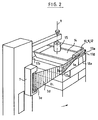
- the latter is applied astride a first corner 17a of the load 2 (FIG. 2).
- the middle zone of the initial free end portion 3a is applied to the first corner 17a.
- This application is such that a local plastic deformation of the film is obtained. Indeed, it is applied to the first corner 17a which is projecting and more or less pointed at its end.
- the initial free end portion 3a is applied to the load 2, in particular the first corner 17a, while the film strip 3 is kept under pre-stretched tension.
- the initial middle part 3b-a of the film strip is applied to an additional corner 17b of the load.
- the initial middle part 3b-a is applied to the three other successive corners 17b, 17c, 17d of the load 2.
- downstream section 3a-c of the initial free end portion 3a is applied to the first corner 17a.
- the initial free end part 3a is twisted, in particular the upstream section 3a-b before applying it to the load 2, in particular by approximately 90 °.
- the initial free end portion 3a of the film strip 3 is therefore applied in part to the end face 13a of the load, in part to its lateral faces 1a, 1b.
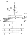
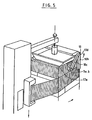
- the upstream section 3a-b is left free. Subsequently, it is covered with the middle part 3b. To this end, the retaining clamp 10 is partially opened and the film section 3a-b is folded down by the internal jaw 10c onto the first layer of film trapping the corners 17d and 17a. The maintenance of the initial free end portion 3a is stopped after at least half a turn and before one turn of the support table 6.
- the initial free end 3a-a is kept axially offset with respect to the film reel 4. Also, at least initially, the free end 3a-a is kept inclined - in particular at least substantially orthogonally - with respect to to the axis 8 of the film reel 4.
- the initial free end 3a-a is kept offset from the zone to be covered by the reference lateral face 1a of the load, that is to say the face from which the holding is carried out. of the film.
- the initial free end 3a-a is maintained at least substantially parallel to or slightly inclined relative to the edge 18a defined by the lateral face la and the end face 13a.
- the initial free end 3a-a is maintained above the upper end face 13a.
- the first corner 17a is preferably an upper corner of the load 2.
- a double helical wrapping is applied. This comprises a first descending interior helical wrapping, then a second exterior ascending helical wrapping.
- the initial free end part 3a of the film strip 3 is associated with the load 2 because the first projecting corner 17a sufficiently deforms the film which is stretched and twisted so that the film is pressed against the first corner 17a and cannot be released from it.
- the holding jaws 10 are, 'at least in the closed holding position, offset axially relative to the film reel 4. In this position, the holding jaws 10 extend in an inclined direction - at least substantially orthogonally - relative to the axis 8 of the coil 4.
- the holding jaws 10 are at least partially offset axially with respect to the film reel 4.
- the holding jaws 10 are released from the film so that the film strip 3 does not do not come to substantially cover the jaws 10.
- the jaws 10 are offset vertically with respect to the area to be covered with the reference lateral face 1a so as not to be located facing it.
- the jaws 10 extend in a direction at least substantially parallel to or slightly inclined relative to the edge 18a. Consequently, the holding jaws 10 in the closed position extend in a direction at least substantially parallel or slightly inclined relative to the longitudinal direction of the film strip 3 covering the load.
- the holding jaws 10, in the closed position, on the one hand, are offset with respect to the reference lateral face la and, on the other hand, extend at least substantially parallel and close to an end face 13a.
- the jaws 10, in the closed position extend in an at least substantially horizontal direction and above the upper end face 13a. This is why the holding jaws 10 are preferably carried by the presser 14.
- the articulation axis 10a of the holding jaws 10 is located on the side which deviates from the coil 4.
- the holding jaws 10 are associated, on the one hand, with first drive means allowing the jaws to be opened and closed, and, on the other hand, with second drive means, separate or not from the first means of drive, allowing the jaws to pivot together around their articulation axis 10a.
- the drive means are housed in a casing placed on the upper face of the presser 14.
- the first and second drive means are constituted by electric, pneumatic or other motors.
- the cross-cutting means 11, on the one hand, and the means for securing the film 12, on the other hand, are preferably carried by the holding jaws 10. This is made possible even with a larger size of the holding jaws 10, since these do not have to be housed between two successive layers of the film strip 3.
- the cross-cutting means consist of teeth carried by one of the jaws, cooperating with an opposite recess carried by the other jaw.
- the means for securing the film 12 comprise means for applying the film to itself (variant shown) such as a flap, fringes, a roller or heat sealing means with electric or magnetic control.
- the support means 7 of the film reel 4 remaining fixed, the table 6 is rotated about the axis 9, thanks to the drive means, the jaws 10 remaining closed and the pre-stretching device used.
- the upstream section 3a-b of the film strip 3 extends between the jaws 10 and the first corner 17a with which the strip 3 interferes. This interference necessarily occurs, due to the offset existing between the jaws 10 and the coil 4.
- the upstream section 3a-b is twisted, which promotes the maintenance of the film on the load 2.
- the upstream section 3a-b is a sufficient length so that the first corner 17a is sufficiently spaced from the free end 3a-a. This is why, the axis 10a is preferably placed in the vicinity of an anal of the presser 14.
- the first corner 17a interfering with the film strip 3 comes to deform it locally, the film being firmly applied to the load 2 around the corner 17a ( Figure 2).
- the downstream section 3a-c and the initial middle part 3b-a are covered.
- the holding jaws 10 are then opened to release the free end 3a-a, therefore the initial free end part 3a.
- the upstream section 3a-b not yet covered by the strip of film trapping the corners 17d-17a is folded over the first layer, and this by means of the inner jaw 10c, the clamp 10 being partially open.
- the outer jaw 10b is held vertically and downward, while the inner jaw 10c is pivoted upward, horizontally.
- the overall movement of the jaw 10 down makes it possible to bring down an upstream section 3a-b (FIG. 5).
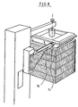
- the clamp 10 is immediately closed in a horizontal position.
- the film reel 4 is again in its original position and the jaws 10b-c placed on either side of the film strip 3. They are then closed. They are placed vertically (FIG. 7) ensuring the cutting of the film on the load side and the maintenance on the reel side.
- the end free end portion 3c of the film can be applied to the middle part 3b for a view. to secure the connection (self-adhesive film for example). This is optionally carried out by additional heat-sealing members 19- or other means of securing (non-sticky film).
Landscapes
- Engineering & Computer Science (AREA)
- Mechanical Engineering (AREA)
- Basic Packing Technique (AREA)
- Lining Or Joining Of Plastics Or The Like (AREA)
- Vehicle Interior And Exterior Ornaments, Soundproofing, And Insulation (AREA)
- Packaging Of Machine Parts And Wound Products (AREA)
- Laminated Bodies (AREA)
Claims (15)
Priority Applications (1)
| Application Number | Priority Date | Filing Date | Title |
|---|---|---|---|
| AT85402068T ATE34714T1 (de) | 1984-10-25 | 1985-10-25 | Verfahren und maschine zum umhuellen der seiten einer last mit einer bahn aus kunststoffolie. |
Applications Claiming Priority (2)
| Application Number | Priority Date | Filing Date | Title |
|---|---|---|---|
| FR8416341 | 1984-10-25 | ||
| FR8416341A FR2572359B1 (fr) | 1984-10-25 | 1984-10-25 | Procede et machine pour recouvrir les faces laterales d'une charge avec une bande de film en matiere plastique |
Publications (3)
| Publication Number | Publication Date |
|---|---|
| EP0180517A1 EP0180517A1 (de) | 1986-05-07 |
| EP0180517B1 EP0180517B1 (de) | 1988-06-01 |
| EP0180517B2 true EP0180517B2 (de) | 1991-12-11 |
Family
ID=9308996
Family Applications (1)
| Application Number | Title | Priority Date | Filing Date |
|---|---|---|---|
| EP85402068A Expired - Lifetime EP0180517B2 (de) | 1984-10-25 | 1985-10-25 | Verfahren und Maschine zum Umhüllen der Seiten einer Last mit einer Bahn aus Kunststoffolie |
Country Status (4)
| Country | Link |
|---|---|
| EP (1) | EP0180517B2 (de) |
| AT (1) | ATE34714T1 (de) |
| DE (1) | DE3563021D1 (de) |
| FR (1) | FR2572359B1 (de) |
Families Citing this family (18)
| Publication number | Priority date | Publication date | Assignee | Title |
|---|---|---|---|---|
| EP0279871A1 (de) * | 1987-02-21 | 1988-08-31 | Cyklop International Ag | Maschine zum Umwickeln von Packgut mit einer Streckfolienbahn |
| ES2008368A6 (es) * | 1987-11-05 | 1989-07-16 | Agfer S A | Maquina enfardadora automatica. |
| WO1989009727A1 (fr) * | 1988-04-06 | 1989-10-19 | Ryozo Matsumoto | Appareil d'emballage pour enroulement d'un film tendu au prealable |
| FR2639906B1 (fr) * | 1988-12-05 | 1991-02-08 | Lin Pac France Sa | Procede et dispositif pour fixer le debut du film sur le plateau rotatif d'une machine pour l'emballage automatique de palettes |
| FI83193C (fi) * | 1989-04-14 | 1991-06-10 | Newtec Int | Foerfarande och anordning foer fogning och avskaerning av vecklingsfilm. |
| FR2650556B1 (fr) * | 1989-08-02 | 1991-12-13 | Newtec Int | Procede et machine de banderolage d'une charge palettisee |
| FR2650555B1 (fr) * | 1989-08-02 | 1991-12-13 | Newtec Int | Procede et machine pour deposer une bande de film de facon helicoidale sur les faces verticales d'une charge palettisee |
| US5203136A (en) * | 1989-09-06 | 1993-04-20 | Newtec International (Societe Anonyme) | Film unwinding carriage for a packaging machine |
| FR2664565B1 (fr) * | 1990-07-16 | 1994-05-13 | Newtec International | Procede et machine d'emballage de la face laterale et d'une face d'extremite d'une charge. |
| FR2669002B1 (fr) * | 1990-11-09 | 1994-10-28 | Newtec Int | Procede, machine et installation d'emballage d'une charge pourvue au moins une corniere de protection d'arete; dispositif de saisie, deplacement, depot et maintien d'une telle corniere. |
| FI93711C (fi) * | 1993-11-29 | 1995-05-26 | Vesme Systems Oy | Menetelmä kulmikkaan esineen käärimiseksi |
| FR2847554B1 (fr) * | 2002-11-25 | 2006-02-10 | Thimon | Machine d'emballage par banderolage d'une charge au moyen d'un film en matiere plastique |
| CA2601562A1 (en) * | 2004-11-03 | 2006-08-17 | Cousins Packaging Inc. | Stretch wrap machine with top corner film transfer |
| US7775016B2 (en) | 2004-11-03 | 2010-08-17 | Cousins Neil G | Stretch wrap machine with top corner film transfer |
| CN106927075A (zh) * | 2017-02-20 | 2017-07-07 | 滁州昭阳电信通讯设备科技有限公司 | 一种外壳带刺水果的自动包裹设备 |
| CN111762363A (zh) * | 2020-07-08 | 2020-10-13 | 海宁先锋印刷有限公司 | 一种基于机械手的薄膜包装装置 |
| DE102021100440A1 (de) | 2021-01-12 | 2022-07-14 | Sina Voss | Verfahren und Vorrichtung zur Ausgabe einer Folienbahn für Packgut |
| CN112977916B (zh) * | 2021-05-06 | 2022-04-19 | 郑州轻工业大学 | 自行走式缠绕包装机器人及物品绕包方法 |
Family Cites Families (6)
| Publication number | Priority date | Publication date | Assignee | Title |
|---|---|---|---|---|
| US4152879A (en) * | 1977-06-21 | 1979-05-08 | Shulman Michael H | Spiral-wrap apparatus |
| US4206846A (en) * | 1977-10-11 | 1980-06-10 | Bemis Company, Inc. | Pallet load wrapping with stretchable plastic netting |
| US4216640A (en) * | 1978-06-12 | 1980-08-12 | Kaufman Charles R | Unit load wrapping machine |
| FR2470055A1 (fr) * | 1979-11-21 | 1981-05-29 | Raffinage Cie Francaise | Procede d'emballage d'un groupement d'articles et charge emballee par ledit procede |
| US4468915A (en) * | 1981-11-30 | 1984-09-04 | Parry John C | Satellite packaging system |
| DE3236029C1 (de) * | 1982-09-29 | 1983-12-29 | C. Keller GmbH u. Co KG, 4530 Ibbenbüren | Vorrichtung zum Einwickeln eines von einer Palette getragenen Stapels in eine Bahn aus Kunststoffolie |
-
1984
- 1984-10-25 FR FR8416341A patent/FR2572359B1/fr not_active Expired
-
1985
- 1985-10-25 EP EP85402068A patent/EP0180517B2/de not_active Expired - Lifetime
- 1985-10-25 DE DE8585402068T patent/DE3563021D1/de not_active Expired
- 1985-10-25 AT AT85402068T patent/ATE34714T1/de not_active IP Right Cessation
Also Published As
| Publication number | Publication date |
|---|---|
| EP0180517B1 (de) | 1988-06-01 |
| ATE34714T1 (de) | 1988-06-15 |
| FR2572359A1 (fr) | 1986-05-02 |
| FR2572359B1 (fr) | 1987-09-25 |
| DE3563021D1 (en) | 1988-07-07 |
| EP0180517A1 (de) | 1986-05-07 |
Similar Documents
| Publication | Publication Date | Title |
|---|---|---|
| EP0180517B2 (de) | Verfahren und Maschine zum Umhüllen der Seiten einer Last mit einer Bahn aus Kunststoffolie | |
| EP0467729B1 (de) | Verfahren und Maschine zum Verpacken der Seitenflächen und einer Endfläche einer Ladung | |
| EP0392933B1 (de) | Verfahren und Vorrichtung zum Schneiden und Schweissen einer Verpackungsfolie | |
| EP0419299B1 (de) | Wagen zum Abwickeln von einem Film zu einer Verpackungsmaschine | |
| EP0522928B1 (de) | Verfahren und Vorrichtungen zum Verpacken von Längsseiten und der Oberseite einer Palettenladung | |
| EP0340102B1 (de) | Vorrichtung zum Aufwickeln von fadenförmigem Material auf einen Wickeldorn beliebiger Form und dieselbe verwendende Aufwickelmaschine | |
| FR2617123A1 (fr) | Bande avec renfort longitudinal, procede d'emballage et emballage comportant une telle bande, installation et machine pour la mise en oeuvre du procede d'emballage, et dispositif pour la realisation d'une telle bande | |
| EP0630813A1 (de) | Vorrichtung zum Handhaben und Halten des freien Endes einer Folie in einer Folien-Einwickelmaschine | |
| EP0875476A1 (de) | Wickler mit zwei Spindeln zum Aufwickeln einer Bahn | |
| CH675104A5 (de) | ||
| FR3012428A1 (fr) | Procede et dispositif de fixation pour fixer une extremite d'une bande de film d'emballage dans une machine d'emballage, et machine d'emballage | |
| EP0015223A1 (de) | Vorrichtung zum Binden von Drahtspulen | |
| EP2206651A1 (de) | Verfahren und Vorrichtung zum Zusammenfügen einer Vielzahl von Dachziegeln | |
| FR2511649A1 (fr) | Procede et appareil permettant d'envelopper la circonference exterieure d'une bobine de tole metallique mince | |
| EP1763471B1 (de) | Verfahren zur umwicklung einer palettierten ladung unter schliessen der oberseite dieser ladung und entsprechendens umwicklungsverfahren | |
| FR2847554A1 (fr) | Machine d'emballage par banderolage d'une charge au moyen d'un film en matiere plastique | |
| FR2697797A1 (fr) | Machine à cercle au ruban adhésif de toute nature. | |
| EP0500433B1 (de) | Verfahren und Vorrichtung zum Befestigen des Fadenendes einer Spule | |
| FR2639611A1 (fr) | Dispositif de pose de coiffe sur une charge emballee par banderolage | |
| EP1419966B1 (de) | Verfahren und Vorrichtung zum Umhüllen einer palettisierten Ladung mit einer Stretchfolienhaube | |
| FR2573059A1 (fr) | Appareil de devidage de film d'emballage | |
| FR2639625A1 (fr) | Dispositif pour l'enrubannage de bobines ou de barres par un ruban isolant ou non | |
| FR2858295A1 (fr) | Banderoleuse et procede de banderolage mis en oeuvre par la banderoleuse | |
| EP1464216A1 (de) | Verfahren zum Umwickeln von Silageballen | |
| FR2673817A3 (fr) | Feuille pour masquer des cheveux a permanenter. |
Legal Events
| Date | Code | Title | Description |
|---|---|---|---|
| PUAI | Public reference made under article 153(3) epc to a published international application that has entered the european phase |
Free format text: ORIGINAL CODE: 0009012 |
|
| AK | Designated contracting states |
Kind code of ref document: A1 Designated state(s): AT CH DE GB IT LI NL SE |
|
| 17P | Request for examination filed |
Effective date: 19860430 |
|
| 17Q | First examination report despatched |
Effective date: 19861023 |
|
| D17Q | First examination report despatched (deleted) | ||
| GRAA | (expected) grant |
Free format text: ORIGINAL CODE: 0009210 |
|
| ITF | It: translation for a ep patent filed | ||
| AK | Designated contracting states |
Kind code of ref document: B1 Designated state(s): AT CH DE GB IT LI NL SE |
|
| PG25 | Lapsed in a contracting state [announced via postgrant information from national office to epo] |
Ref country code: NL Effective date: 19880601 Ref country code: AT Effective date: 19880601 |
|
| REF | Corresponds to: |
Ref document number: 34714 Country of ref document: AT Date of ref document: 19880615 Kind code of ref document: T |
|
| PG25 | Lapsed in a contracting state [announced via postgrant information from national office to epo] |
Ref country code: SE Effective date: 19880630 |
|
| REF | Corresponds to: |
Ref document number: 3563021 Country of ref document: DE Date of ref document: 19880707 |
|
| GBT | Gb: translation of ep patent filed (gb section 77(6)(a)/1977) | ||
| PG25 | Lapsed in a contracting state [announced via postgrant information from national office to epo] |
Ref country code: LI Effective date: 19881031 Ref country code: CH Effective date: 19881031 |
|
| NLV1 | Nl: lapsed or annulled due to failure to fulfill the requirements of art. 29p and 29m of the patents act | ||
| PLBI | Opposition filed |
Free format text: ORIGINAL CODE: 0009260 |
|
| 26 | Opposition filed |
Opponent name: AGFER S.A. Effective date: 19890227 |
|
| REG | Reference to a national code |
Ref country code: CH Ref legal event code: PL |
|
| ITTA | It: last paid annual fee | ||
| PUAH | Patent maintained in amended form |
Free format text: ORIGINAL CODE: 0009272 |
|
| STAA | Information on the status of an ep patent application or granted ep patent |
Free format text: STATUS: PATENT MAINTAINED AS AMENDED |
|
| 27A | Patent maintained in amended form |
Effective date: 19911211 |
|
| AK | Designated contracting states |
Kind code of ref document: B2 Designated state(s): AT CH DE GB IT LI NL SE |
|
| GBTA | Gb: translation of amended ep patent filed (gb section 77(6)(b)/1977) | ||
| PGFP | Annual fee paid to national office [announced via postgrant information from national office to epo] |
Ref country code: DE Payment date: 20001003 Year of fee payment: 16 |
|
| PGFP | Annual fee paid to national office [announced via postgrant information from national office to epo] |
Ref country code: GB Payment date: 20001004 Year of fee payment: 16 |
|
| PG25 | Lapsed in a contracting state [announced via postgrant information from national office to epo] |
Ref country code: GB Free format text: LAPSE BECAUSE OF NON-PAYMENT OF DUE FEES Effective date: 20011025 |
|
| REG | Reference to a national code |
Ref country code: GB Ref legal event code: IF02 |
|
| GBPC | Gb: european patent ceased through non-payment of renewal fee |
Effective date: 20011025 |
|
| PG25 | Lapsed in a contracting state [announced via postgrant information from national office to epo] |
Ref country code: DE Free format text: LAPSE BECAUSE OF NON-PAYMENT OF DUE FEES Effective date: 20020702 |