EP0180528A2 - Verfahren zur medizinischen Analyse einer flüssigen Probe mittels mindestens eines flüssigen Reagenzes und Vorrichtung zur Durchführung des Verfahrens - Google Patents
Verfahren zur medizinischen Analyse einer flüssigen Probe mittels mindestens eines flüssigen Reagenzes und Vorrichtung zur Durchführung des Verfahrens Download PDFInfo
- Publication number
- EP0180528A2 EP0180528A2 EP85420183A EP85420183A EP0180528A2 EP 0180528 A2 EP0180528 A2 EP 0180528A2 EP 85420183 A EP85420183 A EP 85420183A EP 85420183 A EP85420183 A EP 85420183A EP 0180528 A2 EP0180528 A2 EP 0180528A2
- Authority
- EP
- European Patent Office
- Prior art keywords
- weir
- sample
- capillary
- liquid
- reagent
- Prior art date
- Legal status (The legal status is an assumption and is not a legal conclusion. Google has not performed a legal analysis and makes no representation as to the accuracy of the status listed.)
- Withdrawn
Links
Images


Classifications
-
- G—PHYSICS
- G01—MEASURING; TESTING
- G01N—INVESTIGATING OR ANALYSING MATERIALS BY DETERMINING THEIR CHEMICAL OR PHYSICAL PROPERTIES
- G01N21/00—Investigating or analysing materials by the use of optical means, i.e. using sub-millimetre waves, infrared, visible or ultraviolet light
- G01N21/01—Arrangements or apparatus for facilitating the optical investigation
- G01N21/03—Cuvette constructions
- G01N21/07—Centrifugal type cuvettes
-
- Y—GENERAL TAGGING OF NEW TECHNOLOGICAL DEVELOPMENTS; GENERAL TAGGING OF CROSS-SECTIONAL TECHNOLOGIES SPANNING OVER SEVERAL SECTIONS OF THE IPC; TECHNICAL SUBJECTS COVERED BY FORMER USPC CROSS-REFERENCE ART COLLECTIONS [XRACs] AND DIGESTS
- Y10—TECHNICAL SUBJECTS COVERED BY FORMER USPC
- Y10T—TECHNICAL SUBJECTS COVERED BY FORMER US CLASSIFICATION
- Y10T436/00—Chemistry: analytical and immunological testing
- Y10T436/11—Automated chemical analysis
- Y10T436/111666—Utilizing a centrifuge or compartmented rotor
-
- Y—GENERAL TAGGING OF NEW TECHNOLOGICAL DEVELOPMENTS; GENERAL TAGGING OF CROSS-SECTIONAL TECHNOLOGIES SPANNING OVER SEVERAL SECTIONS OF THE IPC; TECHNICAL SUBJECTS COVERED BY FORMER USPC CROSS-REFERENCE ART COLLECTIONS [XRACs] AND DIGESTS
- Y10—TECHNICAL SUBJECTS COVERED BY FORMER USPC
- Y10T—TECHNICAL SUBJECTS COVERED BY FORMER US CLASSIFICATION
- Y10T436/00—Chemistry: analytical and immunological testing
- Y10T436/25—Chemistry: analytical and immunological testing including sample preparation
- Y10T436/25625—Dilution
-
- Y—GENERAL TAGGING OF NEW TECHNOLOGICAL DEVELOPMENTS; GENERAL TAGGING OF CROSS-SECTIONAL TECHNOLOGIES SPANNING OVER SEVERAL SECTIONS OF THE IPC; TECHNICAL SUBJECTS COVERED BY FORMER USPC CROSS-REFERENCE ART COLLECTIONS [XRACs] AND DIGESTS
- Y10—TECHNICAL SUBJECTS COVERED BY FORMER USPC
- Y10T—TECHNICAL SUBJECTS COVERED BY FORMER US CLASSIFICATION
- Y10T436/00—Chemistry: analytical and immunological testing
- Y10T436/25—Chemistry: analytical and immunological testing including sample preparation
- Y10T436/2575—Volumetric liquid transfer
Definitions
- the present invention relates to a method for carrying out medical analysis of a liquid sample of at least one liquid reagent.
- the present invention aims to implement a method for analyzing a very low dose of liquid sample, of the order of a few microliters. This is particularly interesting in the case of medical analyzes because it becomes possible, for example, to avoid patients having to undergo blood tests by means of syringes, and to simply use a few drops of blood collected after a finger.
- Means are provided for positioning said box on the plate of a centrifuge according to several determined positions deduced from one another by a rotation of the box on itself, relative to the plate at a given angle.
- said determined positions of the case are deduced from each other by rotations of the order of 90 and 180 °, corresponding substantially to the angles which said capillary conduits make between them ending in said spillway.
- the capillary conduits have diameters of the order of two tenths of a millimeter.
- the case is closed by a plastic cover provided with a sample storage receptacle communicating directly with said sample storage chamber and located above it.
- the cover also has a chimney located above said overflow and intended to receive a plug capable of closing all the orifices opening into said overflow.
- This chimney as well as said receptacle constitute with the cover a unitary plastic part, the assembly having come from molding.
- the capillary conduits connecting said calibrated cell and a reagent storage chamber with the weir are parallel to each other.
- the capillary conduits connecting two other reagent storage chambers with the weir are diametrically opposite with respect to the weir and form an angle substantially equal to 90 ° with the two aforementioned capillary conduits.
- Said overflow advantageously comprises internal ribs forming deflectors making it possible to prevent a reagent expelled from a storage chamber from entering another storage chamber.
- Figures 1 and 2 show that the upper part of the cover (2) carries a storage receptacle (3) for a liquid sample communicating directly with a sample storage chamber (4) inside the housing.
- the storage chamber (4) is connected by a capillary conduit (5) to a calibrated cell (6) communicating by a capillary conduit (7) with an overflow chamber (8), and by a capillary conduit (10) with a weir (20).
- the latter provided with deflecting ribs (21) and (22), communicates with an analysis tank (11) at the level of the upper part of a common wall (23).
- a fourth reagent storage chamber formed by two cells (60) and (62), communicating with each other through an orifice (63); only the cell (60) communicates with the weir (20) via a capillary conduit (61).
- the latter has a direction substantially at an angle of 45 ° with the conduits (10,31,41,51).
- the cover (2) carries above the weir (20) a chimney (12) capable of receiving a plug (13).
- the stopper (13) has the function of closing all the orifices opening into the outlet (20) (capillary conduits 31, 41, 51, 61 in particular).
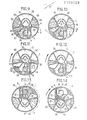
- Figures 9 to 20 show a top view of the device of Figures 1 to 8 during the implementation of the method according to the invention.
- FIG. 9 illustrates the initial phase, when the chambers (30, 40, 50, 60 and 62) of the housing (1) have received reagents (35, 45, 55, 65 respectively).
- the center of rotation of the plate is located so that the end of the cell (6) corresponding to the capillary duct (7) is further away from it than the end corresponding to the capillary duct (10).
- the direction of the centrifugal force is substantially that of the capillary conduits (10) and (31).
- the stopper (13) is removed and a drop of sample (15) of a few microliters is introduced into the receptacle (3).
- the sample (15) ends up in the storage chamber (4) (see Figure 10).
- a first centrifugation is then carried out, an intermediate phase (FIG. 11) and the final phase (FIG. 12) having been illustrated.
- the reagents remain stored in their respective chambers but the sample (15) passes through the calibrated cell (6) and the capillary conduit (7).
- the calibrated cell (6) is filled with sample (15), the excess ends up in the overflow chamber (8).
- a second centrifugation is carried out (see Figures 14 and 15); the sample (15) passes through the capillary conduit (10) in the tank (20) then in the analysis tank (11). Simultaneously the reagent (35) passes through the capillary conduit (31) in the weir (20) and the tank (11). Orientation to centrifugal force capillary conduits (41,51,61) is such that the other reagents remain trapped in their respective storage chambers.
- Figure 15 shows the housing at rest after the second centrifugation: the cell (6) and the reservoir (30) are empty.
- the first centrifugation Figures 11,12
- a final 90 ° rotation of the housing (1) is made around its axis and placing the capillary duct (51) in such a way that a fifth centrifugation allows the reagent (55) to be chased towards the tank (11) where the mixture (100) is then obtained.
- reaction which has appeared in this mixture can be observed by any suitable means.
Landscapes
- Physics & Mathematics (AREA)
- Health & Medical Sciences (AREA)
- Life Sciences & Earth Sciences (AREA)
- Chemical & Material Sciences (AREA)
- Analytical Chemistry (AREA)
- Biochemistry (AREA)
- General Health & Medical Sciences (AREA)
- General Physics & Mathematics (AREA)
- Immunology (AREA)
- Pathology (AREA)
- Investigating Or Analysing Biological Materials (AREA)
- Sampling And Sample Adjustment (AREA)
- Automatic Analysis And Handling Materials Therefor (AREA)
Applications Claiming Priority (2)
| Application Number | Priority Date | Filing Date | Title |
|---|---|---|---|
| FR8416447 | 1984-10-26 | ||
| FR8416447A FR2572533B1 (fr) | 1984-10-26 | 1984-10-26 | Procede destine a realiser l'analyse medicale d'un echantillon liquide a l'aide d'au moins un reactif liquide et dispositif pour la mise en oeuvre du procede |
Publications (2)
| Publication Number | Publication Date |
|---|---|
| EP0180528A2 true EP0180528A2 (de) | 1986-05-07 |
| EP0180528A3 EP0180528A3 (de) | 1987-05-27 |
Family
ID=9309044
Family Applications (1)
| Application Number | Title | Priority Date | Filing Date |
|---|---|---|---|
| EP85420183A Withdrawn EP0180528A3 (de) | 1984-10-26 | 1985-10-18 | Verfahren zur medizinischen Analyse einer flüssigen Probe mittels mindestens eines flüssigen Reagenzes und Vorrichtung zur Durchführung des Verfahrens |
Country Status (7)
| Country | Link |
|---|---|
| US (1) | US4743558A (de) |
| EP (1) | EP0180528A3 (de) |
| JP (1) | JPS61108968A (de) |
| CN (1) | CN85107716A (de) |
| BR (1) | BR8505342A (de) |
| FR (1) | FR2572533B1 (de) |
| IL (1) | IL76824A0 (de) |
Cited By (2)
| Publication number | Priority date | Publication date | Assignee | Title |
|---|---|---|---|---|
| FR2600775A1 (fr) * | 1986-06-26 | 1987-12-31 | Kis Photo Ind | Dispositif d'analyse biomedicale |
| FR2671629A1 (fr) * | 1991-01-10 | 1992-07-17 | Kis Photo Ind | Dispositif d'analyse d'un echantillon liquide. |
Families Citing this family (36)
| Publication number | Priority date | Publication date | Assignee | Title |
|---|---|---|---|---|
| US4892708A (en) * | 1987-07-01 | 1990-01-09 | Miles Inc. | Fluid separation and processing device |
| US5173262A (en) * | 1987-07-17 | 1992-12-22 | Martin Marietta Energy Systems, Inc. | Rotor assembly and method for automatically processing liquids |
| US4835106A (en) * | 1987-07-17 | 1989-05-30 | Martin Marietta Energy Systems, Inc. | Rotor for processing liquids using movable capillary tubes |
| US5242803A (en) * | 1987-07-17 | 1993-09-07 | Martin Marietta Energy Systems, Inc. | Rotor assembly and assay method |
| US5160702A (en) * | 1989-01-17 | 1992-11-03 | Molecular Devices Corporation | Analyzer with improved rotor structure |
| US5326165A (en) * | 1991-06-26 | 1994-07-05 | Irvine Scientific Sales Co. | Mixing apparatus |
| US5304348A (en) * | 1992-02-11 | 1994-04-19 | Abaxis, Inc. | Reagent container for analytical rotor |
| US5591643A (en) * | 1993-09-01 | 1997-01-07 | Abaxis, Inc. | Simplified inlet channels |
| US6235531B1 (en) * | 1993-09-01 | 2001-05-22 | Abaxis, Inc. | Modified siphons for improved metering precision |
| CA2192196C (en) * | 1994-06-06 | 2004-11-23 | Anne R. Kopf-Sill | Modified siphons for improved metering precision |
| WO2002062482A2 (en) * | 2000-11-02 | 2002-08-15 | Gambro, Inc. | Fluid separation devices, systems and methods |
| US6937323B2 (en) * | 2000-11-08 | 2005-08-30 | Burstein Technologies, Inc. | Interactive system for analyzing biological samples and processing related information and the use thereof |
| WO2002044695A1 (en) * | 2000-11-16 | 2002-06-06 | Burstein Technologies, Inc. | Methods and apparatus for detecting and quantifying lymphocytes with optical biodiscs |
| WO2002043866A2 (en) * | 2000-12-01 | 2002-06-06 | Burstein Technologies, Inc. | Apparatus and methods for separating components of particulate suspension |
| US6760298B2 (en) * | 2000-12-08 | 2004-07-06 | Nagaoka & Co., Ltd. | Multiple data layer optical discs for detecting analytes |
| AU2002239554A1 (en) * | 2000-12-08 | 2002-06-18 | Burstein Technologies, Inc. | Optical disc assemblies for performing assays |
| WO2004010099A2 (en) * | 2001-05-16 | 2004-01-29 | Burstein Technologies, Inc. | Variable sampling for rendering pixelization of analysis results in optical bio-disc assembly |
| US20040226348A1 (en) * | 2001-07-24 | 2004-11-18 | Phillip Bruce | Magnetic assisted detection of magnetic beads using optical disc drives |
| WO2003027723A2 (en) * | 2001-07-24 | 2003-04-03 | Burstein Technologies, Inc. | Method and apparatus for bonded fluidic circuit for optical bio-disc |
| US20030129665A1 (en) * | 2001-08-30 | 2003-07-10 | Selvan Gowri Pyapali | Methods for qualitative and quantitative analysis of cells and related optical bio-disc systems |
| US20030143637A1 (en) * | 2001-08-31 | 2003-07-31 | Selvan Gowri Pyapali | Capture layer assemblies for cellular assays including related optical analysis discs and methods |
| AU2002335715A1 (en) * | 2001-09-07 | 2003-03-24 | Burstein Technologies, Inc. | Optical bio-disc systems for nuclear morphology based identification |
| AU2002352735A1 (en) * | 2001-11-20 | 2003-06-10 | Burstein Technologies, Inc. | Optical bio-discs and microfluidic devices for analysis of cells |
| US20040241381A1 (en) * | 2002-01-31 | 2004-12-02 | Chen Yihfar | Microfluidic structures with circumferential grooves for bonding adhesives and related optical analysis discs |
| WO2003064996A2 (en) * | 2002-01-31 | 2003-08-07 | Burstein Technologies, Inc. | Bio-safe dispenser and optical analysis disc assembly |
| US20050221048A1 (en) * | 2002-01-31 | 2005-10-06 | James Rodney Norton | Manufacturing processes for making optical analysis discs including successive patterning operations and optical discs thereby manufactured |
| US20050037484A1 (en) * | 2003-04-23 | 2005-02-17 | Norbert Staimer | Optical bio-discs including spiral fluidic circuits for performing assays |
| US7390464B2 (en) * | 2003-06-19 | 2008-06-24 | Burstein Technologies, Inc. | Fluidic circuits for sample preparation including bio-discs and methods relating thereto |
| WO2004113871A2 (en) * | 2003-06-19 | 2004-12-29 | Nagaoka & Co., Ltd. | Fluidic circuits for sample preparation including bio-discs and methods relating thereto |
| EP1644184A2 (de) * | 2003-06-27 | 2006-04-12 | Nagaoka & Co., Ltd. | Fluidkreisläufe, verfahren und vorrichtung zur verwendung von vollblutproben in kolorimetrischen analysen |
| JP2007500351A (ja) * | 2003-07-25 | 2007-01-11 | 長岡実業株式会社 | バイオディスクを有するサンプル調製用流体回路及びそれに関連した方法 |
| NZ547175A (en) * | 2003-11-14 | 2009-11-27 | Oakville Hong Kong Co Ltd | Sample collection cup with integrated sample analysis system |
| JP4614992B2 (ja) * | 2007-07-27 | 2011-01-19 | パナソニック株式会社 | 分析用デバイスとこれを使用する分析装置および分析方法 |
| WO2013090407A2 (en) | 2011-12-12 | 2013-06-20 | Step Ahead Innovations, Inc. | Aquatic environment monitoring and dosing systems and apparatuses, and methods and software relating thereto |
| WO2014205230A1 (en) | 2013-06-19 | 2014-12-24 | Step Ahead Innovations Inc. | Aquatic environment water parameter testing systems and methods |
| CN108792258A (zh) * | 2018-05-21 | 2018-11-13 | 南京申友生物技术有限公司 | 一种基因检测用试剂盒 |
Family Cites Families (15)
| Publication number | Priority date | Publication date | Assignee | Title |
|---|---|---|---|---|
| US3211368A (en) * | 1962-11-05 | 1965-10-12 | Giovanni Raccuglia | Method and apparatus for treating liquid mixtures |
| FR2067639A5 (de) * | 1969-11-12 | 1971-08-20 | Guigan Jean | |
| SE384271B (sv) * | 1971-01-07 | 1976-04-26 | J Guigan | Vetskefordelningsanordning for samtidig fordelning av kalibrerade mengder av en vetska till sekundera behallare |
| BE792516A (fr) * | 1971-12-09 | 1973-06-08 | Union Carbide Corp | Procede d'analyse spectrophotometrique rapide |
| US3814582A (en) * | 1972-03-02 | 1974-06-04 | Beckman Instruments Inc | Automated chemical analyser system |
| US3890101A (en) * | 1974-02-15 | 1975-06-17 | Us Energy | Collection ring for use in multiple-sample blood fractionation centrifugal rotors |
| US3951608A (en) * | 1975-01-22 | 1976-04-20 | Ernest Trod | Mixing cuvette and timing turntable for providing reaction mixtures |
| FR2409514A1 (fr) * | 1977-11-17 | 1979-06-15 | Bretaudiere Jean Pierre | Perfectionnement aux appareils d'analyse par centrifugation |
| FR2496268A1 (fr) * | 1980-12-15 | 1982-06-18 | Guigan Jean | Dispositif autonome d'analyse simultanee et procede de mise en oeuvre |
| FR2503866A1 (fr) * | 1981-04-14 | 1982-10-15 | Guigan Jean | Dispositif pour delivrer une dose determinee d'un echantillon de liquide dans une cellule et procede associe |
| FR2519763A1 (fr) * | 1982-01-14 | 1983-07-18 | Guigan Jean | Dispositif de conditionnement pour analyses multiples |
| FR2524874A1 (fr) * | 1982-04-07 | 1983-10-14 | Guigan Jean | Procede et dispositif pour le transfert de faibles doses liquides |
| US4632908A (en) * | 1984-05-03 | 1986-12-30 | Abbott Laboratories | Heating system for rotating members |
| NZ211887A (en) * | 1984-05-03 | 1987-05-29 | Abbott Lab | Sample processor card for use with centrifuge |
| FR2579756B1 (fr) * | 1985-03-26 | 1987-05-07 | Guigan Jean | Procede pour realiser des analyses biologiques utilisant des reactions immunologiques et dispositif de mise en oeuvre |
-
1984
- 1984-10-26 FR FR8416447A patent/FR2572533B1/fr not_active Expired
-
1985
- 1985-10-18 EP EP85420183A patent/EP0180528A3/de not_active Withdrawn
- 1985-10-22 CN CN198585107716A patent/CN85107716A/zh active Pending
- 1985-10-22 US US06/790,011 patent/US4743558A/en not_active Expired - Fee Related
- 1985-10-25 BR BR8505342A patent/BR8505342A/pt unknown
- 1985-10-25 IL IL76824A patent/IL76824A0/xx unknown
- 1985-10-25 JP JP60240345A patent/JPS61108968A/ja active Pending
Cited By (4)
| Publication number | Priority date | Publication date | Assignee | Title |
|---|---|---|---|---|
| FR2600775A1 (fr) * | 1986-06-26 | 1987-12-31 | Kis Photo Ind | Dispositif d'analyse biomedicale |
| EP0251946A1 (de) * | 1986-06-26 | 1988-01-07 | KIS PHOTO INDUSTRIE S.a.r.l. | Vorrichtung zum Analysieren einer flüssigen Probe |
| US4857274A (en) * | 1986-06-26 | 1989-08-15 | Kis Photo Industrie | Device for analyzing a liquid sample |
| FR2671629A1 (fr) * | 1991-01-10 | 1992-07-17 | Kis Photo Ind | Dispositif d'analyse d'un echantillon liquide. |
Also Published As
| Publication number | Publication date |
|---|---|
| CN85107716A (zh) | 1986-07-16 |
| EP0180528A3 (de) | 1987-05-27 |
| JPS61108968A (ja) | 1986-05-27 |
| BR8505342A (pt) | 1986-08-05 |
| US4743558A (en) | 1988-05-10 |
| FR2572533B1 (fr) | 1986-12-26 |
| IL76824A0 (en) | 1986-02-28 |
| FR2572533A1 (fr) | 1986-05-02 |
Similar Documents
| Publication | Publication Date | Title |
|---|---|---|
| EP0180528A2 (de) | Verfahren zur medizinischen Analyse einer flüssigen Probe mittels mindestens eines flüssigen Reagenzes und Vorrichtung zur Durchführung des Verfahrens | |
| EP0183627A2 (de) | Verfahren zur medizinischen Analyse einer flüssigen Probe mittels mindestens eines trockenen Reagenzes und Vorrichtung zur Durchführung des Verfahrens | |
| EP0251946B1 (de) | Vorrichtung zum Analysieren einer flüssigen Probe | |
| EP0197865A1 (de) | Verfahren und Vorrichtung zum Durchführen von biologischen Analysen mittels immunologischen Reaktionen | |
| EP0352689B1 (de) | Vorrichtung für biologische Analysen mittels Enzymimmun-Test von Antikörpern oder Antigenen in einem Serum | |
| EP0230618A1 (de) | Verfahren und Vorrichtung zum Entnehmen einer bestimmten Menge Plasma aus einer Blutprobe für die Analyse | |
| EP0658489B1 (de) | Vorrichtung zum Ausgeben von kugelförmigen Produkten mit denselben Massen, wie z.B. Tabletten | |
| EP0352690B1 (de) | Minilabor zur Durchführung biologischer Analysen mittels einer chemischen Blutprobenreaktion | |
| EP0062907B1 (de) | Verfahren und Vorrichtung zum Übertragen einer bestimmten Menge einer Flüssigkeitsprobe in eine Zelle | |
| EP0469504B1 (de) | Vorrichtung zur Zentrifugaltrennung von zwei Phasen einer heterogenen Flüssigkeit, insbesondere verwendbar zur Trennung von Blutplasma | |
| EP0066828B1 (de) | Vorrichtung und Verfahren um eine Flüssigkeitsprobe nacheinander mit einer Vielheit von Reagenzien in Kontakt zu bringen | |
| EP0197866B1 (de) | Verfahren und Vorrichtung zum Durchführen von klinischen Analysen mittels Trockenreagenzien | |
| FR2484645A1 (fr) | Rotor d'analyse destine notamment a un analyseur de chimie clinique et son utilisation | |
| FR2464100A1 (fr) | Separateur centrifuge a dispositif de debordement | |
| FR2665647A1 (fr) | Flacon pour reactifs chimiques. | |
| CA2072402C (fr) | Dispositif pour prelever et restituer une quantite predeterminee et constante d'un liquide | |
| FR2589240A1 (fr) | Barrette d'analyse monoparametre | |
| FR2505677A1 (fr) | Dispositif pour recueillir et contenir de l'urine destinee a des laboratoires d'analyses | |
| EP4335384A1 (de) | Vorrichtung zur behandlung einer fäkalen materialprobe | |
| WO2009150359A1 (fr) | Dispositif de coloration de lames pour examens au microscope | |
| EP0082778B1 (de) | Kanister und Behältereinheit bestehend aus einem Kanister und einem Flakon | |
| FR2488701A1 (fr) | Cuve de developpement photographique | |
| FR2777807A1 (fr) | Turbine de mise en circulation d'une masse de matiere de viscocite determinee | |
| FR2763566A1 (fr) | Conditionnement pour un liquide visqueux | |
| FR2671629A1 (fr) | Dispositif d'analyse d'un echantillon liquide. |
Legal Events
| Date | Code | Title | Description |
|---|---|---|---|
| PUAI | Public reference made under article 153(3) epc to a published international application that has entered the european phase |
Free format text: ORIGINAL CODE: 0009012 |
|
| AK | Designated contracting states |
Kind code of ref document: A2 Designated state(s): AT BE CH DE GB IT LI LU NL SE |
|
| PUAL | Search report despatched |
Free format text: ORIGINAL CODE: 0009013 |
|
| AK | Designated contracting states |
Kind code of ref document: A3 Designated state(s): AT BE CH DE GB IT LI LU NL SE |
|
| 17P | Request for examination filed |
Effective date: 19871120 |
|
| 17Q | First examination report despatched |
Effective date: 19890711 |
|
| STAA | Information on the status of an ep patent application or granted ep patent |
Free format text: STATUS: THE APPLICATION IS DEEMED TO BE WITHDRAWN |
|
| 18D | Application deemed to be withdrawn |
Effective date: 19900228 |