EP0180533A1 - Ventil und Sammelkanal für die Beheizung eines Kompressorrotors - Google Patents
Ventil und Sammelkanal für die Beheizung eines Kompressorrotors Download PDFInfo
- Publication number
- EP0180533A1 EP0180533A1 EP85630110A EP85630110A EP0180533A1 EP 0180533 A1 EP0180533 A1 EP 0180533A1 EP 85630110 A EP85630110 A EP 85630110A EP 85630110 A EP85630110 A EP 85630110A EP 0180533 A1 EP0180533 A1 EP 0180533A1
- Authority
- EP
- European Patent Office
- Prior art keywords
- valve
- compressor
- bore
- manifold
- air
- Prior art date
- Legal status (The legal status is an assumption and is not a legal conclusion. Google has not performed a legal analysis and makes no representation as to the accuracy of the status listed.)
- Granted
Links
- 238000010438 heat treatment Methods 0.000 title claims description 3
- 125000006850 spacer group Chemical group 0.000 description 3
- 230000006835 compression Effects 0.000 description 2
- 238000007906 compression Methods 0.000 description 2
- 238000007599 discharging Methods 0.000 description 2
- 230000007257 malfunction Effects 0.000 description 2
- 230000002093 peripheral effect Effects 0.000 description 2
- 238000005266 casting Methods 0.000 description 1
- 230000000295 complement effect Effects 0.000 description 1
- 238000005516 engineering process Methods 0.000 description 1
- 239000012530 fluid Substances 0.000 description 1
- 238000000034 method Methods 0.000 description 1
- 238000012986 modification Methods 0.000 description 1
- 230000004048 modification Effects 0.000 description 1
- 230000001105 regulatory effect Effects 0.000 description 1
Images
Classifications
-
- F—MECHANICAL ENGINEERING; LIGHTING; HEATING; WEAPONS; BLASTING
- F01—MACHINES OR ENGINES IN GENERAL; ENGINE PLANTS IN GENERAL; STEAM ENGINES
- F01D—NON-POSITIVE DISPLACEMENT MACHINES OR ENGINES, e.g. STEAM TURBINES
- F01D11/00—Preventing or minimising internal leakage of working-fluid, e.g. between stages
- F01D11/08—Preventing or minimising internal leakage of working-fluid, e.g. between stages for sealing space between rotor blade tips and stator
- F01D11/14—Adjusting or regulating tip-clearance, i.e. distance between rotor-blade tips and stator casing
- F01D11/20—Actively adjusting tip-clearance
- F01D11/24—Actively adjusting tip-clearance by selectively cooling-heating stator or rotor components
-
- Y—GENERAL TAGGING OF NEW TECHNOLOGICAL DEVELOPMENTS; GENERAL TAGGING OF CROSS-SECTIONAL TECHNOLOGIES SPANNING OVER SEVERAL SECTIONS OF THE IPC; TECHNICAL SUBJECTS COVERED BY FORMER USPC CROSS-REFERENCE ART COLLECTIONS [XRACs] AND DIGESTS
- Y02—TECHNOLOGIES OR APPLICATIONS FOR MITIGATION OR ADAPTATION AGAINST CLIMATE CHANGE
- Y02T—CLIMATE CHANGE MITIGATION TECHNOLOGIES RELATED TO TRANSPORTATION
- Y02T50/00—Aeronautics or air transport
- Y02T50/60—Efficient propulsion technologies, e.g. for aircraft
Definitions
- This invention relates to gas turbine engines and particularly to the active clearance control for selectively heating the bore of the compressor to reduce tip clearance.
- a method for reducing clearance between the tips of the blades of an axial flow compressor and its outer air seal is to selectively heat the bore to thermally grow the blades toward the outer air seals which are grounded to the engine case.
- my co-invention for U.S. Patent Application Serial No. 548,466 filed on November 3, 1983 and assigned to the same assignee as this patent application discloses such a system that uses mid-stage compressor air and a downstream stage of hotter air to selectively heat the bore. In this system the air is bled from the compressor through openings in the engine case and is ducted externally to the feed system for admitting the air into the compressor bore.
- the system described above can be simplified by fabricating the engine case to include both the manifold for collecting the air to be admitted into the compressor bore and employing an integral valve adapted to fit a boss formed on the engine case.
- the valve is particularly designed so that it is fail safe in the cooler position rather than the hotter one as will be apparent from the description hereinbelow.
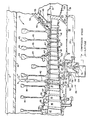
- Fig. is a partial view partly in section and partly in schematic of a turbine type power plant showing the details of this invention.
- FIG. 10 which shows a portion of the high compressor section generally illustrated by reference numeral 10 as consisting of stages of compression comprising rotors having blades 12 and its attendant disks 14 and a plurality of rows of stator vanes 16.
- reference numeral 10 shows a portion of the high compressor section generally illustrated by reference numeral 10 as consisting of stages of compression comprising rotors having blades 12 and its attendant disks 14 and a plurality of rows of stator vanes 16.
- Air is bled from the 9th stage of compression and a higher stage which is the last stage (15th) in this instance.
- the air discharging from the compressor is diffused through a diffuser 21 prior to being fed into the combustor.
- the 15th stage air is bled from the diffuser case 21 through the bleed 33 into the cavity 25 surrounding the diffuser where it is piped out of the engine through the opening 23 in the outer case 31 and the externally mounted conduit 20, and then fed to valve generally illustrated by reference numeral 26.
- air from the 9th stage is bled into the cavity 27 surrounding the compressor inner case 39 through the bleed 32 and conducted to the bore 43 via valve 26 in the manner to be described hereinbelow.
- This bled air is directed into the bore area of the compressor by valve 26 where it is directed radially inward toward the engine centerline A.
- one or more vanes 40 are made hollow and communicate with cavity 28.
- a plurality of anti-vortex tubes 42 are attached to the spacer 47 and rotate therewith and communicate with the flow discharging from the ends of the hollow vanes 40 and terminate in close proximity to shaft 41.
- labyrinth seals 44.and 46 will likewise expand and minimize the gap.
- the knife edge 55 attached to the outer diameter of spacer 47 will be expanded and contracted as a function of the temperature of the bled air fed into the bore area of the compressor and will move toward and away from land 57. (Although certain elements are differently dimensioned, it carries the same reference numeral if its function is the same).
- valve 26 is controlled in any well known manner so that air from the 9th stage is fed to the bore area during high powered engine operation such as takeoff and the 15th stage bled air is connected during a reduced power such as aircraft's cruise condition.
- the higher stage obviously, is at the higher temperature so as to heat the bore area and cause the disks to grow radially outward and close the gap between the tips of the blades and its peripheral seal.
- the labyrinth seals 46 & 44 are likewise heated so as to maintain a minimal gap.
- valve 26 By proper modulation of valve 26 in response to appropriate commands, the temperature and volumetric flow of air can be suitably regulated.
- valve 26 By proper modulation of valve 26 in response to appropriate commands, the temperature and volumetric flow of air can be suitably regulated.
- valve 26 is a two positional valve either communicating the bores 43 of the compressor with 9th stage bleed air or 15th stage bleed air and is made integral with the engine case.
- the engine case is extended radially at the portion indicated by reference numeral 60 and extends circumferentially to define a manifold 62 accommodating the air to be fed to the anti-vortex tube 42.
- Valve housing 64 is mounted with its complementary flanges 66 to the flanges 68 of the boss 70 formed in casing 60.
- Valve 26 comprises a valve element 72 and valve stem 74 suitably supported in valve housing 64 for rectilinear motion.
- the valve stem 7 4 is connected to and actuated as schematically illustrated which responds to output commands to position valve element to seat 76 to block off the high presure 15th stage air (as shown) or to seat 78 circumscribing the circular opening 80 formed in the extension 82 of the inner case 39 to block off 9th stage air.
- valve element 72 To assure that the valve element 72 blocks off the higher presure air in the event of a valve malfunction, the valve element 72 is designed so that a greater area is exposed to 9th stage bleed air than is exposed to 15th stage bleed air. Consequently, in the event of a malfunction, since the area is greater notwithstanding the fact that the 15th stage bleed air is at a higher pressure the valve element 72 will seat on seat 76.
Landscapes
- Engineering & Computer Science (AREA)
- Mechanical Engineering (AREA)
- General Engineering & Computer Science (AREA)
- Structures Of Non-Positive Displacement Pumps (AREA)
- Turbine Rotor Nozzle Sealing (AREA)
Applications Claiming Priority (2)
| Application Number | Priority Date | Filing Date | Title |
|---|---|---|---|
| US06/667,031 US4645416A (en) | 1984-11-01 | 1984-11-01 | Valve and manifold for compressor bore heating |
| US667031 | 2000-09-21 |
Publications (2)
| Publication Number | Publication Date |
|---|---|
| EP0180533A1 true EP0180533A1 (de) | 1986-05-07 |
| EP0180533B1 EP0180533B1 (de) | 1988-06-15 |
Family
ID=24676526
Family Applications (1)
| Application Number | Title | Priority Date | Filing Date |
|---|---|---|---|
| EP85630110A Expired EP0180533B1 (de) | 1984-11-01 | 1985-07-11 | Ventil und Sammelkanal für die Beheizung eines Kompressorrotors |
Country Status (6)
| Country | Link |
|---|---|
| US (1) | US4645416A (de) |
| EP (1) | EP0180533B1 (de) |
| JP (1) | JPS61108809A (de) |
| CA (1) | CA1230059A (de) |
| DE (2) | DE3563369D1 (de) |
| IL (1) | IL75779A (de) |
Cited By (6)
| Publication number | Priority date | Publication date | Assignee | Title |
|---|---|---|---|---|
| GB2217785A (en) * | 1988-04-07 | 1989-11-01 | Gen Electric | Turbomachine rotor temperature control |
| EP1672171A3 (de) * | 2004-12-17 | 2009-09-02 | United Technologies Corporation | Turbinentriebwerks mit gestapeltem Rotor |
| EP1820936A3 (de) * | 2006-02-15 | 2010-12-01 | Rolls-Royce plc | Rotorbelüftungsanordnung für ein Gasturbinentriebwerk |
| EP2995769A1 (de) * | 2014-09-12 | 2016-03-16 | United Technologies Corporation | Wärmeregelungssysteme eines turbomaschinenrotors |
| US9938840B2 (en) | 2015-02-10 | 2018-04-10 | United Technologies Corporation | Stator vane with platform having sloped face |
| US10161250B2 (en) | 2015-02-10 | 2018-12-25 | United Technologies Corporation | Rotor with axial arm having protruding ramp |
Families Citing this family (23)
| Publication number | Priority date | Publication date | Assignee | Title |
|---|---|---|---|---|
| DE3636974A1 (de) * | 1986-10-30 | 1988-05-05 | Bayer Ag | Poly-(ether-urethan-harnstoff)polyadditionsprodukte, ihre herstellung, abmischung enthaltend diese sowie ihre verwendung als abformmassen |
| US4893983A (en) * | 1988-04-07 | 1990-01-16 | General Electric Company | Clearance control system |
| US5088885A (en) * | 1989-10-12 | 1992-02-18 | United Technologies Corporation | Method for protecting gas turbine engine seals |
| US5154048A (en) * | 1990-10-01 | 1992-10-13 | General Electric Company | Apparatus for thrust balancing and frame heating |
| GB9027986D0 (en) * | 1990-12-22 | 1991-02-13 | Rolls Royce Plc | Gas turbine engine clearance control |
| US5472313A (en) * | 1991-10-30 | 1995-12-05 | General Electric Company | Turbine disk cooling system |
| US6267553B1 (en) * | 1999-06-01 | 2001-07-31 | Joseph C. Burge | Gas turbine compressor spool with structural and thermal upgrades |
| US7309210B2 (en) | 2004-12-17 | 2007-12-18 | United Technologies Corporation | Turbine engine rotor stack |
| US8177503B2 (en) * | 2009-04-17 | 2012-05-15 | United Technologies Corporation | Turbine engine rotating cavity anti-vortex cascade |
| US8465252B2 (en) * | 2009-04-17 | 2013-06-18 | United Technologies Corporation | Turbine engine rotating cavity anti-vortex cascade |
| US8540482B2 (en) | 2010-06-07 | 2013-09-24 | United Technologies Corporation | Rotor assembly for gas turbine engine |
| US9145771B2 (en) | 2010-07-28 | 2015-09-29 | United Technologies Corporation | Rotor assembly disk spacer for a gas turbine engine |
| US8662845B2 (en) | 2011-01-11 | 2014-03-04 | United Technologies Corporation | Multi-function heat shield for a gas turbine engine |
| US8840375B2 (en) | 2011-03-21 | 2014-09-23 | United Technologies Corporation | Component lock for a gas turbine engine |
| WO2014055106A1 (en) * | 2012-10-01 | 2014-04-10 | United Technologies Corporation | Gas turbine engine including bleed system coupled to upstream and downstream locations of compressor |
| EP2935804B1 (de) | 2012-12-18 | 2020-04-29 | United Technologies Corporation | Gasturbinenmotor-innengehäuse mit unsymmetrischen entlüftungsschlitzen |
| US10094296B2 (en) | 2013-02-19 | 2018-10-09 | United Technologies Corporation | Gas turbine engine with rotor bore heating |
| US9611752B2 (en) | 2013-03-15 | 2017-04-04 | General Electric Company | Compressor start bleed system for a turbine system and method of controlling a compressor start bleed system |
| EP3058176B1 (de) | 2013-10-02 | 2020-08-26 | United Technologies Corporation | Gasturbinentriebwerk mit verdichterplattendeflektoren |
| US9995222B2 (en) | 2014-07-25 | 2018-06-12 | United Technologies Corporation | High temperature disk conditioning system |
| US10302014B2 (en) | 2015-01-16 | 2019-05-28 | United Technologies Corporation | Modifying a gas turbine engine to use a high pressure compressor as a low pressure compressor |
| US11512594B2 (en) * | 2020-06-05 | 2022-11-29 | General Electric Company | System and method for modulating airflow into a bore of a rotor to control blade tip clearance |
| US12221079B1 (en) | 2023-08-09 | 2025-02-11 | Camco Manufacturing, Llc | Leveling block set |
Citations (7)
| Publication number | Priority date | Publication date | Assignee | Title |
|---|---|---|---|---|
| CH235103A (de) * | 1941-09-05 | 1944-11-15 | Daimler Benz Ag | Verfahren zum Betreiben von mehrstufigen Axialverdichtern und Einrichtung zur Durchführung des Verfahrens. |
| US3452542A (en) * | 1966-09-30 | 1969-07-01 | Gen Electric | Gas turbine engine cooling system |
| US3849020A (en) * | 1973-09-13 | 1974-11-19 | Bendix Corp | Fluidic compressor air bleed valve control apparatus |
| GB2009854A (en) * | 1977-12-13 | 1979-06-20 | Pratt & Whitney Aircraft | Turbine engine with induced pre-swirl at compressor inlet |
| GB2025536A (en) * | 1978-07-17 | 1980-01-23 | Gen Electric | Turbine rotor/shroud clearance control system |
| US4462204A (en) * | 1982-07-23 | 1984-07-31 | General Electric Company | Gas turbine engine cooling airflow modulator |
| EP0141770A1 (de) * | 1983-11-03 | 1985-05-15 | United Technologies Corporation | Aktive Rotorspielregelung |
Family Cites Families (9)
| Publication number | Priority date | Publication date | Assignee | Title |
|---|---|---|---|---|
| US2837270A (en) * | 1952-07-24 | 1958-06-03 | Gen Motors Corp | Axial flow compressor |
| DE1070880B (de) * | 1956-12-19 | 1959-12-10 | Rolls-Royce Limited, Derby (Großbritannien) | Gasturbinenaggregat mit Turboverdichter |
| US3647313A (en) * | 1970-06-01 | 1972-03-07 | Gen Electric | Gas turbine engines with compressor rotor cooling |
| US3844110A (en) * | 1973-02-26 | 1974-10-29 | Gen Electric | Gas turbine engine internal lubricant sump venting and pressurization system |
| US3945759A (en) * | 1974-10-29 | 1976-03-23 | General Electric Company | Bleed air manifold |
| US4268221A (en) * | 1979-03-28 | 1981-05-19 | United Technologies Corporation | Compressor structure adapted for active clearance control |
| US4329114A (en) * | 1979-07-25 | 1982-05-11 | The United States Of America As Represented By The Administrator Of The National Aeronautics And Space Administration | Active clearance control system for a turbomachine |
| GB2108586B (en) * | 1981-11-02 | 1985-08-07 | United Technologies Corp | Gas turbine engine active clearance control |
| US4648241A (en) * | 1983-11-03 | 1987-03-10 | United Technologies Corporation | Active clearance control |
-
1984
- 1984-11-01 US US06/667,031 patent/US4645416A/en not_active Expired - Lifetime
-
1985
- 1985-06-28 CA CA000486044A patent/CA1230059A/en not_active Expired
- 1985-07-11 EP EP85630110A patent/EP0180533B1/de not_active Expired
- 1985-07-11 DE DE8585630110T patent/DE3563369D1/de not_active Expired
- 1985-07-11 DE DE198585630110T patent/DE180533T1/de active Pending
- 1985-07-12 IL IL75779A patent/IL75779A/xx not_active IP Right Cessation
- 1985-07-24 JP JP60163794A patent/JPS61108809A/ja active Granted
Patent Citations (7)
| Publication number | Priority date | Publication date | Assignee | Title |
|---|---|---|---|---|
| CH235103A (de) * | 1941-09-05 | 1944-11-15 | Daimler Benz Ag | Verfahren zum Betreiben von mehrstufigen Axialverdichtern und Einrichtung zur Durchführung des Verfahrens. |
| US3452542A (en) * | 1966-09-30 | 1969-07-01 | Gen Electric | Gas turbine engine cooling system |
| US3849020A (en) * | 1973-09-13 | 1974-11-19 | Bendix Corp | Fluidic compressor air bleed valve control apparatus |
| GB2009854A (en) * | 1977-12-13 | 1979-06-20 | Pratt & Whitney Aircraft | Turbine engine with induced pre-swirl at compressor inlet |
| GB2025536A (en) * | 1978-07-17 | 1980-01-23 | Gen Electric | Turbine rotor/shroud clearance control system |
| US4462204A (en) * | 1982-07-23 | 1984-07-31 | General Electric Company | Gas turbine engine cooling airflow modulator |
| EP0141770A1 (de) * | 1983-11-03 | 1985-05-15 | United Technologies Corporation | Aktive Rotorspielregelung |
Cited By (7)
| Publication number | Priority date | Publication date | Assignee | Title |
|---|---|---|---|---|
| GB2217785A (en) * | 1988-04-07 | 1989-11-01 | Gen Electric | Turbomachine rotor temperature control |
| GB2217785B (en) * | 1988-04-07 | 1992-10-07 | Gen Electric | Turbomachine rotor temperature control. |
| EP1672171A3 (de) * | 2004-12-17 | 2009-09-02 | United Technologies Corporation | Turbinentriebwerks mit gestapeltem Rotor |
| EP1820936A3 (de) * | 2006-02-15 | 2010-12-01 | Rolls-Royce plc | Rotorbelüftungsanordnung für ein Gasturbinentriebwerk |
| EP2995769A1 (de) * | 2014-09-12 | 2016-03-16 | United Technologies Corporation | Wärmeregelungssysteme eines turbomaschinenrotors |
| US9938840B2 (en) | 2015-02-10 | 2018-04-10 | United Technologies Corporation | Stator vane with platform having sloped face |
| US10161250B2 (en) | 2015-02-10 | 2018-12-25 | United Technologies Corporation | Rotor with axial arm having protruding ramp |
Also Published As
| Publication number | Publication date |
|---|---|
| JPH057542B2 (de) | 1993-01-29 |
| IL75779A (en) | 1991-08-16 |
| EP0180533B1 (de) | 1988-06-15 |
| CA1230059A (en) | 1987-12-08 |
| JPS61108809A (ja) | 1986-05-27 |
| US4645416A (en) | 1987-02-24 |
| IL75779A0 (en) | 1985-11-29 |
| DE3563369D1 (en) | 1988-07-21 |
| DE180533T1 (de) | 1986-09-25 |
Similar Documents
| Publication | Publication Date | Title |
|---|---|---|
| US4645416A (en) | Valve and manifold for compressor bore heating | |
| US4576547A (en) | Active clearance control | |
| US11959423B2 (en) | Modulating fuel for a turbine engine | |
| US11092013B2 (en) | Modulated turbine cooling system | |
| US4893984A (en) | Clearance control system | |
| US4487016A (en) | Modulated clearance control for an axial flow rotary machine | |
| US5022817A (en) | Thermostatic control of turbine cooling air | |
| EP2809909B1 (de) | Gasturbinenmotorpuffersystem mit zonenbelüftung | |
| KR960034693A (ko) | 가스 터빈용 압축기 로터 냉각 시스템 | |
| EP0140818B1 (de) | Aktive Rotorspielregelung | |
| CA2042220A1 (en) | Aft entry cooling system and method for an aircraft engine | |
| GB2081392A (en) | Turbomachine seal | |
| JPH0689653B2 (ja) | ガスタービンエンジンの圧縮機用の羽根及びパツキングの隙間最適化装置 | |
| EP3453842B1 (de) | Verteileranordnung zur aktiven spaltsteuerung und zugehöriger gasturbinenmotor | |
| US4804310A (en) | Clearance control apparatus for a bladed fluid flow machine | |
| US11175187B2 (en) | Air temperature sensor having a bushing | |
| JPH0670374B2 (ja) | 航空機エンジンを非航空用エンジンに転換する方法および非航空用エンジン | |
| EP3444464A1 (de) | System und verfahren zum drehen eines gasturbinenmotors während eines motorzyklus | |
| EP3260657B1 (de) | Minischeibe für einen gasturbinenmotor | |
| EP3584412B1 (de) | Thermisch reagierende kühlungsdurchflussmesser für ein gasturbinentriebwerk | |
| CN110939517B (zh) | 包壳主动间隙控制结构 | |
| GB2034415A (en) | Turbine stator mounting | |
| EP3192968B1 (de) | Minischeibe für einen gasturbinenmotor | |
| WO2020106719A2 (en) | Seal assembly for a turbo machine | |
| US20240271542A1 (en) | Low-pressure turbine |
Legal Events
| Date | Code | Title | Description |
|---|---|---|---|
| PUAI | Public reference made under article 153(3) epc to a published international application that has entered the european phase |
Free format text: ORIGINAL CODE: 0009012 |
|
| AK | Designated contracting states |
Kind code of ref document: A1 Designated state(s): DE FR GB IT SE |
|
| ITCL | It: translation for ep claims filed |
Representative=s name: RICCARDI SERGIO & CO. |
|
| 17P | Request for examination filed |
Effective date: 19860505 |
|
| EL | Fr: translation of claims filed | ||
| DET | De: translation of patent claims | ||
| 17Q | First examination report despatched |
Effective date: 19870126 |
|
| GRAA | (expected) grant |
Free format text: ORIGINAL CODE: 0009210 |
|
| AK | Designated contracting states |
Kind code of ref document: B1 Designated state(s): DE FR GB IT SE |
|
| REF | Corresponds to: |
Ref document number: 3563369 Country of ref document: DE Date of ref document: 19880721 |
|
| ET | Fr: translation filed | ||
| ITF | It: translation for a ep patent filed | ||
| PLBE | No opposition filed within time limit |
Free format text: ORIGINAL CODE: 0009261 |
|
| STAA | Information on the status of an ep patent application or granted ep patent |
Free format text: STATUS: NO OPPOSITION FILED WITHIN TIME LIMIT |
|
| 26N | No opposition filed | ||
| ITTA | It: last paid annual fee | ||
| PGFP | Annual fee paid to national office [announced via postgrant information from national office to epo] |
Ref country code: FR Payment date: 19930610 Year of fee payment: 9 |
|
| PGFP | Annual fee paid to national office [announced via postgrant information from national office to epo] |
Ref country code: SE Payment date: 19930615 Year of fee payment: 9 Ref country code: GB Payment date: 19930615 Year of fee payment: 9 |
|
| PGFP | Annual fee paid to national office [announced via postgrant information from national office to epo] |
Ref country code: DE Payment date: 19930621 Year of fee payment: 9 |
|
| PG25 | Lapsed in a contracting state [announced via postgrant information from national office to epo] |
Ref country code: GB Effective date: 19940711 |
|
| PG25 | Lapsed in a contracting state [announced via postgrant information from national office to epo] |
Ref country code: SE Effective date: 19940712 |
|
| EUG | Se: european patent has lapsed |
Ref document number: 85630110.6 Effective date: 19950210 |
|
| GBPC | Gb: european patent ceased through non-payment of renewal fee |
Effective date: 19940711 |
|
| PG25 | Lapsed in a contracting state [announced via postgrant information from national office to epo] |
Ref country code: FR Effective date: 19950331 |
|
| PG25 | Lapsed in a contracting state [announced via postgrant information from national office to epo] |
Ref country code: DE Effective date: 19950401 |
|
| EUG | Se: european patent has lapsed |
Ref document number: 85630110.6 |
|
| REG | Reference to a national code |
Ref country code: FR Ref legal event code: ST |