EP0180537A2 - Interrupteur du type MCCB à deux parts de boîte - Google Patents
Interrupteur du type MCCB à deux parts de boîte Download PDFInfo
- Publication number
- EP0180537A2 EP0180537A2 EP85730127A EP85730127A EP0180537A2 EP 0180537 A2 EP0180537 A2 EP 0180537A2 EP 85730127 A EP85730127 A EP 85730127A EP 85730127 A EP85730127 A EP 85730127A EP 0180537 A2 EP0180537 A2 EP 0180537A2
- Authority
- EP
- European Patent Office
- Prior art keywords
- pole
- circuit breaker
- housing
- housing part
- frame
- Prior art date
- Legal status (The legal status is an assumption and is not a legal conclusion. Google has not performed a legal analysis and makes no representation as to the accuracy of the status listed.)
- Withdrawn
Links
Images



Classifications
-
- H—ELECTRICITY
- H01—ELECTRIC ELEMENTS
- H01H—ELECTRIC SWITCHES; RELAYS; SELECTORS; EMERGENCY PROTECTIVE DEVICES
- H01H71/00—Details of the protective switches or relays covered by groups H01H73/00 - H01H83/00
- H01H71/02—Housings; Casings; Bases; Mountings
- H01H71/025—Constructional details of housings or casings not concerning the mounting or assembly of the different internal parts
- H01H71/0257—Strength considerations
-
- H—ELECTRICITY
- H01—ELECTRIC ELEMENTS
- H01H—ELECTRIC SWITCHES; RELAYS; SELECTORS; EMERGENCY PROTECTIVE DEVICES
- H01H71/00—Details of the protective switches or relays covered by groups H01H73/00 - H01H83/00
- H01H71/10—Operating or release mechanisms
- H01H71/1009—Interconnected mechanisms
Definitions
- the invention relates to a circuit breaker of the MCCB type with the following features: a frame with a drive device attached to it; a movable contact assembly; a first housing part with a number of longitudinal and transverse projections for delimiting spaces for the frame, the drive device and the contact arrangement; a second, provided with a number of projections housing parts, which is designed to be mate with the first housing part, wherein the frame, the drive device and the contact arrangement are accommodated in cavities formed by the projections.
- a circuit breaker with these features has become known from US-A-4077024.
- This circuit breaker can be designed with multiple poles and then has an actuating handle assigned to the middle switch pole, which actuates the drive devices of the adjacent switch poles via an inner coupling element.
- the triggers of the adjacent poles are coupled to one another, so that when the trigger of the one switch pole responds, the other SC holder poles are triggered at the same time.
- the housings of power switches of the present type consist of insulating material, e.g. B. a molding material based on polyester, the glass fibers is added as a filler.
- insulating material e.g. B. a molding material based on polyester
- the glass fibers is added as a filler.
- Such a molded-plastic housing can withstand considerable stresses, such as those caused by the mechanical switching processes and the gas pressure generated in the shade depending on the size of the current.
- the power limit of the circuit breaker is reached when the gas pressure generated when switching high fault currents strains the housing parts up to the breaking limit. Therefore, if a compact circuit breaker with an insulating housing is to be suitable for even higher switching capacities, such as occur in particular with so-called current-limiting circuit breakers, in which the principle of electrodynamic repulsion of the switching elements is used, then it is necessary to reinforce the housing.
- the object of the invention is to provide an insulating housing with such a high strength for a circuit breaker of the type mentioned at the outset that the circuit breaker can handle very high S C holding capacities, even with small dimensions, as is the case, for example, when using the principle of electrodynamic contact removal can be achieved.
- this object is achieved in that at least one housing part is reinforced in areas of high stress by additional material for locally increasing the wall thickness.
- additional material for locally increasing the wall thickness.
- An effective partial measure to increase the strength of the housing parts can consist in particular in that the frame for the drive device is fastened to the first housing part and that the first housing part is reinforced in the region of the fastening of the frame. A reinforcement of the entire housing part and thus a disruptive increase in dimensions and weight can therefore be dispensed with.
- a shaft extending from the contact arrangement of a first pole through the first and second housing parts of this pole to the contact arrangement of a second and optionally further pole can be provided.
- the space thus obtained can in turn be used to attach ribs or other reinforcements in the sense of the invention, which support the housing parts of the central pole.
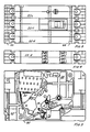
- FIG. 1 shows a pole of a power switch, with one housing part being removed in order to show assemblies mounted on the other housing part.
- FIG. 2 is a top view of the pole of the circuit breaker according to FIG. 1, individual parts being shown in section to show connecting elements of the two housing parts.
- Figure 3 is a view similar to Figure 1 showing the right pole of a three pole circuit breaker.
- FIG. 4 shows a top view similar to FIG. 2, but with the pole of the circuit breaker shown in FIG. 3.
- FIG. 5 shows a top view similar to FIGS. 2 and 4, but for a three-pole arrangement.
- FIG. 6 shows a view similar to FIGS. 1 and 3, but which shows the left pole of a multi-pole circuit breaker
- FIG. 7 is a plan view similar to FIGS. 2 and 4, but with the pole shown in FIG. 6.
- FIG. 8 is a view similar to FIGS. 3 and 6, but only shows the housing with the reinforcing ribs when the assemblies have been removed
- FIG. 9 shows a top view of the housing base shown in FIG. 8.
- FIG. 10 shows the outside of the housing part shown in FIG. 8 to show areas of different thickness.
- Figure 1 1 is a view of the corresponding to that shown in the Figure 8 housing part further housing part.
- FIG. 12 shows a view of the outside of the housing part shown in FIG. 11, while FIG. 1 3 shows a view of the housing part shown in FIG. 1 1 to illustrate areas of different thickness.
- a circuit breaker 10 of the MCCB type has a frame 12 with a drive device 1 4 which is attached to the frame 12.
- the drive device 14 has an actuating handle 16, which is used to operate the circuit breaker by hand.
- This handle 16 is used in the same way for switching the circuit breaker 10 on and off when the circuit breaker consists of the single pole shown or of several poles, as will be explained.
- the circuit breaker 10 also has a movable contact arrangement 18 and a lever mechanism 20 which connects the drive device 14 and the contact arrangement 18 for moving the contact arrangement 18 between the open and the closed position.
- the circuit breaker 10 also has a release lever 15, which acts by hand or automatically to trigger the circuit breaker. In multi-pole arrangements, the trip lever 15 of each pole is connected to the trip levers of the other poles to effect a common trip.
- the circuit breaker 10 has a housing 22 which consists of two parts, namely a first housing part 24 serving as a base and a second housing part 26 serving as a cover.
- the base 24 and the cover 26 are separately manufactured parts and consist preferably made of a glass fiber polyester material, which is well suited for the manufacture of switch housings.
- the two housing parts are designed to fit together and are connected to one another by pins or rivets or other connecting parts 28.
- the six housing parts required for a three-pole circuit breaker can be manufactured in a single mold. Therefore, the three poles 22 L, C and R ( Figure 5) are made in a single operation.
- each pole of the circuit breaker 10 has its own contact arrangement 18.
- the contact arrangement has an opening through which a cross member 30 (FIG. 2) extends for actuating the contact arm arrangement.
- the contact arrangement exerts forces on the housing during operation. Since the thickness of the housing walls and thus its strength is limited where the modules are arranged, longitudinal and transverse reinforcing ribs or projections 32 are provided in the region of the housing around the contact arrangement 18. Further projections are arranged in the area of the frame 12 and the drive device 1 4 . With this design, when the base 24 and the cover 26 are joined together, pockets are formed which accommodate the various drive arrangements and mechanisms of the circuit breaker. The housing is thus reinforced in the areas adjoining the modules, where the thickness of the housing is limited.
- reinforcing ribs 38 in the left and right poles are used to reinforce the thinner portions of the base 24 and cover 26 since there are no actuators with an operating handle included in these poles.
- the reinforcing ribs 38 can extend either in the longitudinal direction or in the transverse direction, depending on which type of reinforcement pattern is desired. In any case, the reinforcing ribs reinforce the area that would otherwise be the thinnest part of the housing 22.
- the opening for the release lever 15 can also be reinforced, since openings normally weaken a housing.
- the trigger lever 15 has a tab that extends through an opening in the housing to engage the flush or slightly recessed groove of a trigger lever of an adjacent pole.
- the outside of the housing 22 has a different thickness.
- area 40 is thicker than area 42, which provides additional material to increase the strength of those parts of the housing that support the assemblies. Since the thickness of the walls is limited by the available space, this additional material cannot always be applied, but there is always space for the ribs in a multi-pole arrangement because the drive device with the actuating handle is missing from the outer poles.
- the overall strength of the circuit breaker 10 in the multi-pole version can be increased by mechanically joining the poles together using rivets or other connecting elements 44.
- the reinforced poles 22 L and 22 R can be used to reinforce the central pole 22 C, which contains the drive device.
- the housing of a circuit breaker of the MCCB type is reinforced by the invention in such a way that it withstands the gas pressures and stresses during operation, particularly when high currents are interrupted.
- Transverse and longitudinal projections are arranged in the housing walls around the assemblies and the thinner sections of the housing walls are provided with ribs in order to increase the strength in a limited space.
- the reinforcement is relatively easy to implement since it only requires simple changes to the shape. These changes in shape are relatively simple because only half of the complete housing is affected. Due to the shape direction, the protrusions to form pockets for the switch assemblies make rivets, screws or other parts unnecessary, which simplifies assembly. At the same time, the projections and reinforcing ribs reinforce the housing walls and make them resistant to the gas pressure that occurs when high currents are interrupted.
Landscapes
- Breakers (AREA)
Applications Claiming Priority (2)
| Application Number | Priority Date | Filing Date | Title |
|---|---|---|---|
| US06/656,236 US4595896A (en) | 1984-10-01 | 1984-10-01 | Molded case circuit breaker having a reinforced housing |
| US656236 | 1984-10-01 |
Publications (2)
| Publication Number | Publication Date |
|---|---|
| EP0180537A2 true EP0180537A2 (fr) | 1986-05-07 |
| EP0180537A3 EP0180537A3 (fr) | 1987-08-19 |
Family
ID=24632211
Family Applications (1)
| Application Number | Title | Priority Date | Filing Date |
|---|---|---|---|
| EP85730127A Withdrawn EP0180537A3 (fr) | 1984-10-01 | 1985-09-17 | Interrupteur du type MCCB à deux parts de boíte |
Country Status (4)
| Country | Link |
|---|---|
| US (1) | US4595896A (fr) |
| EP (1) | EP0180537A3 (fr) |
| JP (1) | JPS6185743A (fr) |
| CA (1) | CA1241685A (fr) |
Cited By (4)
| Publication number | Priority date | Publication date | Assignee | Title |
|---|---|---|---|---|
| EP0320412A1 (fr) * | 1987-12-10 | 1989-06-14 | Merlin Gerin | Disjoncteur multipolaire de calibre élevé constitué par deux boîtiers moulés accolés |
| EP0456587A1 (fr) * | 1990-05-10 | 1991-11-13 | Schneider Electric Sa | Boîtier isolant pour un disjoncteur miniature équipÀ© de moyens de préassemblage |
| WO1992002944A1 (fr) * | 1990-07-30 | 1992-02-20 | Bticino S.P.A. | Electro-aimant de declenchement a aimant permanent pour disjoncteurs automatiques |
| CN104064410A (zh) * | 2013-03-20 | 2014-09-24 | 西门子公司 | 支承板 |
Families Citing this family (8)
| Publication number | Priority date | Publication date | Assignee | Title |
|---|---|---|---|---|
| DE3727357A1 (de) * | 1987-08-17 | 1989-03-02 | Asea Brown Boveri | Verankerung von einbauteilen in elektrischen schaltgeraeten |
| DE3825478A1 (de) * | 1988-07-27 | 1990-02-01 | Asea Brown Boveri | Elektrisches schaltgeraet |
| US4959806A (en) * | 1988-10-24 | 1990-09-25 | Eaton Corporation | Approximated rotational speed signal for shifting transmission |
| US5585609A (en) * | 1994-09-28 | 1996-12-17 | Siemens Energy & Automation, Inc. | Circuit breaker with movable main contact multi-force-level biasing element |
| US6005207A (en) * | 1997-09-23 | 1999-12-21 | Siemens Energy & Automation, Inc. | Multi-part circuit breaker housing |
| US5844187A (en) * | 1997-12-12 | 1998-12-01 | Siemens Energy & Automation, Inc. | Single piece arcing contact for a circuit breaker |
| US7358837B2 (en) * | 2006-04-12 | 2008-04-15 | Eaton Corporation | Electrical switching apparatus and circuit breaker including a molded enclosure and machine screws reinforcing the same |
| US7545247B2 (en) * | 2006-11-16 | 2009-06-09 | Eaton Corporation | Electrical switching apparatus, and case and terminal shield therefor |
Family Cites Families (8)
| Publication number | Priority date | Publication date | Assignee | Title |
|---|---|---|---|---|
| US3626338A (en) * | 1970-03-04 | 1971-12-07 | Heinemann Electric Co | Circuit breaker case structure |
| US3602852A (en) * | 1970-06-05 | 1971-08-31 | Wood Electric Corp | Case assembly for circuit breakers |
| US3842376A (en) * | 1971-08-02 | 1974-10-15 | Heinemann Electric Co | Fastener and circuit breaker case |
| US3953812A (en) * | 1974-10-09 | 1976-04-27 | General Electric Company | Electric circuit breaker |
| US4077024A (en) * | 1976-07-22 | 1978-02-28 | Heinemann Electric Company | Multi-pole circuit breaker |
| US4266209A (en) * | 1979-11-09 | 1981-05-05 | Gould Inc. | Circuit breaker handle and lost motion connected shield |
| JPS6032228A (ja) * | 1983-07-31 | 1985-02-19 | 松下電工株式会社 | 回路しゃ断器 |
| US4550300A (en) * | 1984-05-10 | 1985-10-29 | General Electric Company | Latch release mechanism for molded case electric circuit breakers |
-
1984
- 1984-10-01 US US06/656,236 patent/US4595896A/en not_active Expired - Lifetime
-
1985
- 1985-08-30 CA CA000489768A patent/CA1241685A/fr not_active Expired
- 1985-09-17 EP EP85730127A patent/EP0180537A3/fr not_active Withdrawn
- 1985-09-27 JP JP60214449A patent/JPS6185743A/ja active Pending
Cited By (11)
| Publication number | Priority date | Publication date | Assignee | Title |
|---|---|---|---|---|
| EP0320412A1 (fr) * | 1987-12-10 | 1989-06-14 | Merlin Gerin | Disjoncteur multipolaire de calibre élevé constitué par deux boîtiers moulés accolés |
| FR2624649A1 (fr) * | 1987-12-10 | 1989-06-16 | Merlin Gerin | Disjoncteur multipolaire de calibre eleve constitue par deux boitiers accoles |
| US4884047A (en) * | 1987-12-10 | 1989-11-28 | Merlin Gerin | High rating multipole circuit breaker formed by two adjoined molded cases |
| EP0456587A1 (fr) * | 1990-05-10 | 1991-11-13 | Schneider Electric Sa | Boîtier isolant pour un disjoncteur miniature équipÀ© de moyens de préassemblage |
| FR2662018A1 (fr) * | 1990-05-10 | 1991-11-15 | Merlin Gerin | Boitier isolant pour un disjoncteur miniature equipe de moyens de preassemblage. |
| WO1992002944A1 (fr) * | 1990-07-30 | 1992-02-20 | Bticino S.P.A. | Electro-aimant de declenchement a aimant permanent pour disjoncteurs automatiques |
| US5387892A (en) * | 1990-07-30 | 1995-02-07 | Bticino S.P.A. | Permanent magnet release solenoid for automatic circuit breakers and method of making |
| CN104064410A (zh) * | 2013-03-20 | 2014-09-24 | 西门子公司 | 支承板 |
| EP2782114A1 (fr) * | 2013-03-20 | 2014-09-24 | Siemens Aktiengesellschaft | Plaque de support |
| CN104064410B (zh) * | 2013-03-20 | 2017-01-04 | 西门子公司 | 支承板 |
| US9691564B2 (en) | 2013-03-20 | 2017-06-27 | Siemens Aktiengesellschaft | Mounting plate |
Also Published As
| Publication number | Publication date |
|---|---|
| CA1241685A (fr) | 1988-09-06 |
| US4595896A (en) | 1986-06-17 |
| JPS6185743A (ja) | 1986-05-01 |
| EP0180537A3 (fr) | 1987-08-19 |
Similar Documents
| Publication | Publication Date | Title |
|---|---|---|
| DE3531710C2 (de) | Durch Zusammenbau von Modulelementen realisierbare Schaltvorrichtung mit veränderlicher Zusammensetzung | |
| EP2135272B1 (fr) | Procédé de fabrication pour un commutateur électromagnétique comportant des parois de séparation entre des contacts principaux et de secours ainsi que commutateur électromagnétique fabriqué selon le procédé de fabrication | |
| DE3878429T2 (de) | Mehrpoliger schalter fuer hoeheren strombereich bestehend aus zwei verbundenen formgepressten gehaeusen. | |
| EP2061053A2 (fr) | Commutateur destiné à des applications à courant continu | |
| DE19910032C1 (de) | Mehrpoliger Leistungsschalter | |
| EP0727805B1 (fr) | Unité de levier de contact pour disjoncteur basse tension | |
| AT394284B (de) | Sicherheitslastschaltleiste (einbauleiste) | |
| EP0177438B1 (fr) | Interrupteur multipolaire avec des boîtiers séparés en matière isolante pour chaque pôle | |
| EP0000711B1 (fr) | Contacteur avec bornes de raccordement librement accessibles et disposées dans des plans différents | |
| DE69501439T2 (de) | LöSCHBLECHANORDNUNG FüR LASTSCHALTER | |
| DE2802554B1 (de) | Niederspannungs-Leistungsschalter mit durch Trennwaende unterteiltem Isolierstoffgehaeuse | |
| DE19939710A1 (de) | Anschlußschienen für elektrische Geräte und Apparate für verschiedene Nennströme | |
| EP0360366B1 (fr) | Boîtier moulé pour un disjoncteur électrique de puissance basse tension avec renfort contre une surpression | |
| DE69834897T2 (de) | Verwechslungsschutzanordnung für elektrische Schaltgeräte, insbesondere für Leistungsschalter und Differenzstromschutzschalter | |
| EP0003736A1 (fr) | Interrupteur de puissance à basse tension constitué d'un boîtier en matière isolante divisé en deux | |
| DE69308772T2 (de) | Moduläre Lastschalter für Gleichstrom | |
| DE2648964A1 (de) | Metallgekapselter sf tief 6 -isolierter schalter, insbesondere hochspannungs- leistungsschalter | |
| DE3850732T2 (de) | Gekapselte Gehäuse- und Deckelanordnung für Strombegrenzungsschalter. | |
| EP0634051B1 (fr) | Disjoncteur multipolaire a basse tension avec arbre de commande | |
| EP0309384B1 (fr) | Dispositif interrupteur multipolaire basse tension avec un boîtier isolant sous-divisé en chambres parallèles | |
| DE19948695B4 (de) | Niederspannungs-Leistungsschalter mit einem bewegbaren Kontaktträger mit Endlagen-Haltefeder | |
| DE3729741C2 (de) | Mehrpoliger Leistungsschalter | |
| EP0259800B1 (fr) | Disjoncteur de protection de ligne bipolaire | |
| DE2821563C2 (de) | Elektrischer Wickelkondensator mit Abschaltsicherung | |
| AT264649B (de) | Dreipoliger Hochspannungsschalter in gekapselter Bauweise |
Legal Events
| Date | Code | Title | Description |
|---|---|---|---|
| PUAI | Public reference made under article 153(3) epc to a published international application that has entered the european phase |
Free format text: ORIGINAL CODE: 0009012 |
|
| AK | Designated contracting states |
Kind code of ref document: A2 Designated state(s): DE FR GB IT |
|
| PUAL | Search report despatched |
Free format text: ORIGINAL CODE: 0009013 |
|
| AK | Designated contracting states |
Kind code of ref document: A3 Designated state(s): DE FR GB IT |
|
| 17P | Request for examination filed |
Effective date: 19870904 |
|
| 17Q | First examination report despatched |
Effective date: 19890125 |
|
| STAA | Information on the status of an ep patent application or granted ep patent |
Free format text: STATUS: THE APPLICATION HAS BEEN WITHDRAWN |
|
| 18W | Application withdrawn |
Withdrawal date: 19890424 |
|
| RIN1 | Information on inventor provided before grant (corrected) |
Inventor name: DIMARCO, BERNARD Inventor name: STANFORD, CHARLES W. |