EP0180590B1 - Procede de commande du remplissage repete de moules et installation appropriee - Google Patents
Procede de commande du remplissage repete de moules et installation appropriee Download PDFInfo
- Publication number
- EP0180590B1 EP0180590B1 EP19850901339 EP85901339A EP0180590B1 EP 0180590 B1 EP0180590 B1 EP 0180590B1 EP 19850901339 EP19850901339 EP 19850901339 EP 85901339 A EP85901339 A EP 85901339A EP 0180590 B1 EP0180590 B1 EP 0180590B1
- Authority
- EP
- European Patent Office
- Prior art keywords
- casting
- weight
- ladle
- level
- process according
- Prior art date
- Legal status (The legal status is an assumption and is not a legal conclusion. Google has not performed a legal analysis and makes no representation as to the accuracy of the status listed.)
- Expired
Links
- 238000000034 method Methods 0.000 title claims abstract description 41
- 230000008569 process Effects 0.000 title claims abstract description 38
- 238000005266 casting Methods 0.000 claims abstract description 121
- 239000002184 metal Substances 0.000 claims description 22
- 229910052751 metal Inorganic materials 0.000 claims description 22
- 238000009434 installation Methods 0.000 claims description 12
- 239000000523 sample Substances 0.000 claims description 11
- 238000000465 moulding Methods 0.000 claims description 10
- 238000012937 correction Methods 0.000 claims description 9
- XEEYBQQBJWHFJM-UHFFFAOYSA-N Iron Chemical compound [Fe] XEEYBQQBJWHFJM-UHFFFAOYSA-N 0.000 claims description 7
- 230000006870 function Effects 0.000 claims description 6
- 238000005303 weighing Methods 0.000 claims description 5
- 230000008859 change Effects 0.000 claims description 4
- 229910052742 iron Inorganic materials 0.000 claims description 3
- 210000000056 organ Anatomy 0.000 claims 5
- 238000013459 approach Methods 0.000 claims 1
- 230000002349 favourable effect Effects 0.000 claims 1
- 238000012986 modification Methods 0.000 claims 1
- 230000004048 modification Effects 0.000 claims 1
- 239000007921 spray Substances 0.000 claims 1
- 238000012800 visualization Methods 0.000 claims 1
- 238000005259 measurement Methods 0.000 abstract description 9
- 239000000155 melt Substances 0.000 abstract description 5
- 230000003287 optical effect Effects 0.000 abstract description 2
- 238000010586 diagram Methods 0.000 description 21
- 230000001419 dependent effect Effects 0.000 description 8
- 238000001514 detection method Methods 0.000 description 4
- 239000000463 material Substances 0.000 description 4
- 230000033228 biological regulation Effects 0.000 description 2
- 230000001914 calming effect Effects 0.000 description 2
- 210000004894 snout Anatomy 0.000 description 2
- 230000004580 weight loss Effects 0.000 description 2
- 230000001133 acceleration Effects 0.000 description 1
- 230000008901 benefit Effects 0.000 description 1
- 230000006378 damage Effects 0.000 description 1
- 238000011161 development Methods 0.000 description 1
- 238000005429 filling process Methods 0.000 description 1
- 239000002655 kraft paper Substances 0.000 description 1
- 230000007257 malfunction Effects 0.000 description 1
- 238000004519 manufacturing process Methods 0.000 description 1
- 238000012544 monitoring process Methods 0.000 description 1
- 230000035699 permeability Effects 0.000 description 1
- 238000002360 preparation method Methods 0.000 description 1
- 239000004576 sand Substances 0.000 description 1
- 239000002893 slag Substances 0.000 description 1
- 210000002023 somite Anatomy 0.000 description 1
- 238000005507 spraying Methods 0.000 description 1
- 230000003068 static effect Effects 0.000 description 1
- 238000003860 storage Methods 0.000 description 1
- 239000000725 suspension Substances 0.000 description 1
- 230000009747 swallowing Effects 0.000 description 1
- 239000002699 waste material Substances 0.000 description 1
- 238000004260 weight control Methods 0.000 description 1
Images


Classifications
-
- B—PERFORMING OPERATIONS; TRANSPORTING
- B22—CASTING; POWDER METALLURGY
- B22D—CASTING OF METALS; CASTING OF OTHER SUBSTANCES BY THE SAME PROCESSES OR DEVICES
- B22D39/00—Equipment for supplying molten metal in rations
- B22D39/04—Equipment for supplying molten metal in rations having means for controlling the amount of molten metal by weight
Definitions
- the present invention relates to a method for controlling the repeated pouring of metal into casting molds, according to the preamble of claim 1 and a casting installation according to the preamble of claim 18.
- a method and a casting installation of this type is known from US-A-3 007 347 , whereby the pouring process is controlled by the changing weight of the ladle.
- the aim of the present invention is to carry out greater safety and thus further automation by combining a weight-controlled casting process by weighing the casting container and level measurement in the pouring funnel of the casting mold.
- additional problems arise by z. B. a tilting ladle or a casting furnace in any case considerable inertial forces of the moving parts of the plant and / or the moving metal occur, which make the weight measurement very difficult.
- These mass forces occur precisely when optimal control is particularly difficult anyway, namely when casting, possibly also at the end of the casting process.
- the uncertainty of the control in these phases can be taken into account by a large pouring funnel, which is also undesirable.
- the invention aims to overcome all these problems and to achieve an optimal, automatic control of the casting process without weighing the mold, with a small pouring funnel and while maintaining the remaining amount of metal in the pouring funnel within narrow tolerances.
- the regulation of the pouring process should be optimized so that the pouring funnel always remains well filled.
- the characterizing part of claim 1 specifies the solution to the problem. It is thereby achieved that the casting process is controlled independently of the weight during casting, possibly also at the end of the casting process, where the determined weight profile is particularly strongly influenced or falsified by mass forces. During the longest middle part of the casting process, the weight-dependent control enables the conditions to be optimized.
- the invention also relates to a casting installation which allows a particularly precise detection of the weight or the changes in weight of a tiltable ladle. It is described in claim 18. In this way, the dead weight to be weighed can practically be reduced to that of the ladle itself.
- the casting can also be done very efficiently, because there are e.g. B. 10 castings from a pan possible, and this pan can be replaced by a quick change device in a short time.
- the ladle or holder for the same is suspended on the carrier by means of the force measuring elements, and all force measuring elements have the same length, such that they form a parallelogram with the ladle or a holder for the same and the carrier.
- the movements of the carrier are faithfully transferred to the ladle, which facilitates reliable control of the pouring process.
- the cable winch 10 can be driven by means of a motor 11 which can be controlled by a microprocessor 12.
- the casting process can be controlled by means of a control lever 13 which, for. B. actuates a potentiometer which at the same time controls the motor 11 via an AD converter of the microprocessor and allows the program to be stored, as will be explained below.
- a second input of the microprocessor is connected to the load cells 6. This schematic representation is intended to show that the signals from the four measuring sockets 6 are added electronically to a weight signal which indicates the weight of the holder 5, the casting ladle 4 and the melt therein with high accuracy.
- the motor can be a direct current motor which can be controlled forwards and backwards by corresponding output information from the microprocessor.
- a stepper motor can also be provided, which can be controlled directly by digital output signals of the microprocessor.
- a schematically indicated probe 14 allows the level of the metal in the pouring funnel 2 to be detected.
- a tachometer generator 15 and a position transmitter 16 are coupled to the cable winch 10 and are likewise connected to inputs of the microprocessor. There is also a screen 17 on which, for. B. certain curves can be made visible, as will be explained in more detail.
- the elements 15 and 16 can also be coupled to the motor 11, and instead of a cable winch 10, a chain wheel can be provided, over which a chain is placed.
- Diagram I shows the time course of the outflow of metal in kg / s
- Diagram II the setpoint curve of the time rise of the cast metal weight in kg
- Diagram 111 the tilting speed Ap of the pan
- Diagram IV the pan weight recorded by the load cells in kg, whereby all diagrams apply to a cast.
- the first casting process or pilot casting process is controlled manually by means of the control lever 13.
- the pan is initially quickly tilted forward to initiate the pouring process.
- Diagram IV in FIG. 2 shows the difference between the static weight of the ladle assumed before the casting and the measured weight. This representation of the difference, which corresponds to an increase in weight instead of a decrease in the pan, was chosen in order to achieve a corresponding course for diagrams II and IV.
- the weight curve according to Diagram IV is now saved during the manual casting process by the microprocessor in its memory by the measured weight z. B. is stored at intervals of 1/10 s.
- subsequent casting processes are then automatically controlled in that a follow-up control is carried out in such a way that the weight decrease over time corresponds to the manually specified one, ie. H. if, at a certain point in time, the measured weight is greater than the weight stored for the relevant point in time of the casting program, the amount of material spilled per unit of time is increased by tipping the pan more quickly.
- the tilting movement of the pan is slowed down or interrupted or the pan is tilted back, as indicated in diagram 111 in FIG. 2.
- the pan must be tilted without any material flowing out, in such a way that the process is not controlled according to the weight-time curve, but rather by a predetermined, arbitrarily selected program. Likewise, the end of the casting process is not weight-dependent, but can be controlled by combining it with a program part.
- the pouring ladle remains in the tilted position reached, as shown in diagram 111.
- a further predetermined weight limit is reached, the actual termination of the pouring process is initiated at point D by quickly tilting back the pouring ladle.
- the weights at which the pan is stopped and tipped back are entered after performing the manual casting process on the basis of empirical values or determined by means of a microprocessor, so that at the end of the casting process at point E the exact amount of metal required to fill the mold is poured out.
- the screen 17 can be used to program the microprocessor, on which certain or all of the curves of interest can be displayed.
- the course of the manual casting can be checked from curves 1, II and IV, and the weights determining the times C and D, and, if appropriate, also corresponding values for the weight loss according to curve I can be determined and entered. Further interventions in the stored data are necessary or possible. It has been found necessary to smooth the stored weight-time curve, which has fluctuations as shown in diagram IV, and to arrive at a curve according to diagram 11, thus avoiding vibrations in the automatic control. However, you can make further corrections that come from experience. So z. For example, experience shows that the first manual pouring is too heavy because the final level in the funnel is too high. A corresponding correction can be made for the following automatic casting processes.
- the load cells 6 can be blocked during these time periods to avoid vibrations.
- the time course of the level can be stored in the pouring funnel and, if necessary, can be displayed on the screen, and corrections can be entered in order to adapt the level course to an optimal target course.
- the purpose and aim of the automatic control described is, inter alia, to achieve a minimum filling weight of the mold as precisely as possible with a casting process which is dimensioned as precisely as possible and accordingly to manage with a casting funnel which is as small as possible.
- the level in the pouring funnel falls below a minimum level or exceeds a maximum level in order to increase or decrease the outflow quantity.
- the level is measured optically, e.g. B. by light-sensitive probes or by a video camera.
- the various corrections mentioned for optimizing the casting process can also be calculated using a microprocessor and corrected by appropriate interventions.
- the weight changes or the discharge quantities from the ladle (pouring speed according to diagram I) at which the ladle is to be stopped or tipped back at times C and D could also be determined by the microprocessor on the basis of the final weight or fill weight of the mold.
- the weights determining the completion of the casting process at times C and D are increased accordingly from the consideration that it is considerably cheaper, with a little too much Metal to fill the mold correctly instead of producing rejects.
- the level in the pouring funnel can be monitored at the end of the pouring in such a way that an alarm is actuated if the level is too low in order to trigger proposed corrective measures. If the final level is too high or the mold overflows, the program can be changed automatically via the microprocessor or arbitrarily so that excess material is not spilled during further casting processes.
- a corresponding weight-dependent control is also possible with other casting plants of a similar size.
- a corresponding weight-controlled, pressurized pouring device is also conceivable, since modern weighing systems also allow a sufficiently precise weight detection in this case.
- the measuring device shown in FIG. 1 for determining the weight of the casting ladle and the melt located therein has fundamental, independent significance beyond the method described above. It is not only possible to precisely weigh the pan contents, but the special suspension of the ladle in a parallelogram has the advantage that no material storage is required in the region of the pan muzzle and the position and movement of the muzzle are optimally determined.
- the load cells 6 always hang exactly vertically and thus convey precise weight measurements regardless of the pivoting position of the carrier 7 or the holder 5. If no weight detection is required, the load cells 6 can be replaced by rigid pulling elements.
- the pouring can also be controlled according to an arbitrarily specified program until a target level is reached in the pouring funnel, whereupon the weight-dependent control starts.
- This weight dependent control can be done in any of the ways mentioned above. Different variants are also possible for control at the end of the casting process. Depending on the expected duration of the overrun, the shutdown process can be initiated sooner or later. One can also try to regulate the end of a corresponding pouring from a corresponding point in time to a constant decrease in the casting speed or weight change (dG / dt), in which case the wake should always be the same. This section of the casting process can also be tested empirically and programmed accordingly.
- a fully automatic programming of the casting process can also be carried out, in that a pilot casting process is carried out purely level-controlled and the weight curve is saved.
- the ladle is tilted forward when the level in the pouring funnel is too low, and is stopped or tipped back when the level rises too high.
- the program saved in this way will still be unsatisfactory.
- This program is therefore used to control a second pilot casting process, while soft corrections are saved when limit levels are exceeded or fallen short of. This leads to a more refined program and the process can be repeated to achieve an even more optimal program.
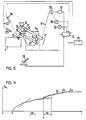
- FIG. 3 and 4 show a further embodiment of the casting installation or a concrete casting process.
- corresponding parts are designated the same as in Fig. 1 and they are not explained in detail.
- a probe in the form of a light-sensitive receiver 21 is provided, which makes it possible to determine whether metal is flowing out of the pan 4.
- the corresponding signal which indicates the presence or absence of the pouring jet, is fed to the microprocessor 12 via the line 22.
- the casting curve will run differently than the target curve provides.
- the detection of maximum and minimum levels by means of the level probe 14 must now function so that the funnel does not run empty (waste) or overflow. If signals appear that indicate that the maximum level has been exceeded or that the minimum level has not been reached, it can be concluded from the funnel shape to what extent it is necessary to correct. In the case of such a correction, the time in the setpoint curve must be gathered or stretched for the cast in question. This is shown in Figure 4, in which the solid line represents the target value of the weight profile (actually the weight loss). Critical deviations from the target course are indicated by dashed lines.
- this weight being a function of the final target weight G a , the average casting speed, the current ladle movement and the current casting speed, the tilting movement is stopped.
- the metal continues to flow out with increased weighing accuracy, since there are no longer any inertial forces and vibrations.
- the tilting back takes place by a certain angle at a certain speed, ie no longer weight-controlled.
- the so-called overrun is dependent on dG / dt, the pouring height, pan parameters and the tip-back speed.
- the preparation for the new cast is then carried out. After tipping back completely and a calming phase, tare is carried out to determine the zero point for the next cast.
- a level check is carried out in the pouring funnel via a further level probe and a decision is made as to whether the final level in the funnel is correct. If necessary, the wake can be corrected for further castings or the target weight G 3 can be redefined accordingly.
Landscapes
- Engineering & Computer Science (AREA)
- Mechanical Engineering (AREA)
- Casting Support Devices, Ladles, And Melt Control Thereby (AREA)
Abstract
Claims (25)
Applications Claiming Priority (2)
| Application Number | Priority Date | Filing Date | Title |
|---|---|---|---|
| CH179184 | 1984-04-10 | ||
| CH1791/84 | 1984-04-10 |
Publications (2)
| Publication Number | Publication Date |
|---|---|
| EP0180590A1 EP0180590A1 (fr) | 1986-05-14 |
| EP0180590B1 true EP0180590B1 (fr) | 1988-08-17 |
Family
ID=4218683
Family Applications (1)
| Application Number | Title | Priority Date | Filing Date |
|---|---|---|---|
| EP19850901339 Expired EP0180590B1 (fr) | 1984-04-10 | 1985-04-04 | Procede de commande du remplissage repete de moules et installation appropriee |
Country Status (4)
| Country | Link |
|---|---|
| EP (1) | EP0180590B1 (fr) |
| JP (1) | JPS61501832A (fr) |
| DE (1) | DE3564390D1 (fr) |
| WO (1) | WO1985004607A1 (fr) |
Families Citing this family (4)
| Publication number | Priority date | Publication date | Assignee | Title |
|---|---|---|---|---|
| JP4565240B2 (ja) * | 2006-04-07 | 2010-10-20 | 独立行政法人産業技術総合研究所 | 自動注湯システム |
| DE102006034044A1 (de) * | 2006-07-24 | 2008-01-31 | Abb Patent Gmbh | Verfahren zum Erfassen einer Gießkurve für eine Robotersteuerung und Erfassungssystem dazu |
| DE102007047926A1 (de) * | 2007-12-17 | 2009-06-18 | Reis Robotics Gmbh & Co. Maschinenfabrik | Verfahren zur Steuerung einer Ausgießbewegung eines Gießlöffels |
| WO2012074119A1 (fr) * | 2010-12-02 | 2012-06-07 | Sintokogio, Ltd. | Procédé et équipement de coulée automatique |
Family Cites Families (4)
| Publication number | Priority date | Publication date | Assignee | Title |
|---|---|---|---|---|
| US3599835A (en) * | 1968-09-20 | 1971-08-17 | Kocks Gmbh Friedrich | Dispensing apparatus for and methods of casting |
| DE2203015A1 (de) * | 1971-01-29 | 1972-08-17 | Outokumpu Oy | Verfahren und vorrichtung zur herstellung von gegenstaenden bestimmten gewichtes oder bestimmter groesse |
| US3818971A (en) * | 1971-05-27 | 1974-06-25 | E Schutz | Method for casting blocks |
| DE3007347A1 (de) * | 1980-02-27 | 1981-09-03 | Klöckner-Humboldt-Deutz AG, 5000 Köln | Automatische vergiesseinrichtung |
-
1985
- 1985-04-04 EP EP19850901339 patent/EP0180590B1/fr not_active Expired
- 1985-04-04 JP JP60501483A patent/JPS61501832A/ja active Pending
- 1985-04-04 WO PCT/CH1985/000055 patent/WO1985004607A1/fr not_active Ceased
- 1985-04-04 DE DE8585901339T patent/DE3564390D1/de not_active Expired
Also Published As
| Publication number | Publication date |
|---|---|
| WO1985004607A1 (fr) | 1985-10-24 |
| DE3564390D1 (en) | 1988-09-22 |
| JPS61501832A (ja) | 1986-08-28 |
| EP0180590A1 (fr) | 1986-05-14 |
Similar Documents
| Publication | Publication Date | Title |
|---|---|---|
| DE2254946A1 (de) | Anordnung zur automatischen dosierungskontrolle beim abgiessen aus giessoefen | |
| DE2430835C3 (de) | Vorrichtung zum Gießen von Gußwerkstücken | |
| DE1474594B2 (de) | Verfahren und Vorrichtung zum kon~ tinuierlichen, gravimetrischen Austragen eines Gutes aus einem Gutsbehälter | |
| DE2631015C3 (de) | Automatische MetallschmelzengieSanlage | |
| DE3020076C2 (de) | Regelvorrichtung für eine automatische Gießanlage | |
| DE2851256C2 (fr) | ||
| DE2923115A1 (de) | Anordnung beim kontinuierlichen giessen, wie z.b. beim stranggiessen | |
| DE1508203B2 (de) | Regelvorrichtung zum kontinuierlichen beaufschlagen eines behaelters mit einem konstanten strom fluessigen metalls | |
| DE69207816T2 (de) | Vorrichtung und Verfahren zum Giessen von Halbzeug | |
| WO1985004607A1 (fr) | Procede de commande du remplissage repete de moules et installation appropriee | |
| DE1217558B (de) | Verfahren zum Giessen von Formaten | |
| AT505123B1 (de) | Verfahren und vorrichtung zum giessen von formteilen, insbesondere von nicht-eisen-anoden | |
| DE2709052C3 (de) | Verfahren und Vorrichtung zum Eingießen vorbestimmter Metallschmelzenmengen in aufeinanderfolgende Kokillen | |
| DE2440414A1 (de) | Anordnung zur steuerung einer mehradrigen stranggiessanlage | |
| EP0116030B1 (fr) | Procédé de contrôle d'une machine de coulée continue courbe | |
| DE2011698C2 (de) | Verfahren und Einrichtung zum gewichts genauen Gießen von Metallplatten, insbeson dere von Kupfer Anodenplatten | |
| DE862486C (de) | Anlage zum kontinuierlichen Giessen von Straengen aus hochschmelzenden Metallen | |
| DE3007347A1 (de) | Automatische vergiesseinrichtung | |
| DE3010811C2 (de) | Einrichtung zum Regeln der Schmelzenzufuhr während des Anfahrens einer Stranggießanlage | |
| DE3320435A1 (de) | Automatischer giessofen | |
| DE2351816B2 (de) | Verfahren und einrichtung zum regeln der fuellstandshoehe von schmelze in kokillen von stranggiessanlagen | |
| DE3608503A1 (de) | Verfahren zum automatischen angiessen eines stranges von stranggiessanlagen | |
| DE4210595C2 (de) | Automatisches Metallschmelzenverteilungssystem | |
| DE2817115A1 (de) | Verfahren zur steuerung eines giesspfannenschiebers beim stranggiessen | |
| CA1086961A (fr) | Appareil et methode pour introduire, a regime variable, un additif dans un metal en fusion |
Legal Events
| Date | Code | Title | Description |
|---|---|---|---|
| PUAI | Public reference made under article 153(3) epc to a published international application that has entered the european phase |
Free format text: ORIGINAL CODE: 0009012 |
|
| AK | Designated contracting states |
Kind code of ref document: A1 Designated state(s): BE CH DE FR GB LI |
|
| 17P | Request for examination filed |
Effective date: 19860410 |
|
| 17Q | First examination report despatched |
Effective date: 19861010 |
|
| GRAA | (expected) grant |
Free format text: ORIGINAL CODE: 0009210 |
|
| AK | Designated contracting states |
Kind code of ref document: B1 Designated state(s): BE CH DE FR GB LI |
|
| REF | Corresponds to: |
Ref document number: 3564390 Country of ref document: DE Date of ref document: 19880922 |
|
| GBT | Gb: translation of ep patent filed (gb section 77(6)(a)/1977) | ||
| ET | Fr: translation filed | ||
| PGFP | Annual fee paid to national office [announced via postgrant information from national office to epo] |
Ref country code: GB Payment date: 19890331 Year of fee payment: 5 |
|
| PLBE | No opposition filed within time limit |
Free format text: ORIGINAL CODE: 0009261 |
|
| STAA | Information on the status of an ep patent application or granted ep patent |
Free format text: STATUS: NO OPPOSITION FILED WITHIN TIME LIMIT |
|
| 26N | No opposition filed | ||
| PG25 | Lapsed in a contracting state [announced via postgrant information from national office to epo] |
Ref country code: GB Effective date: 19900404 |
|
| PGFP | Annual fee paid to national office [announced via postgrant information from national office to epo] |
Ref country code: CH Payment date: 19900423 Year of fee payment: 6 |
|
| GBPC | Gb: european patent ceased through non-payment of renewal fee | ||
| PG25 | Lapsed in a contracting state [announced via postgrant information from national office to epo] |
Ref country code: LI Effective date: 19910430 Ref country code: CH Effective date: 19910430 |
|
| REG | Reference to a national code |
Ref country code: CH Ref legal event code: PL |
|
| PGFP | Annual fee paid to national office [announced via postgrant information from national office to epo] |
Ref country code: FR Payment date: 19940322 Year of fee payment: 10 |
|
| PGFP | Annual fee paid to national office [announced via postgrant information from national office to epo] |
Ref country code: BE Payment date: 19940408 Year of fee payment: 10 |
|
| PGFP | Annual fee paid to national office [announced via postgrant information from national office to epo] |
Ref country code: DE Payment date: 19940503 Year of fee payment: 10 |
|
| PG25 | Lapsed in a contracting state [announced via postgrant information from national office to epo] |
Ref country code: BE Effective date: 19950430 |
|
| BERE | Be: lapsed |
Owner name: MASCHINENFABRIK & EISENGIESSEREI ED. MEZGER A.G. Effective date: 19950430 |
|
| PG25 | Lapsed in a contracting state [announced via postgrant information from national office to epo] |
Ref country code: FR Effective date: 19951229 |
|
| PG25 | Lapsed in a contracting state [announced via postgrant information from national office to epo] |
Ref country code: DE Effective date: 19960103 |
|
| REG | Reference to a national code |
Ref country code: FR Ref legal event code: ST |