EP0180632B1 - Schlauchpumpe - Google Patents
Schlauchpumpe Download PDFInfo
- Publication number
- EP0180632B1 EP0180632B1 EP85902506A EP85902506A EP0180632B1 EP 0180632 B1 EP0180632 B1 EP 0180632B1 EP 85902506 A EP85902506 A EP 85902506A EP 85902506 A EP85902506 A EP 85902506A EP 0180632 B1 EP0180632 B1 EP 0180632B1
- Authority
- EP
- European Patent Office
- Prior art keywords
- ring
- rollers
- hose
- pump
- squeeze
- Prior art date
- Legal status (The legal status is an assumption and is not a legal conclusion. Google has not performed a legal analysis and makes no representation as to the accuracy of the status listed.)
- Expired
Links
- 230000002572 peristaltic effect Effects 0.000 title claims description 18
- 239000007788 liquid Substances 0.000 abstract 1
- 238000010276 construction Methods 0.000 description 3
- 229910000639 Spring steel Inorganic materials 0.000 description 2
- 238000005516 engineering process Methods 0.000 description 2
- 238000004026 adhesive bonding Methods 0.000 description 1
- 239000003814 drug Substances 0.000 description 1
- 238000003780 insertion Methods 0.000 description 1
- 230000037431 insertion Effects 0.000 description 1
- 238000004519 manufacturing process Methods 0.000 description 1
- 239000000463 material Substances 0.000 description 1
- 230000002787 reinforcement Effects 0.000 description 1
Images

Classifications
-
- F—MECHANICAL ENGINEERING; LIGHTING; HEATING; WEAPONS; BLASTING
- F04—POSITIVE - DISPLACEMENT MACHINES FOR LIQUIDS; PUMPS FOR LIQUIDS OR ELASTIC FLUIDS
- F04B—POSITIVE-DISPLACEMENT MACHINES FOR LIQUIDS; PUMPS
- F04B43/00—Machines, pumps, or pumping installations having flexible working members
- F04B43/12—Machines, pumps, or pumping installations having flexible working members having peristaltic action
- F04B43/1253—Machines, pumps, or pumping installations having flexible working members having peristaltic action by using two or more rollers as squeezing elements, the rollers moving on an arc of a circle during squeezing
Definitions
- the invention relates to a peristaltic pump with pinch rollers rotating on a circular path and a ring which tightly surrounds the roller circle and presses a hose arranged on its inner circumference against the pinch rollers.
- Peristaltic pumps of this type often also referred to as “roller pumps” or “peristaltic pumps” - are used as laboratory devices and are also used in a variety of ways in medical technology. In medical technology, they are used very frequently for routine tasks that require the hose to be inserted quickly and safely. The hose is usually a disposable part that is used only once.
- a peristaltic pump of the type mentioned at the outset is known, for example, from FR-A-1 067 081.
- the pinch rollers are inelastically mounted on the rotor.
- the ring which closely surrounds the roller circle is largely inelastic, so that an extraordinarily great fit is required during assembly in order to achieve uniform squeezing forces along the roller circle. Accordingly, in this known hose pump, changing the hose is extremely time-consuming.
- a peristaltic pump in which handling, in particular the insertion of the hose, is significantly facilitated, is described in DE-B-23 58 228. These and other peristaltic pumps for easier handling, however, require an increased design effort for the already not very simple mechanical construction of the peristaltic pumps.
- the function of the peristaltic pump is irrelevant whether the rollers press resiliently against the fixed squeeze track or the squeeze track resiliently presses against the rollers.
- the simplest peristaltic pumps have only two pinch rollers and the pinch path forms at least a semicircle. In the case of a semicircle, it is difficult and complex to generate a uniform radial squeezing force with the resilient squeeze path. That is why the cheaper peristaltic pumps with only two pinch rollers also have spring-loaded rollers, which in turn means an increase in price.
- Peristaltic pumps in which the squeeze track resiliently presses against the rollers are usually designed to be even more complex.
- the Quetschbahn is almost a straight line (/ 8 circle l) is performed; at the hose pump according to PCT / WO 82/00498 the Quetschbahn forms a quarter circle, as in the tube pump according to DE-C 26 51 962 in which case the adjustment of the Quetschbahn or its abutment is critical.
- the object of the invention is to further develop the hose pump of the type mentioned at the outset such that the hose can be easily replaced and a uniformly large squeezing force can be achieved without additional structural effort along the roller circle.
- the invention proposes, starting from a peristaltic pump of the type mentioned at the outset, that the ring is of resilient design, has a smaller diameter than the circumference of the roller in the relaxed circular state, is elastically oval or multi-arcuate deformed by the pressing forces in the inserted state and is radial formable but secured against circulation.
- the resilient ring can be designed, for example, as a spring steel ring which surrounds a plastic ring which is not too hard and into which the hose is inserted in a non-slip manner. For assembly purposes, this ring can be compressed into an ellipse and placed over the pinch rollers.
- the resilient ring has one or more axially parallel pins which protrude into radial elongated holes in the base plate and secure the ring against rotation without impeding its radial deformability.
- the resilient ring is firmly connected to the hose, so that the hose and the ring form a replaceable unit.
- This unit will usually be made entirely of plastic as a disposable valve; a reinforcement by a spring steel ring can usually be omitted.
- the hose pump shown in the drawing has a resilient ring 1 which is glued to a hose 2.
- the ring 1 is provided with two retaining pins 3, which are made of the same material as the ring 1, and encloses - elastically oval (see FIG. 1) or, in the case of more squeezing rolls, deformed in multiple arches - a rotor 4 which is provided with two squeezing rolls 5 which are guided by the rotor 4 along a circular path, the diameter of which is larger than the diameter of the corresponding undeformed ring 1 (cf. FIG. 3).
- the rotor 4 is provided with a roller carrier 8, which protrudes slightly beyond the roller surface so that the ring 1 cannot slide off the pinch rollers 5.
- the spring ring 1 provided with the hose 2 is deformed by hand into an ellipse and placed over the rotor 4 such that it surrounds the two pinch rollers 5 and the retaining pins 3 engage in the elongated holes 6 of the base plate 7.
- the resilient ring 1 remains deformed so that its spring force presses evenly radially against the pinch rollers 5.
- the test model showed that the peristaltic pump according to the invention is functional even without gluing between the hose 2 and the resilient ring 1. In this case, the clamping of the hose on the bushing 9 by the elastic ring 1 is already sufficient for the hose 2 to be adequately held.
Landscapes
- Engineering & Computer Science (AREA)
- Mechanical Engineering (AREA)
- General Engineering & Computer Science (AREA)
- Reciprocating Pumps (AREA)
Description
- Die Erfindung betrifft eine Schlauchpumpe mit auf einer Kreisbahn umlaufenden Quetschrollen und einem den Rollenkreis eng umschliessenden Ring, der einen an seinem inneren Umfang angeordneten Schlauch gegen die Quetschrollen anpresst.
- Solche Schlauchpumpen - oft auch als «Rollenpumpen» oder «Peristaltische Pumpen» bezeichnet-werden als Laborgeräte verwendet und finden darüberhinaus besonders vielfältige Anwendung in der Medizintechnik. In der Medizintechnik werden sie sehr häufig bei Routineaufgaben eingesetzt, bei denen ein rasches und sicheres Einlegen des Schlauches erforderlich ist. Hierbei ist der Schlauch gewöhnlich ein Wegwerfteil, welches nur einmal benutzt wird.
- Eine Schlauchpumpe der eingangs genannten Art ist beispielsweise aus der FR-A-1 067 081 bekannt. Bei dieser bekannten Schlauchpumpe sind die Quetschrollen unelastisch an dem Rotor gelagert. Ebenso ist der den Rollenkreis eng umschliesssende Ring weitgehend unelastisch ausgebildet, so dass beim Zusammenbau eine ausserordentlich grosse Passgenauigkeit erforderlich ist, um entlang dem Rollenkreis gleichmässige Quetschkräfte zu erzielen. Dementsprechend ist bei dieser vorbekannten Schlauchpumpe das Auswechseln des Schlauches ausserordentlich zeitaufwendig.
- Eine Schlauchpumpe, bei der die Handhabung, insbesondere das Einlegen des Schlauches bedeutend erleichtert ist, ist in der DE-B-23 58 228 beschrieben. Diese und andere Schlauchpumpen für die erleichterte Handhabung erfordern jedoch einen erhöhten konstruktiven Aufwand für den ohnehin schon nicht sehr einfachen mechanischen Aufbau der Schlauchpumpen.
- Ob die Rollen federnd gegen die feste Quetschbahn oder die Quetschbahn federnd gegen die Rollen drückt, ist für die Funktion der Schlauchpumpe unerheblich. Die einfachsten Schlauchpumpen besitzen nur zwei Quetschrollen und die Quetschbahn bildet mindestens einen Halbkreis. Bei einem Halbkreis ist es schwierig und aufwendig, mit der federnden Quetschbahn eine gleichmässige radiale Quetschkraft zu erzeugen. Deshalb haben auch die billigeren Schlauchpumpen mit nur zwei Quetschrollen federnd gelagerte Rollen, was wiederum eine Verteuerung bedeutet. Schlauchpumpen, bei denen die Quetschbahn federnd gegen die Rollen drückt, sind in der Regel noch aufwendiger konstruiert. Bei der Konstruktion nach der DE-B-23 58 228 ist die Quetschbahn nahezu geradlinig (l/8 -Kreis) ausgeführt; bei den Schlauchpumpen nach PCT/WO 82/00498 bildet die Quetschbahn einen 1/4-Kreis, ebenso bei der Schlauchpumpe nach DE-C 26 51 962, wobei dann die Justierung der Quetschbahn bzw. ihres Widerlagers kritisch ist.
- Aufgabe der Erfindung ist es, die Schlauchpumpe der eingangs genannten Art dahingehend weiterzubilden, dass der Schlauch leicht ausgewechselt werden kann und ohne zusätzlichen baulichen Aufwand entlang dem Rollenkreis eine gleichmässig grosse Quetschkraft erzielbar ist.
- Zur Lösung dieser Aufgabe schlägt die Erfindung ausgehend von einer Schlauchpumpe der eingangs genannten Art vor, dass der Ring federnd ausgebildet ist, im entspannten kreisförmigen Zustand einen kleineren Durchmesser als der Rollenumkreis hat, im eingesetzten Zustand durch die Presskräfte elastisch oval oder mehrbogig verformt ist und radial ausformbar aber gegen Umlauf gesichert festgelegt ist.
- Der federnde Ring kann beispielsweise als Federstahlring ausgebildet sein, der einen nicht zu harten Kunststoffring umschliesst, in den der Schlauch rutschfest eingelegt ist. Zum Zwecke der Montage kann dieser Ring zu einer Ellipse zusammengedrückt und über die Quetschrollen gestülpt werden. Der federnde Ring weist einen oder mehrere achsparallele Stifte auf, die in radiale Langlöcherder Grundplatte hineinragen und den Ring gegen Verdrehen sichern, ohne seine radiale Verformbarkeit zu behindern.
- Um die Handhabung, insbesondere für Routinearbeiten in der Medizin, zu erleichtern, wird nach einer weiteren Ausgestaltung der Erfindung der federnde Ring fest mit dem Schlauch verbunden, so dass der Schlauch und der Ring eine auswechselbare Einheit bilden.
- Diese Einheit wird gewöhnlich als Wegwerfventil ganz aus Kunststoff bestehen; eine Verstärkung durch einen Federstahlring kann meist entfallen.
- Die mit der Erfindung erzielten Vorteile bestehen insbesondere darin, dass die Handhabung der Schlauchpumpe einfach ist und wegen der Einfachheit der Konstruktion die Herstellungskosten niedrig sind.
- Ein Ausführungsbeispiel der Erfindung ist in der Zeichnung dargestellt und wird im folgenden näher beschrieben. Es zeigen:
- Fig. 1 eine Draufsicht auf die Grundplatte und den Rotor einer Schlauchpumpe gemäss der Erfindung;
- Fig. 2 einen Schnitt durch die Grundplatte und den Rotor der Schlauchpumpe gemäss der Erfindung;
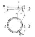
- Fig. 3 einen Schnitt durch den federnden Ring mit Schlauch der Schlauchpumpe gemäss der Erfindung entlang der Linie 111-111 in Fig. 4;
- Fig. 4 einen Schnitt durch den federnden Ring mit Schlauch der Schlauchpumpe gemäss der Erfindung entlang der Linie IV-IV in Fig. 3.
- Die in der Zeichnung dargestellte Schlauchpumpe weist einen federnden Ring 1 auf, der mit einem Schlauch 2 verklebt ist. Der Ring 1 ist mit zwei Haltestiften 3 versehen, die aus dem gleichen Material wie der Ring 1 bestehen, und umschliesst - elastisch oval (vgl. Fig. 1) oder bei mehr Quetschrollen mehrbogig verformt - einen Rotor 4, der mit zwei Quetschrollen 5 versehen ist, die von dem Rotor 4 entlang einer Kreisbahn geführt werden, deren Durchmesser grösser ist, als der Durchmesser des entsprechenden unverformten Ringes 1 (vgl. Fig. 3). Die parallel zur Achse des Ringes 1 verlaufenden Haltestifte 3 greifen in radial verlaufende Langlöcher 6 einer Grundplatte 7 ein, derart, dass der Ring 1 gegen Verdrehung gesichert, in radialer Richtung jedoch nicht festgelegt ist. Der Rotor 4 ist mit einem Rollenträger 8 versehen, der etwas über die Rollenoberfläche hinaussteht so dass der Ring 1 nicht von den Quetschrollen 5 abrutschen kann.
- Zur Montage wird der mit dem Schlauch 2 versehene Federring 1 mit der Hand zu einer Ellipse verformt und über den Rotor 4 gestülpt, derart, dass er die beiden Quetschrollen 5 umschliesst und die Haltestifte 3 in die Langlöcher 6 der Grundplatte 7 eingreifen. Der federnde Ring 1 bleibt dabei verformt, so dass seine Federkraft gleichmässig radial gegen die Quetschrollen 5 drückt.
- Beim Versuchsmodell zeigte sich, dass die Schlauchpumpe gemäss der Erfindung auch ohne Verklebung zwischen dem Schlauch 2 und dem federnden Ring 1 funktionstüchtig ist. In diesem Falle reicht die Klemmung des Schlauches an der Durchführung 9 durch den elastischen Ring 1 bereits für eine ausreichende Halterung des Schlauches 2 aus.
Claims (2)
Priority Applications (1)
| Application Number | Priority Date | Filing Date | Title |
|---|---|---|---|
| AT85902506T ATE38266T1 (de) | 1984-05-07 | 1985-05-07 | Schlauchpumpe. |
Applications Claiming Priority (2)
| Application Number | Priority Date | Filing Date | Title |
|---|---|---|---|
| DE3416776 | 1984-05-07 | ||
| DE3416776A DE3416776A1 (de) | 1984-05-07 | 1984-05-07 | Schlauchpumpe |
Publications (2)
| Publication Number | Publication Date |
|---|---|
| EP0180632A1 EP0180632A1 (de) | 1986-05-14 |
| EP0180632B1 true EP0180632B1 (de) | 1988-10-26 |
Family
ID=6235107
Family Applications (1)
| Application Number | Title | Priority Date | Filing Date |
|---|---|---|---|
| EP85902506A Expired EP0180632B1 (de) | 1984-05-07 | 1985-05-07 | Schlauchpumpe |
Country Status (3)
| Country | Link |
|---|---|
| EP (1) | EP0180632B1 (de) |
| DE (2) | DE3416776A1 (de) |
| WO (1) | WO1985005153A1 (de) |
Family Cites Families (5)
| Publication number | Priority date | Publication date | Assignee | Title |
|---|---|---|---|---|
| FR1351813A (fr) * | 1964-05-11 | Mecanique Generale De L Ouest | Pompe à rouleaux épicycloïdaux | |
| US2483924A (en) * | 1946-06-10 | 1949-10-04 | Moulinier Edmond Jean | Pump |
| FR1067081A (fr) * | 1952-11-24 | 1954-06-11 | Dispositif de compression pour installations frigorifiques | |
| FR1328484A (fr) * | 1962-04-18 | 1963-05-31 | Pompe à galets | |
| DE2153052A1 (de) * | 1971-10-25 | 1973-05-03 | Allen Longford & Associates Lt | Schlauchpumpe |
-
1984
- 1984-05-07 DE DE3416776A patent/DE3416776A1/de not_active Withdrawn
-
1985
- 1985-05-07 WO PCT/EP1985/000203 patent/WO1985005153A1/de not_active Ceased
- 1985-05-07 EP EP85902506A patent/EP0180632B1/de not_active Expired
- 1985-05-07 DE DE8585902506T patent/DE3565875D1/de not_active Expired
Also Published As
| Publication number | Publication date |
|---|---|
| DE3565875D1 (en) | 1988-12-01 |
| EP0180632A1 (de) | 1986-05-14 |
| DE3416776A1 (de) | 1985-11-07 |
| WO1985005153A1 (fr) | 1985-11-21 |
Similar Documents
| Publication | Publication Date | Title |
|---|---|---|
| DE1500257B1 (de) | Rueckschlagventil fuer Rohrleitungen | |
| DE2000921A1 (de) | Dichtungsanordnung | |
| DE1292974B (de) | Gleitringdichtung | |
| DE8223902U1 (de) | Vorrichtung zum verbinden eines kunststoffrohres mit einem rohrstutzen | |
| DE2841116C2 (de) | Vorrichtung zum Abziehen von Hülsen, Lagerringen o.dgl. | |
| DE2604002B2 (de) | Schlauchpumpe | |
| EP0088928A2 (de) | Dosierpistole | |
| DE2112385A1 (de) | Farbroller | |
| DE29904071U1 (de) | Kartuschenpresse mit einer Kartuschenhalterung | |
| DE3621637C2 (de) | ||
| DE1302962B (de) | ||
| DE2932879C2 (de) | Vorrichtung zur kraftschlüssigen, drehmomentübertragenden Verbindung einer Welle mit einem Nabenteil | |
| DE816929C (de) | Anordnung fuer Pressverbaende | |
| DE1072028B (de) | ||
| DE1500068B2 (de) | Ringventil | |
| DE2420963A1 (de) | Werkzeug zum zusammendruecken von federn | |
| DE2757901C3 (de) | Anschlußvorrichtung für einen Metallschlauch | |
| DE1097217B (de) | Verstellbare Klemmvorrichtung fuer Stangen, Rohre od. dgl. | |
| EP1034848A2 (de) | Kartuschenpresse mit einer Katuschenhalterung | |
| DE656033C (de) | Gebogene Breitstreckwalze mit Gummibezug | |
| DE460240C (de) | Reibungsfeder | |
| DE808514C (de) | Ventil, insbesondere Hochdruckventil | |
| DE3910732C2 (de) | ||
| DE2134732C3 (de) | Rohrschnellkupplung | |
| WO1985005153A1 (fr) | Pompe tubulaire |
Legal Events
| Date | Code | Title | Description |
|---|---|---|---|
| PUAI | Public reference made under article 153(3) epc to a published international application that has entered the european phase |
Free format text: ORIGINAL CODE: 0009012 |
|
| AK | Designated contracting states |
Kind code of ref document: A1 Designated state(s): AT BE CH DE FR GB IT LI LU NL SE |
|
| 17P | Request for examination filed |
Effective date: 19860515 |
|
| 17Q | First examination report despatched |
Effective date: 19870326 |
|
| ITF | It: translation for a ep patent filed | ||
| GRAA | (expected) grant |
Free format text: ORIGINAL CODE: 0009210 |
|
| AK | Designated contracting states |
Kind code of ref document: B1 Designated state(s): AT BE CH DE FR GB IT LI LU NL SE |
|
| REF | Corresponds to: |
Ref document number: 38266 Country of ref document: AT Date of ref document: 19881115 Kind code of ref document: T |
|
| GBT | Gb: translation of ep patent filed (gb section 77(6)(a)/1977) | ||
| REF | Corresponds to: |
Ref document number: 3565875 Country of ref document: DE Date of ref document: 19881201 |
|
| ET | Fr: translation filed | ||
| PGFP | Annual fee paid to national office [announced via postgrant information from national office to epo] |
Ref country code: SE Payment date: 19890428 Year of fee payment: 5 |
|
| PGFP | Annual fee paid to national office [announced via postgrant information from national office to epo] |
Ref country code: CH Payment date: 19890502 Year of fee payment: 5 |
|
| PGFP | Annual fee paid to national office [announced via postgrant information from national office to epo] |
Ref country code: LU Payment date: 19890503 Year of fee payment: 5 |
|
| PGFP | Annual fee paid to national office [announced via postgrant information from national office to epo] |
Ref country code: BE Payment date: 19890505 Year of fee payment: 5 |
|
| PGFP | Annual fee paid to national office [announced via postgrant information from national office to epo] |
Ref country code: FR Payment date: 19890525 Year of fee payment: 5 |
|
| ITTA | It: last paid annual fee | ||
| PG25 | Lapsed in a contracting state [announced via postgrant information from national office to epo] |
Ref country code: LU Free format text: LAPSE BECAUSE OF NON-PAYMENT OF DUE FEES Effective date: 19890531 |
|
| PGFP | Annual fee paid to national office [announced via postgrant information from national office to epo] |
Ref country code: NL Payment date: 19890531 Year of fee payment: 5 Ref country code: GB Payment date: 19890531 Year of fee payment: 5 Ref country code: AT Payment date: 19890531 Year of fee payment: 5 |
|
| PGFP | Annual fee paid to national office [announced via postgrant information from national office to epo] |
Ref country code: DE Payment date: 19890731 Year of fee payment: 5 |
|
| PLBE | No opposition filed within time limit |
Free format text: ORIGINAL CODE: 0009261 |
|
| STAA | Information on the status of an ep patent application or granted ep patent |
Free format text: STATUS: NO OPPOSITION FILED WITHIN TIME LIMIT |
|
| 26N | No opposition filed | ||
| PG25 | Lapsed in a contracting state [announced via postgrant information from national office to epo] |
Ref country code: GB Effective date: 19900507 Ref country code: AT Effective date: 19900507 |
|
| PG25 | Lapsed in a contracting state [announced via postgrant information from national office to epo] |
Ref country code: SE Effective date: 19900508 |
|
| PG25 | Lapsed in a contracting state [announced via postgrant information from national office to epo] |
Ref country code: LI Effective date: 19900531 Ref country code: CH Effective date: 19900531 Ref country code: BE Effective date: 19900531 |
|
| BERE | Be: lapsed |
Owner name: BOHM GUNTHER Effective date: 19900531 Owner name: BEERWALD HANS Effective date: 19900531 Owner name: GLOMSKI GUNTER Effective date: 19900531 |
|
| PG25 | Lapsed in a contracting state [announced via postgrant information from national office to epo] |
Ref country code: NL Effective date: 19901201 |
|
| GBPC | Gb: european patent ceased through non-payment of renewal fee | ||
| NLV4 | Nl: lapsed or anulled due to non-payment of the annual fee | ||
| PG25 | Lapsed in a contracting state [announced via postgrant information from national office to epo] |
Ref country code: FR Effective date: 19910131 |
|
| REG | Reference to a national code |
Ref country code: CH Ref legal event code: PL |
|
| PG25 | Lapsed in a contracting state [announced via postgrant information from national office to epo] |
Ref country code: DE Effective date: 19910201 |
|
| REG | Reference to a national code |
Ref country code: FR Ref legal event code: ST |
|
| EUG | Se: european patent has lapsed |
Ref document number: 85902506.6 Effective date: 19910115 |