EP0180660B1 - Dispositif de fermeture pour le réservoir d'une moissonneuse - Google Patents
Dispositif de fermeture pour le réservoir d'une moissonneuse Download PDFInfo
- Publication number
- EP0180660B1 EP0180660B1 EP84113448A EP84113448A EP0180660B1 EP 0180660 B1 EP0180660 B1 EP 0180660B1 EP 84113448 A EP84113448 A EP 84113448A EP 84113448 A EP84113448 A EP 84113448A EP 0180660 B1 EP0180660 B1 EP 0180660B1
- Authority
- EP
- European Patent Office
- Prior art keywords
- opening
- rear wall
- wall
- collecting container
- container
- Prior art date
- Legal status (The legal status is an assumption and is not a legal conclusion. Google has not performed a legal analysis and makes no representation as to the accuracy of the status listed.)
- Expired
Links
- 239000011324 bead Substances 0.000 claims description 13
- 239000000463 material Substances 0.000 claims description 10
- 238000003306 harvesting Methods 0.000 claims description 6
- 230000001154 acute effect Effects 0.000 claims description 3
- 238000004378 air conditioning Methods 0.000 description 1
- 238000000034 method Methods 0.000 description 1
- 238000007789 sealing Methods 0.000 description 1
Images

Classifications
-
- A—HUMAN NECESSITIES
- A01—AGRICULTURE; FORESTRY; ANIMAL HUSBANDRY; HUNTING; TRAPPING; FISHING
- A01D—HARVESTING; MOWING
- A01D41/00—Combines, i.e. harvesters or mowers combined with threshing devices
- A01D41/12—Details of combines
- A01D41/127—Control or measuring arrangements specially adapted for combines
- A01D41/1277—Control or measuring arrangements specially adapted for combines for measuring grain quality
-
- A—HUMAN NECESSITIES
- A01—AGRICULTURE; FORESTRY; ANIMAL HUSBANDRY; HUNTING; TRAPPING; FISHING
- A01D—HARVESTING; MOWING
- A01D41/00—Combines, i.e. harvesters or mowers combined with threshing devices
- A01D41/12—Details of combines
- A01D41/1208—Tanks for grain or chaff
-
- G—PHYSICS
- G01—MEASURING; TESTING
- G01N—INVESTIGATING OR ANALYSING MATERIALS BY DETERMINING THEIR CHEMICAL OR PHYSICAL PROPERTIES
- G01N1/00—Sampling; Preparing specimens for investigation
- G01N1/02—Devices for withdrawing samples
- G01N1/10—Devices for withdrawing samples in the liquid or fluent state
- G01N1/20—Devices for withdrawing samples in the liquid or fluent state for flowing or falling materials
Definitions
- the invention relates to a closure device for the collecting container of a harvesting machine, in particular a combine harvester, with a passage opening provided in the collecting container and designed for taking crop samples, which can be closed by means of a pivotable flap which can be pivoted below a conveyor device.
- a collecting container for a combine harvester with a passage opening for taking crop samples is already known and can be closed by means of a pivotable flap.
- the flap is articulated at its upper edge and, in its position closing the passage opening, lies against the inside of the rear wall of the collecting container by means of a sealing ring.
- the passage opening is opened somewhat by swiveling back so that the operator can take samples of harvested material from the collecting container. If, for example, such a passage opening is provided in the area of the rear wall of the driver's cab, which can also be the front wall of the collecting container, there is a pressure drop in the cabin when the flap is pivoted back, since the opening is released for a relatively long time for taking the crop samples.
- crop samples can only be taken when the collection container is already somewhat full of crop (John Deere combine 1055 according to drawing ZM-3983).
- a collecting container for harvested material in which a conveying member is arranged which ends with its discharge end above an opening provided in the collecting container.
- the opening can be closed by means of a flap articulated to the side wall of the collecting container, which can be pivoted from its position closing the opening into a further line, so that it ends below the delivery end of the conveying device.
- the passage opening also remains closed.
- the crop delivered by the conveyor can now be passed through the flap through the passage opening into a subsequent funnel (FR-A-2 269 288).
- the invention has for its object to design and arrange the closure device such that harvesting material samples can be taken from the collection container in a simple manner by means of the closure device, without too great a pressure drop occurring in the driver's cab during the removal process of the harvested material.
- This object has been achieved in that the flap for receiving crop samples has a container which has a front wall and a rear wall and side walls connecting the front and rear walls, the rear wall extending into the collecting container in the first position closing the passage opening and ends below the conveyor and also closes the passage opening in a second position for taking the crop samples.
- the flap which is part of a container
- crop samples can be taken in a simple manner even if the collecting container is not yet filled with crop material, since part of the crop material discharged from the conveying device is released into the container of the closure device can. The operator therefore does not have to wait until so much crop has accumulated in the collecting container that the operator can remove the crop from the driver's cab.
- the closure device has two wall elements, these can be kept in the closed position for receiving the crop and in the position for removing the crop from the collection container, so that the pressure drop from the driver's cab can be kept small. Due to the advantageous design of the container of the closure device, it can be ensured in the second position to remove the crop that no crop flows out of the container.
- the container After checking the sample, the container can be swiveled back into a position in which it occupies a position below the conveyor. The crop picked up in the container is then returned to the collecting container.
- the use of such a flap with the associated container thus allows quite short opening times for the passage opening in the collecting container.
- the rear wall of the container in the first position advantageously forms an acute angle with the horizontal or the standing surface of the harvesting machine; which is greater than the angle of repose of the crop hitting the rear wall. If the closure device is in its normal position, in which the container protrudes into the interior of the collecting container, then no crop material is received via the container, since the crop material striking the rear wall can easily slip through the inclined rear wall and reach the collecting container . It is also advantageous that in a second or a central position at least the upper boundary of the rear wall and the front wall is at approximately the same distance from the upper edge of the passage opening. By pivoting the locking device into a central position, the rear wall is pivoted so far up that no crop can slide out of the container.
- front, rear and side walls form a funnel for receiving crop samples.
- a simple storage of the closure device is obtained in that the front wall and the rear wall funnel converge and form an inwardly curved bearing in the area where the front and rear walls meet, which is seated on a bead in the area of the lower edge of the passage opening.
- the downwardly converging front and rear walls form a bead which is mounted in a catch recess in the region of the lower edge of the passage opening and is secured by means of locking elements.
- the bead formed from the front and rear wall to be mounted in a groove-shaped recess in a carrier in the region of the lower edge of the passage opening.
- the funnel is pivotally mounted in a frame, which can be inserted in the passage opening and secured by means of screw bolts, and that a grip strip is provided in the upper region of the front wall, the upper limit of the grip strip or the wall elements is at a distance from the upper edge of the passage opening.
- Combine harvester 10 denotes a combine harvester which is equipped with front wheels 12 and rear controllable wheels 14.
- Combine harvester 10 has a driver's cab 16 and behind the driver's cab a collecting container 18, which is equipped in the upper area with a distributor screw 20 which can be loaded via an elevator conveyor (not shown in the drawing for the sake of simplicity).
- a receiving part 26 in which a part of the crop material discharged from the elevator conveyor is collected, which is then fed to an inclined conveyor device 22 in the form of a chute, which is arranged in the collecting container 18 and by means of not shown in the drawing Struts can be connected to the side walls of the collecting container.
- the lower end of the conveyor 22 ends somewhat above a closure device 30, which is provided in the rear wall 32 of the driver's cab 16.
- the rear wall 32 of the driver's cab 16 simultaneously forms the front wall of the collecting container 18.
- the closure device 30 according to FIG. 2 consists of a front wall 34 and a rear wall 36 which converge in a funnel shape.
- the front and rear walls 34, 36 are connected to one another via triangular side walls 38 which are arranged at a distance from one another.
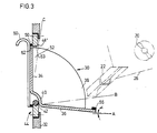
- FIG. 3 shows a further exemplary embodiment of a closure device 30.
- the parts of the closure device 30 which are the same in FIGS. 2 and 3 are identified by the same reference numbers.
- the rear wall and the front wall form an inwardly curved bearing 40 (FIG. 3) or a bead 41 (FIG. 2).
- the bearing 40 sits on a - bead 42 of a frame 44 a rectangular shaped, while the bead 41 on a support 43 of the frame is seated 44th
- the frame 44 is equipped with a rectangular flange 46, which is detachably connected to the rear wall 32 of the driver's cab 16 via screw bolts 47 (see FIG. 2).
- FIG. 2 shows a further exemplary embodiment of a closure device 30.
- the parts of the closure device 30 which are the same in FIGS. 2 and 3 are identified by the same reference numbers.
- the bead 42 is fastened to the flange 46 ′, which can also be releasably connected to the rear wall 32.
- the upper part of the frame 44 according to FIG. 2 is equipped with an inclined web 48 which extends into the interior of the collecting container 18.
- the end of the web 48 lying in the collecting container 18 is rolled up a little and serves to receive a seal 50.
- the front wall 34 rests with its upper end against the seal 50 and in this way closes the passage opening 52 provided in the rear wall 32
- the rear wall 36 likewise has a seal 56 in the region of its upper edge 54, which comes to rest in the position C of the closure device 30 against the inner end of the web 48 and in this way closes the passage opening 52 again.
- the seal 56 can also be attached to the web 48.
- FIG. 3 is also formed from a front wall 34 and a rear wall 36 which are connected to one another by left and right side walls 38.
- the locking device 30 also rests in the frame 44, which runs in the same vertical plane as the rear wall 32 of the driver's cab 16.
- the rear wall 36 forms, according to FIGS. 2 and 3, with the standing surface of the harvesting machine or with the horizontal an acute angle a which is open towards the front and which is advantageously greater than the angle of repose of the crop delivered from the conveying device 22, so that it can slip when it hits the rear wall 36 and reaches the collecting container 18. If the closure device 30 is pivoted forward and the rear wall 36 thereby comes into position B, the crop can be picked up from the conveying device 22 via the rear wall 36 and held in the closure device 30.
- the front wall 34 protrudes a little into the interior of the driver's cab 16, so that the operator can remove crop from the locking device 30 without further notice.
- the rear wall 36 lies with its seal 56 against the inside of the frame 44 or against the edge of the web 48 and thus seals the driver's cab 16 against the collecting container 18. Since the passage opening 52 is always closed by means of the closure device 30 in position C and in position A, the pressure in the driver's cabin, which is slightly below atmospheric pressure when using an air conditioning system, can be maintained.
- the closure device 30 thus fulfills two functions in a simple manner. On the one hand, it serves to completely seal the passage opening 52 in the rear wall 32 of the driver's cab, and on the other hand, it can be used to easily control the harvested crop discharged from the egg conveyor, so that the operator does not have to wait until the collecting container 18 has filled with harvested crop to then remove the crop from the collection container.
- the front wall 34 is equipped in the upper region with a grip bar 60, which can consist, for example, of a U-profile.
- the upper edge 62 of the front wall 34 is at a distance from the upper edge 63 of the flange 46 '(FIG. 3), so that the closure device 30 can be raised until the bearing 40 releases the bead 42 or the bead 41 the carrier 43 and thus the closure device can be removed from the passage opening 52.
Landscapes
- Life Sciences & Earth Sciences (AREA)
- Environmental Sciences (AREA)
- General Physics & Mathematics (AREA)
- Immunology (AREA)
- Chemical & Material Sciences (AREA)
- Analytical Chemistry (AREA)
- Biochemistry (AREA)
- General Health & Medical Sciences (AREA)
- Physics & Mathematics (AREA)
- Health & Medical Sciences (AREA)
- Pathology (AREA)
- Hydrology & Water Resources (AREA)
- Threshing Machine Elements (AREA)
- Harvesting Machines For Root Crops (AREA)
- Harvester Elements (AREA)
- Harvesting Machines For Specific Crops (AREA)
Claims (9)
Priority Applications (5)
| Application Number | Priority Date | Filing Date | Title |
|---|---|---|---|
| DE8484113448T DE3473804D1 (en) | 1984-11-07 | 1984-11-07 | Locking device for the storage tank of a harvester |
| EP84113448A EP0180660B1 (fr) | 1984-11-07 | 1984-11-07 | Dispositif de fermeture pour le réservoir d'une moissonneuse |
| US06/794,825 US4663978A (en) | 1984-11-07 | 1985-11-01 | Clean grain sampler for a combine harvester |
| BR8505558A BR8505558A (pt) | 1984-11-07 | 1985-11-06 | Mecanismo de amostragem de grao limpo aperfeicoado para combinada(ceifadeira/trilhadeira)auto-propulsionada |
| CA000494664A CA1254753A (fr) | 1984-11-07 | 1985-11-06 | Echantillonneur de grain nettoye sur moissonneuse-batteuse |
Applications Claiming Priority (1)
| Application Number | Priority Date | Filing Date | Title |
|---|---|---|---|
| EP84113448A EP0180660B1 (fr) | 1984-11-07 | 1984-11-07 | Dispositif de fermeture pour le réservoir d'une moissonneuse |
Publications (2)
| Publication Number | Publication Date |
|---|---|
| EP0180660A1 EP0180660A1 (fr) | 1986-05-14 |
| EP0180660B1 true EP0180660B1 (fr) | 1988-09-07 |
Family
ID=8192273
Family Applications (1)
| Application Number | Title | Priority Date | Filing Date |
|---|---|---|---|
| EP84113448A Expired EP0180660B1 (fr) | 1984-11-07 | 1984-11-07 | Dispositif de fermeture pour le réservoir d'une moissonneuse |
Country Status (5)
| Country | Link |
|---|---|
| US (1) | US4663978A (fr) |
| EP (1) | EP0180660B1 (fr) |
| BR (1) | BR8505558A (fr) |
| CA (1) | CA1254753A (fr) |
| DE (1) | DE3473804D1 (fr) |
Cited By (2)
| Publication number | Priority date | Publication date | Assignee | Title |
|---|---|---|---|---|
| EP0313523A1 (fr) * | 1987-09-25 | 1989-04-26 | FIATGEOTECH - TECNOLOGIE PER LA TERRA S.p.A. | Moissonneuse-batteuse équipée d'un dispositif de contrôle du retour acheminé vers le batteur |
| DE4127154A1 (de) * | 1991-08-16 | 1993-02-18 | Deere & Co | Entnahmevorrichtung fuer eine gutmenge |
Families Citing this family (11)
| Publication number | Priority date | Publication date | Assignee | Title |
|---|---|---|---|---|
| DE4125228C2 (de) * | 1991-07-30 | 1995-02-02 | Brunke Franz | Vorrichtung zur in-line-Probenahme und zur optischen Messung von Materialeigenschaften eines strömenden Fluids |
| US5604996A (en) * | 1995-08-15 | 1997-02-25 | The Gsi Group | Grain sampler and method for batch grain dryer |
| DE19744485A1 (de) * | 1997-10-09 | 1999-04-15 | Claas Selbstfahr Erntemasch | Vorrichtung zur Feuchtemessung in Erntemaschinen |
| US5974900A (en) * | 1998-02-11 | 1999-11-02 | Kalidindi; Sanyasi R. | Manually operated stream sampling device and method |
| US6119531A (en) * | 1999-08-03 | 2000-09-19 | Case Corporation | Crop sampling system |
| US6532836B1 (en) | 2001-06-08 | 2003-03-18 | Lynn Payne | Grain bin probe port and sampling method |
| DE10230475A1 (de) * | 2002-07-06 | 2004-01-15 | Deere & Company, Moline | Vorrichtung zur Entnahme von Proben |
| DE102008001783A1 (de) * | 2008-05-15 | 2009-11-19 | Deere & Company, Moline | Messanordnung zur Bestimmung der Inhaltsstoffe einer aus einem Erntegutstrom entnommenen Probe |
| US8082809B2 (en) * | 2009-10-08 | 2011-12-27 | Pioneer Hi-Bred International, Inc. | Combine harvester and associated method for selectively gathering grain test data |
| EP2768298B1 (fr) | 2011-10-21 | 2017-11-22 | Pioneer Hi-Bred International, Inc. | Moissonneuse-batteuse et procédé associé de récolte du grain |
| US12656226B1 (en) | 2022-09-24 | 2026-06-16 | Jeffrey D. Gamble | Grain sample apparatus |
Family Cites Families (11)
| Publication number | Priority date | Publication date | Assignee | Title |
|---|---|---|---|---|
| FR949394A (fr) * | 1947-07-16 | 1949-08-29 | Vidoir basculant à obturation constante | |
| FR1052186A (fr) * | 1952-03-07 | 1954-01-21 | Vide-ordures basculant | |
| US3253470A (en) * | 1964-01-06 | 1966-05-31 | Platzer | Flow sampling of cereal products and similar aggregates |
| US3474675A (en) * | 1966-12-05 | 1969-10-28 | Edna E Strand | Liquid sampler |
| US3735641A (en) * | 1970-10-05 | 1973-05-29 | Sherritt Gordon Mines Ltd | Diverting and sampling gate |
| GB1464491A (en) * | 1974-04-23 | 1977-02-16 | Polysius Ag | Sampling device |
| FR2342917A1 (fr) * | 1976-03-04 | 1977-09-30 | Toy Rene | Dispositif de division et de deviation d'un flux de produit granuleux |
| US4026155A (en) * | 1976-05-20 | 1977-05-31 | John Abraham Joseph | Conveyor sampler |
| FR2484337A1 (fr) * | 1980-02-18 | 1981-12-18 | Valeo | Dispositif pour la commande d'un appareil de chauffage et de degivrage de vehicule automobile |
| US4393704A (en) * | 1981-05-04 | 1983-07-19 | Richard Bartko | Grain loss sampling device |
| US4574645A (en) * | 1984-08-09 | 1986-03-11 | James River-Norwalk, Inc. | Apparatus for sampling particulate material |
-
1984
- 1984-11-07 EP EP84113448A patent/EP0180660B1/fr not_active Expired
- 1984-11-07 DE DE8484113448T patent/DE3473804D1/de not_active Expired
-
1985
- 1985-11-01 US US06/794,825 patent/US4663978A/en not_active Expired - Fee Related
- 1985-11-06 BR BR8505558A patent/BR8505558A/pt unknown
- 1985-11-06 CA CA000494664A patent/CA1254753A/fr not_active Expired
Cited By (4)
| Publication number | Priority date | Publication date | Assignee | Title |
|---|---|---|---|---|
| EP0313523A1 (fr) * | 1987-09-25 | 1989-04-26 | FIATGEOTECH - TECNOLOGIE PER LA TERRA S.p.A. | Moissonneuse-batteuse équipée d'un dispositif de contrôle du retour acheminé vers le batteur |
| DE4127154A1 (de) * | 1991-08-16 | 1993-02-18 | Deere & Co | Entnahmevorrichtung fuer eine gutmenge |
| EP0528309A1 (fr) * | 1991-08-16 | 1993-02-24 | Deere & Company | Extraction de prélèvement d'un échantillon de produit |
| US5269724A (en) * | 1991-08-16 | 1993-12-14 | Deere & Company | Arrangement for obtaining grain samples |
Also Published As
| Publication number | Publication date |
|---|---|
| EP0180660A1 (fr) | 1986-05-14 |
| DE3473804D1 (en) | 1988-10-13 |
| CA1254753A (fr) | 1989-05-30 |
| US4663978A (en) | 1987-05-12 |
| BR8505558A (pt) | 1986-08-12 |
Similar Documents
| Publication | Publication Date | Title |
|---|---|---|
| EP0142763B1 (fr) | Dispositif de coupe et de vidage pour sacs avec filtre collecteur de dépoussiérage | |
| DE2217350A1 (de) | Rasenmaeher | |
| EP0180660A1 (fr) | Dispositif de fermeture pour le réservoir d'une moissonneuse | |
| DE69514240T2 (de) | Vorrichtung und Verfahren zum Mischen von Futter | |
| EP0205854B1 (fr) | Dispositif de transport pour remorque agricole chargeuse | |
| DE29520278U1 (de) | Containerfahrzeug mit Ladeeinrichtung | |
| DE2819236A1 (de) | Vorrichtung zum empfangen zerbrechlicher bzw. anstossbarer objekte | |
| DE2309232A1 (de) | Vorrichtung zum entleeren von behaeltern, beispielsweise muellgefaessen, in eine einschuettoeffnung | |
| DE29805854U1 (de) | Container-Entleerungsfahrzeug zum Kippentleeren von Müll aus Containern unterschiedlichen Typs | |
| EP1852013B1 (fr) | Dispositif de retour destiné à déplacer des troncs d'arbres | |
| DE3326484C2 (fr) | ||
| DE69000736T2 (de) | Anordnung zum laden und entladen von mindestens zwei arten von abfallmaterialien. | |
| DE4331191A1 (de) | Kraftfahrzeug zum Transport von in Sammelbehältern gesammeltem Feststoffmaterial | |
| DE29615226U1 (de) | Abfallsammelfahrzeug | |
| DE1481446A1 (de) | Vorrichtung zum Entnehmen und Abgeben von Futterportionen,insbesondere aus Fahrsilos,Mieten od.dgl.,an z.B. eine Futterstelle | |
| EP0436755B1 (fr) | Apparail pour le nettoyage et le coupe de betteraves ou similaires | |
| DE955936C (de) | Fuell- und Wiegemaschine fuer einen oder mehrere Saecke mit ventilartigen Verschluessen | |
| DE19829905A1 (de) | Gerät zum Aufnehmen, Transportieren und Verteilen von Silagefutter | |
| DE1906198A1 (de) | Vorrichtung zur Entnahme von Proben | |
| DE4220776C1 (de) | Flachsiloschneid- und Übergabegerät | |
| DE102019008801B4 (de) | Einzugsanordnung mit Fangblech und Feldhäcksler mit Einzugsanordnung | |
| DE121273C (fr) | ||
| CH383882A (de) | Fahrzeug mit Ladeeinrichtung | |
| DE8332494U1 (de) | Sackschneide- und Entleerungsgerät mit angeschlossenem Sammelentstaubungsfilter | |
| DE1531933A1 (de) | Vorrichtung zum Abtragen und Transportieren von Futtermitteln |
Legal Events
| Date | Code | Title | Description |
|---|---|---|---|
| PUAI | Public reference made under article 153(3) epc to a published international application that has entered the european phase |
Free format text: ORIGINAL CODE: 0009012 |
|
| 17P | Request for examination filed |
Effective date: 19851023 |
|
| AK | Designated contracting states |
Kind code of ref document: A1 Designated state(s): BE DE FR GB IT SE |
|
| 17Q | First examination report despatched |
Effective date: 19870612 |
|
| ITF | It: translation for a ep patent filed | ||
| GRAA | (expected) grant |
Free format text: ORIGINAL CODE: 0009210 |
|
| AK | Designated contracting states |
Kind code of ref document: B1 Designated state(s): BE DE FR GB IT SE |
|
| PG25 | Lapsed in a contracting state [announced via postgrant information from national office to epo] |
Ref country code: SE Effective date: 19880907 |
|
| GBT | Gb: translation of ep patent filed (gb section 77(6)(a)/1977) | ||
| REF | Corresponds to: |
Ref document number: 3473804 Country of ref document: DE Date of ref document: 19881013 |
|
| ET | Fr: translation filed | ||
| PLBI | Opposition filed |
Free format text: ORIGINAL CODE: 0009260 |
|
| 26 | Opposition filed |
Opponent name: KHD AGRARTECHNIK GMBH Effective date: 19890605 |
|
| PGFP | Annual fee paid to national office [announced via postgrant information from national office to epo] |
Ref country code: GB Payment date: 19891031 Year of fee payment: 6 |
|
| PG25 | Lapsed in a contracting state [announced via postgrant information from national office to epo] |
Ref country code: GB Effective date: 19901107 |
|
| GBPC | Gb: european patent ceased through non-payment of renewal fee | ||
| PLBN | Opposition rejected |
Free format text: ORIGINAL CODE: 0009273 |
|
| STAA | Information on the status of an ep patent application or granted ep patent |
Free format text: STATUS: OPPOSITION REJECTED |
|
| 27O | Opposition rejected |
Effective date: 19910614 |
|
| PGFP | Annual fee paid to national office [announced via postgrant information from national office to epo] |
Ref country code: FR Payment date: 19921116 Year of fee payment: 9 |
|
| PGFP | Annual fee paid to national office [announced via postgrant information from national office to epo] |
Ref country code: BE Payment date: 19921118 Year of fee payment: 9 |
|
| ITTA | It: last paid annual fee | ||
| PG25 | Lapsed in a contracting state [announced via postgrant information from national office to epo] |
Ref country code: BE Effective date: 19931130 |
|
| BERE | Be: lapsed |
Owner name: DEERE & CY Effective date: 19931130 |
|
| PG25 | Lapsed in a contracting state [announced via postgrant information from national office to epo] |
Ref country code: FR Effective date: 19940729 |
|
| REG | Reference to a national code |
Ref country code: FR Ref legal event code: ST |
|
| PGFP | Annual fee paid to national office [announced via postgrant information from national office to epo] |
Ref country code: DE Payment date: 19951214 Year of fee payment: 12 |
|
| PG25 | Lapsed in a contracting state [announced via postgrant information from national office to epo] |
Ref country code: DE Effective date: 19970801 |