EP0180722A2 - Missile - Google Patents
Missile Download PDFInfo
- Publication number
- EP0180722A2 EP0180722A2 EP85109643A EP85109643A EP0180722A2 EP 0180722 A2 EP0180722 A2 EP 0180722A2 EP 85109643 A EP85109643 A EP 85109643A EP 85109643 A EP85109643 A EP 85109643A EP 0180722 A2 EP0180722 A2 EP 0180722A2
- Authority
- EP
- European Patent Office
- Prior art keywords
- missile
- wings
- wing
- tail unit
- rest position
- Prior art date
- Legal status (The legal status is an assumption and is not a legal conclusion. Google has not performed a legal analysis and makes no representation as to the accuracy of the status listed.)
- Granted
Links
- 238000000034 method Methods 0.000 description 4
- 230000001133 acceleration Effects 0.000 description 2
- 238000011161 development Methods 0.000 description 2
- 230000018109 developmental process Effects 0.000 description 2
- 235000015842 Hesperis Nutrition 0.000 description 1
- 235000012633 Iberis amara Nutrition 0.000 description 1
- 230000000694 effects Effects 0.000 description 1
- 239000000463 material Substances 0.000 description 1
- 230000006641 stabilisation Effects 0.000 description 1
- 238000011105 stabilization Methods 0.000 description 1
- 230000000087 stabilizing effect Effects 0.000 description 1
Images


Classifications
-
- F—MECHANICAL ENGINEERING; LIGHTING; HEATING; WEAPONS; BLASTING
- F42—AMMUNITION; BLASTING
- F42B—EXPLOSIVE CHARGES, e.g. FOR BLASTING, FIREWORKS, AMMUNITION
- F42B10/00—Means for influencing, e.g. improving, the aerodynamic properties of projectiles or missiles; Arrangements on projectiles or missiles for stabilising, steering, range-reducing, range-increasing or fall-retarding
- F42B10/02—Stabilising arrangements
- F42B10/14—Stabilising arrangements using fins spread or deployed after launch, e.g. after leaving the barrel
- F42B10/20—Stabilising arrangements using fins spread or deployed after launch, e.g. after leaving the barrel deployed by combustion gas pressure, or by pneumatic or hydraulic forces
Definitions
- the invention relates to a missile according to the preamble of claim 1.
- Missiles are to be understood as rockets launched from launcher tubes as well as projectiles fired from tubular weapons which have a tail unit for stabilizing the trajectory.
- a tail unit comprising a second wing is often provided, which is arranged in front of the tail unit in the direction of flight. A particularly great effect can be achieved with this second tail unit if the wings of this tail unit protrude far beyond the diameter of the missile.
- the invention has for its object to provide a missile with a particularly effective and operationally reliable second tail.
- FIG. 1 shows a schematic representation in side view of a missile 100 with a tail unit 101 provided for the trajectory stabilization and a tail unit 102 comprising a second wing 14, which seen in the direction of flight before the l tailplane 101 is arranged.
- This second tail unit L02 enables the flight path of the missile 100 to be influenced particularly precisely in the final phase of its flight path.
- Wings 14, which are designed to project far beyond the diameter of the missile 100, are particularly effective for this purpose.
- the wings 14 of this second tail unit 102 are designed to be retractable, at least during the launch or launch process and only afterwards, but at the latest at the beginning of the final phase of the trajectory, by means explained in more detail below, in order to get into their working position.
- FIG. 2 shows a partial sectional illustration of an enlarged detailed illustration of the missile according to FIG. 1, namely the middle part at the height of the second tail unit 102.
- a wing 14 that is folded out in the working position and a wing 14 that is folded in the rest position can be seen an axially extending slot 20 arranged in the outer wall of the missile 100.
- the wings 14 are rotatably mounted about axes 21 arranged perpendicularly with respect to the longitudinal axis 103 of the missile 100.
- the opening is expediently against the direction of flight of the missile 100, so that attacking air forces support the opening process.
- Special requirements are placed on the means which transfer the wings 14 of the second tail unit 102 from the rest position into their working position.
- the means for unfolding the wings 14 comprise an inflatable body (airbag) 12, 12 'which, in the rest position of the wings 14, is folded up in a confined space essentially in the area of the longitudinal axis 103 of the missile 100 in such a way that its bearing point on the axes 21 facing end pieces of the sinks 14 recessed in the slots 20 rest on this folded body 12, 12 '.
- airbag inflatable body
- this inflatable body 12, 12 ' can be inflated by supplying gas, it preferably expanding in the radial direction and being inflatable to an essentially disk-shaped structure.
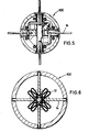
- a force acting in the radial direction is exerted on the ends of the wings 14 so that they pivot about the axes of rotation 21 and get into their working position, in which they are essentially perpendicular to the Stand longitudinal axis 103 of the missile 100.
- Reference number 12 denotes the inflatable body in the folded state; Reference number 12 'the inflated state.
- a high-tension gaseous medium for acting on the body 12, 12 ' is carried in a compressed gas container 3 which is connected to the inflatable body 12, 12' via gas channels 4, 6 with the interposition of an optionally electrically remote-controlled pressure reducing valve 5.
- the compressed gas container 3 is closed by a gas-tight closure 2.
- This closure 2 is removed in order to initiate the opening process of the wings 14, for example by means of a pyrotechnic primer 1.
- high-tension gas for the purpose of unfolding the wing 14 acts on the inflatable body 12, 12 'and gives it the shape clearly recognizable in FIG. 4, a fuse must first be removed which locks the wing 14 in the rest position within the axial slot 20.
- This fuse consists of a slide 7, which is slidably mounted in the gas channel 6 in the direction of the longitudinal axis 103 and which carries a cup-shaped retaining disk 8, which engages with its side wall 8 'in a recess 23 arranged in the outer edge 22 of the wing 14.
- gas flowing out of the compressed gas container 3 after removal of the closure 2 reaches the gas channel 6 via the gas channel 4 and the pressure reducing valve 5 and moves the slide 7 so far in the direction of flight along the axis 103 that the side wall 8 'of the cup-shaped holding disk 8 disengages from the recess 23 of the wing 14 and thereby releases it.
- the movement of the slide 7 then opens a bore 11 in the gas channel 6, which connects it to the inflatable body 12, 12 'and enables it to be inflated by the gas pressure present in the gas channel 6. Due to the radial expansion of the inflatable body 12, 12 ', the wings 14 are swung around suddenly and thus get into their working position, in which they are locked by spring-loaded bolts 24 which engage in recesses 25 arranged in the vicinity of the axis of rotation 21 in the wing 14.
- the means provided according to the invention for unfolding the wings 14 can be accommodated in a comparatively narrow space and work even after a very long storage time even under high acceleration loads
- the wings 14 of the tail unit are arranged in the radial direction and are arranged inside the shell of the missile 100. Its end pieces facing the missile axis rest on an inflatable body 12 which is folded up in the idle state. When this inflatable body 12 is subjected to a gas pressure, it expands and pushes the wings 14 outward in the radial direction, so that they get into their working position.
- the inflatable body 12, 12 ′ consists of a gas-tight material that can withstand high pressure loads.
- a fabric-reinforced rubber cover or a cover made of a plastic is particularly suitable.
Landscapes
- Physics & Mathematics (AREA)
- Fluid Mechanics (AREA)
- Engineering & Computer Science (AREA)
- General Engineering & Computer Science (AREA)
- Aiming, Guidance, Guns With A Light Source, Armor, Camouflage, And Targets (AREA)
Applications Claiming Priority (2)
| Application Number | Priority Date | Filing Date | Title |
|---|---|---|---|
| DE3432614 | 1984-09-05 | ||
| DE19843432614 DE3432614A1 (de) | 1984-09-05 | 1984-09-05 | Flugkoerper |
Publications (3)
| Publication Number | Publication Date |
|---|---|
| EP0180722A2 true EP0180722A2 (fr) | 1986-05-14 |
| EP0180722A3 EP0180722A3 (en) | 1990-03-21 |
| EP0180722B1 EP0180722B1 (fr) | 1992-06-03 |
Family
ID=6244693
Family Applications (1)
| Application Number | Title | Priority Date | Filing Date |
|---|---|---|---|
| EP19850109643 Expired - Lifetime EP0180722B1 (fr) | 1984-09-05 | 1985-07-31 | Missile |
Country Status (4)
| Country | Link |
|---|---|
| US (1) | US4659037A (fr) |
| EP (1) | EP0180722B1 (fr) |
| DE (2) | DE3432614A1 (fr) |
| ES (1) | ES8801027A1 (fr) |
Cited By (1)
| Publication number | Priority date | Publication date | Assignee | Title |
|---|---|---|---|---|
| CN103522248A (zh) * | 2013-10-11 | 2014-01-22 | 北京航天新风机械设备有限责任公司 | 一种用于舵/翼面折叠的专用工装 |
Families Citing this family (22)
| Publication number | Priority date | Publication date | Assignee | Title |
|---|---|---|---|---|
| DE3507677A1 (de) * | 1985-03-05 | 1986-09-11 | Diehl GmbH & Co, 8500 Nürnberg | Flugkoerper mit ueberkalibrigem leitwerk |
| FR2812936A1 (fr) * | 1986-08-12 | 2002-02-15 | Aerospatiale | Missile a voilure variable |
| DE3721512C1 (de) * | 1987-06-30 | 1989-03-30 | Diehl Gmbh & Co | Flugkoerper mit ueberkalibrigem Leitwerk |
| DE3918244A1 (de) * | 1989-06-05 | 1990-12-06 | Diehl Gmbh & Co | Von einem flugkoerper wegklappbarer fluegel |
| US5120947A (en) * | 1990-03-29 | 1992-06-09 | International Totalizator Systems, Inc. | Apparatus and method for processing a ticket |
| DE4020897C2 (de) * | 1990-06-30 | 1993-11-11 | Diehl Gmbh & Co | Einrichtung zum Entriegeln und Ausschwenken der Ruderblätter eines Projektiles |
| DE4105142A1 (de) * | 1991-02-20 | 1992-08-27 | Diehl Gmbh & Co | Projektil mit ausklappbarem leitwerk |
| US5211358A (en) * | 1991-05-13 | 1993-05-18 | General Dynamics Corporation | Airfoil deployment system for missile or aircraft |
| US6073880A (en) * | 1998-05-18 | 2000-06-13 | Versatron, Inc. | Integrated missile fin deployment system |
| US6186443B1 (en) | 1998-06-25 | 2001-02-13 | International Dynamics Corporation | Airborne vehicle having deployable wing and control surface |
| DE10162136B4 (de) | 2001-12-18 | 2004-10-14 | Diehl Munitionssysteme Gmbh & Co. Kg | Aus einem Rohr zu verschießender Flugkörper mit überkalibrigem Leitwerk |
| DE10205043C5 (de) | 2002-02-07 | 2010-06-17 | Diehl Bgt Defence Gmbh & Co. Kg | Aus einem Rohr zu verschließender Flugkörper mit überkalibrigem Leitwerk |
| US7800031B2 (en) * | 2005-09-07 | 2010-09-21 | Omnitek Partners Llc | Actuators for gun-fired projectiles and mortars |
| FR2909972B1 (fr) * | 2006-12-18 | 2009-10-23 | Novadem Sarl | Aeronef a decollage vertical |
| FR2952712A1 (fr) * | 2009-11-16 | 2011-05-20 | Nexter Munitions | Corps de projectile equipe d'appendices deployables |
| DE102017009671A1 (de) * | 2016-11-03 | 2018-05-03 | Diehl Defence Gmbh & Co. Kg | Verfahren zum Abwerfen eines Flugkörpers |
| IL250433B (en) * | 2017-02-02 | 2021-01-31 | Israel Aerospace Ind Ltd | Apparatus for a vehicle |
| US11300390B1 (en) | 2018-03-05 | 2022-04-12 | Dynamic Structures And Materials, Llc | Control surface deployment apparatus and method of use |
| CN112525016A (zh) * | 2020-12-22 | 2021-03-19 | 湖北航天化学技术研究所 | 一种气体产生装置及驱动装置 |
| US12007212B2 (en) | 2021-10-08 | 2024-06-11 | Simmonds Precision Products, Inc. | Joule-Thompson cooler actuation systems |
| US12068422B2 (en) | 2021-10-08 | 2024-08-20 | Simmonds Precision Products, Inc. | Systems and methods for cooling electronics |
| CN113899265A (zh) * | 2021-10-12 | 2022-01-07 | 西安现代控制技术研究所 | 一种基于光电元件的折叠舵翼张开时间测量装置 |
Family Cites Families (11)
| Publication number | Priority date | Publication date | Assignee | Title |
|---|---|---|---|---|
| US3047257A (en) * | 1958-04-24 | 1962-07-31 | Martin Marietta Corp | Device for changing airfoil profile |
| US3633846A (en) * | 1970-05-28 | 1972-01-11 | Us Navy | Expandable aerodynamic fin |
| DE2342783C2 (de) * | 1973-08-24 | 1983-12-22 | Rheinmetall GmbH, 4000 Düsseldorf | Mit einem Leitwerk versehenes Geschoß |
| DE2518593C3 (de) * | 1975-04-26 | 1979-12-06 | Diehl Gmbh & Co, 8500 Nuernberg | Mörsergeschoß |
| SE428969B (sv) * | 1977-02-09 | 1983-08-01 | Bofors Ab | Anordning vid fenstabiliserad granat |
| US4143838A (en) * | 1977-08-22 | 1979-03-13 | The United States Of America As Represented By The Secretary Of The Navy | Folding fin assembly detent |
| US4203569A (en) * | 1977-10-17 | 1980-05-20 | Bei Electronics, Inc. | Fin and nozzle unit for a free-flight rocket |
| DE7804927U1 (de) * | 1978-02-18 | 1978-06-01 | Messerschmitt-Boelkow-Blohm Gmbh, 8000 Muenchen | Vorrichtung zum ausklappen von schwenkfluegeln |
| US4364531A (en) * | 1980-10-09 | 1982-12-21 | Knoski Jerry L | Attachable airfoil with movable control surface |
| US4478150A (en) * | 1983-01-12 | 1984-10-23 | The United States Of America As Represented By The Secretary Of The Army | Cartridge with elastic pusher cup |
| US4586681A (en) * | 1983-06-27 | 1986-05-06 | General Dynamics Pomona Division | Supersonic erectable fabric wings |
-
1984
- 1984-09-05 DE DE19843432614 patent/DE3432614A1/de not_active Withdrawn
-
1985
- 1985-07-31 DE DE8585109643T patent/DE3586163D1/de not_active Expired - Fee Related
- 1985-07-31 EP EP19850109643 patent/EP0180722B1/fr not_active Expired - Lifetime
- 1985-08-26 US US06/769,178 patent/US4659037A/en not_active Expired - Fee Related
- 1985-08-27 ES ES546443A patent/ES8801027A1/es not_active Expired
Cited By (2)
| Publication number | Priority date | Publication date | Assignee | Title |
|---|---|---|---|---|
| CN103522248A (zh) * | 2013-10-11 | 2014-01-22 | 北京航天新风机械设备有限责任公司 | 一种用于舵/翼面折叠的专用工装 |
| CN103522248B (zh) * | 2013-10-11 | 2015-08-05 | 北京航天新风机械设备有限责任公司 | 一种用于舵/翼面折叠的专用工装 |
Also Published As
| Publication number | Publication date |
|---|---|
| DE3432614A1 (de) | 1986-03-13 |
| DE3586163D1 (de) | 1992-07-09 |
| US4659037A (en) | 1987-04-21 |
| EP0180722B1 (fr) | 1992-06-03 |
| ES8801027A1 (es) | 1987-12-16 |
| EP0180722A3 (en) | 1990-03-21 |
| ES546443A0 (es) | 1987-12-16 |
Similar Documents
| Publication | Publication Date | Title |
|---|---|---|
| EP0180722A2 (fr) | Missile | |
| DE3721512C1 (de) | Flugkoerper mit ueberkalibrigem Leitwerk | |
| DE69004604T2 (de) | Leitwerkausspreizungssystem für ein Geschoss. | |
| EP0114602B1 (fr) | Missile | |
| DE69806913T2 (de) | Verfahren und vorrichtung für ein flügelstabilisiertes geschoss, das eine bodensogreduzierung hat | |
| DE69502247T2 (de) | Pyrotechnische Vorrichtung zum Abschuss von mindestens einem Geschoss | |
| DE10205043B4 (de) | Aus einem Rohr zu verschließender Flugkörper mit überkalibrigem Leitwerk | |
| DE3043805A1 (de) | Waffe oder anordnung zum abfeuern von projektilen | |
| DE2227104C2 (de) | Geschoß oder Rakete mit aufklappbarem Leitwerk | |
| DE2616209A1 (de) | Kurzbahngeschoss fuer uebungsmunition | |
| DE1123597B (de) | Klappbare Stabilisierungsflossen fuer ein aus einem Geschuetzrohr abzuschiessendes Artilleriegeschoss | |
| DE1506101A1 (de) | Vorrichtung zur einwandfreien Entfaltung von Fallschirmen | |
| EP0153444B1 (fr) | Tête de combat à charge creuse | |
| DE2400947C3 (de) | Sicherungs- und Entsicherungsvorrichtung für GeschoDzünder | |
| DE3602947C1 (en) | Sub-ammunition launching mechanism from carrier missile - has bellows, axially open at both ends, with gap between both front walls and bellows ends | |
| DE68902108T2 (de) | Vorrichtung zum oeffnen der fluegelschaefte eines geschosses. | |
| DE2039400A1 (de) | Geschosszuender | |
| EP0157112A1 (fr) | Projectile avec ailettes de stabilisation | |
| DE69106950T2 (de) | Einrichtung zum Sichern und zum Schärfen einer Munition. | |
| CH661347A5 (de) | Geschoss mit einem leitwerk aus einer anzahl sich selbst aufrichtenden fluegeln, insbesondere fuer artilleriegeschuetze. | |
| EP1321737A2 (fr) | Projectiles à empennage sur-calibré lancés à partir d'un canon | |
| DE2623582C2 (de) | Raketengeschoß mit Ausklappleitwerk und Treibspiegel | |
| DE1148913B (de) | Raketengeschoss mit Spreizleitwerk | |
| DE2635676A1 (de) | Leitwerk fuer raketen | |
| DE1950638C3 (de) | Flugkörper mit entfaltbaren Stabilisierungsflächen |
Legal Events
| Date | Code | Title | Description |
|---|---|---|---|
| PUAI | Public reference made under article 153(3) epc to a published international application that has entered the european phase |
Free format text: ORIGINAL CODE: 0009012 |
|
| AK | Designated contracting states |
Kind code of ref document: A2 Designated state(s): DE FR GB IT SE |
|
| PUAL | Search report despatched |
Free format text: ORIGINAL CODE: 0009013 |
|
| AK | Designated contracting states |
Kind code of ref document: A3 Designated state(s): DE FR GB IT SE |
|
| 17P | Request for examination filed |
Effective date: 19900219 |
|
| 17Q | First examination report despatched |
Effective date: 19910321 |
|
| GRAA | (expected) grant |
Free format text: ORIGINAL CODE: 0009210 |
|
| AK | Designated contracting states |
Kind code of ref document: B1 Designated state(s): DE FR GB IT SE |
|
| PG25 | Lapsed in a contracting state [announced via postgrant information from national office to epo] |
Ref country code: SE Effective date: 19920603 Ref country code: IT Free format text: LAPSE BECAUSE OF FAILURE TO SUBMIT A TRANSLATION OF THE DESCRIPTION OR TO PAY THE FEE WITHIN THE PRESCRIBED TIME-LIMIT;WARNING: LAPSES OF ITALIAN PATENTS WITH EFFECTIVE DATE BEFORE 2007 MAY HAVE OCCURRED AT ANY TIME BEFORE 2007. THE CORRECT EFFECTIVE DATE MAY BE DIFFERENT FROM THE ONE RECORDED. Effective date: 19920603 |
|
| GBT | Gb: translation of ep patent filed (gb section 77(6)(a)/1977) | ||
| REF | Corresponds to: |
Ref document number: 3586163 Country of ref document: DE Date of ref document: 19920709 |
|
| ET | Fr: translation filed | ||
| RAP4 | Party data changed (patent owner data changed or rights of a patent transferred) |
Owner name: RHEINMETALL GMBH |
|
| PLBE | No opposition filed within time limit |
Free format text: ORIGINAL CODE: 0009261 |
|
| STAA | Information on the status of an ep patent application or granted ep patent |
Free format text: STATUS: NO OPPOSITION FILED WITHIN TIME LIMIT |
|
| 26N | No opposition filed | ||
| PGFP | Annual fee paid to national office [announced via postgrant information from national office to epo] |
Ref country code: FR Payment date: 19930628 Year of fee payment: 9 |
|
| PGFP | Annual fee paid to national office [announced via postgrant information from national office to epo] |
Ref country code: GB Payment date: 19930729 Year of fee payment: 9 |
|
| PG25 | Lapsed in a contracting state [announced via postgrant information from national office to epo] |
Ref country code: GB Effective date: 19940731 |
|
| GBPC | Gb: european patent ceased through non-payment of renewal fee |
Effective date: 19940731 |
|
| PG25 | Lapsed in a contracting state [announced via postgrant information from national office to epo] |
Ref country code: FR Effective date: 19950331 |
|
| REG | Reference to a national code |
Ref country code: FR Ref legal event code: ST |
|
| PGFP | Annual fee paid to national office [announced via postgrant information from national office to epo] |
Ref country code: DE Payment date: 19960621 Year of fee payment: 12 |
|
| PG25 | Lapsed in a contracting state [announced via postgrant information from national office to epo] |
Ref country code: DE Free format text: LAPSE BECAUSE OF NON-PAYMENT OF DUE FEES Effective date: 19980401 |