EP0180729B1 - Connecteur enfichable à composants incorporés pour conducteur - Google Patents
Connecteur enfichable à composants incorporés pour conducteur Download PDFInfo
- Publication number
- EP0180729B1 EP0180729B1 EP85110557A EP85110557A EP0180729B1 EP 0180729 B1 EP0180729 B1 EP 0180729B1 EP 85110557 A EP85110557 A EP 85110557A EP 85110557 A EP85110557 A EP 85110557A EP 0180729 B1 EP0180729 B1 EP 0180729B1
- Authority
- EP
- European Patent Office
- Prior art keywords
- pluggable connector
- connector according
- way
- contacts
- contact
- Prior art date
- Legal status (The legal status is an assumption and is not a legal conclusion. Google has not performed a legal analysis and makes no representation as to the accuracy of the status listed.)
- Expired - Lifetime
Links
Images
Classifications
-
- H—ELECTRICITY
- H01—ELECTRIC ELEMENTS
- H01R—ELECTRICALLY-CONDUCTIVE CONNECTIONS; STRUCTURAL ASSOCIATIONS OF A PLURALITY OF MUTUALLY-INSULATED ELECTRICAL CONNECTING ELEMENTS; COUPLING DEVICES; CURRENT COLLECTORS
- H01R13/00—Details of coupling devices of the kinds covered by groups H01R12/70 or H01R24/00 - H01R33/00
- H01R13/66—Structural association with built-in electrical component
- H01R13/665—Structural association with built-in electrical component with built-in electronic circuit
- H01R13/6658—Structural association with built-in electrical component with built-in electronic circuit on printed circuit board
Definitions
- the invention relates to a multipole line connector with a component insert, the electrical connection parts of which are conductively connected to contact elements arranged in chambers of a contact carrier made of insulating material.
- the contact elements each have a conductor connection part, for example a screw terminal, and a pin-shaped or socket-shaped plug-in part.
- Such a line connector is known for example from DE-OS 33 10 067.
- the housing cover also forms the component insert carrying the intended electrical components (resistors, capacitors, light-emitting diodes, etc.).
- the invention has for its object to form a line connector according to the preamble of claim 1 such that a small footprint, simple assembly, easy replacement of the component insert or individual components and minimal effort to ensure high tightness are achieved in an economical manner.
- each contact element chamber has a pocket in whose wall opposite the contact element (for example a screw terminal) there is an inserted, for example as Supported metal spring formed connecting part and thereby rests under pressure on the contact element.
- the contact parts need not be inherently stable because of the rigid holding part. Rather, they can be made thin and therefore inexpensive, an advantage that is particularly important in the case of a large number of contacts.
- a simple and effective mounting of the contact parts is achieved by a roof part of the groove which is integral with the holding part.
- the plug contacts are circular, but at least symmetrically arranged around the axis.
- the symmetrical structure of this unit of the holding part and the use of components also allows a large reduction in type because only a single unit of this type is required for the connectors mentioned. Due to the advantageous embodiments listed in claims 7 and 8, the use of components is extremely simple and can only be inserted into the contact carrier in the unmistakably correct assignment of the contacts, which considerably simplifies handling during assembly and repairs.
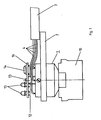
- FIG. 1 is a side view without the cover which is not essential to the invention
- FIG. 2 is an axial partial section, in which only one strand is shown for the sake of clarity
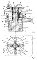
- FIG. 3 is a section running across the axis according to section line AB.
- a contact carrier 1 of the angled connector consisting of insulating material has a mounting plate 2 for fastening a cable 3, which is not shown for reasons of clarity four strands 4 and a cover made of translucent plastic, as well as a central guide pin 5 and four chambers 6, in each of which a socket 8 provided for screwing the strands 4 is arranged.
- the chambers 6 end on the plug side in openings 9 for inserting contact pins of a mating connector which can be fixed by means of a union nut 10 of the angled connector and are each expanded by a pocket 11 which is open to the plug axis.
- a plastic sleeve 12 is inserted which comprises the guide pin 5 and which is firmly connected by means of a screw 13 to a component insert in the form of a printed circuit board 16 carrying various electrical components, of which the resistor 14 and the light emitting diodes 15 are shown.
- this can also be made in one piece with the sleeve 12.
- the sleeve 12 has four evenly distributed on the outside protruding axially extending grooves 17, in each of which a galvanically connected to corresponding connections on the circuit board 16 and by means of a roof part 18 held in the groove is arranged, which is located at the bottom of the Groove 17 supports and rests under pressure on the screw terminal 7 in question.
- the guide pin 5 is not exactly cylindrical, but has an axial flat 20 on the outside.
- the inner surface of the sleeve 12 is adapted so that the component insert 16 with its connecting parts 19 can only be inserted into the contact carrier 1 in a single position, in which these connections are assigned to the correct sockets 8.
- the described cable connector is extremely easy and safe to assemble or disassemble, even with very small designs and high numbers of poles, and has minimal dimensions.
Landscapes
- Engineering & Computer Science (AREA)
- Microelectronics & Electronic Packaging (AREA)
- Connector Housings Or Holding Contact Members (AREA)
- Coupling Device And Connection With Printed Circuit (AREA)
- Multi-Conductor Connections (AREA)
- Details Of Connecting Devices For Male And Female Coupling (AREA)
Claims (8)
- Connecteur enfichable, multipolaire, à composants incorporés pour conducteurs (16) et à support de contact (1) en matière isolée, chez lequel les pièces de raccordement électriques (19) des composants incorporés pour conducteur (16) sont connectées de façon conductrice avec des éléments de contact (7, 8), placées dans les galettes (6) du support de contact,
caractérisé par le fait que les pièces de rattachement (19) des composants incorporés pour conducteurs (16) et les éléments de contact (7, 8) y appartenant sont conçus de façon à être enfichables directement. - Connecteur enfichable, conforme à la demande no 1, caractérisé par le fait que les pièces de raccordement (19) et les éléments de contact (7, 8) à l'état enfiché font ressort élastique les uns sur les autres.
- Connecteur enfichable, conforme à la demande no 2, caractérisé par le fait que les galettes (6) ont chacune une poche ouverte (11) vers l'élément de contact (7) dans laquelle une piéce de raccordement (19) peut être enfichée.
- Connecteur enfichable, conforme à la demande no 3, caractérisé par le fait que les poches (11) sont ouvertes aussi aux côtés opposés aux éléments de contact (7) et que les pièces de raccordement (19) enfichées dedans sont placées et appuyées dans les rainures (17) d'une piéce d'arrêt (12).
- Connecteur enfichable, conforme à la demande no 4, caractérisé par le fait que les pièces de raccordement (19) sont tenues préférablement par marquage de position grâce aux pièces de toiture (18) des rainures (17).
- Connecteur enfichable, conforme à une des demandes no 4 ou no 5, caractérisé par le fait que la pièce d'arrêt (18) est positionnée de façon axiale et concentrique par rapport aux éléments de contact (7, 8) et qu'elle sert comme support - préférablement rattaché fixement - aux composants incorporés pour conducteur (16).
- Connecteur enfichable, conforme à la demande no 6, caractérisé par le fait que la pièce d'arrêt (12) englobe un tenon de guidage (5) déplaçable, d'un tracé concentrique, axial et fixé au support de contact (1).
- Connecteur enfichable, conforme à la demande no 7, caractérisé par le fait que le tenon de guidage (5) et la pièce d'arrêt (12) ont respectivement à l'exterieur ou à l'intérieur une surface de guidage (20) plane, d'un tracé axial, l'une ajustée à l'autre.
Applications Claiming Priority (2)
| Application Number | Priority Date | Filing Date | Title |
|---|---|---|---|
| DE3440748 | 1984-11-08 | ||
| DE3440748A DE3440748C2 (de) | 1984-11-08 | 1984-11-08 | Leitungssteckverbinder mit Bauelementeeinsatz |
Publications (3)
| Publication Number | Publication Date |
|---|---|
| EP0180729A2 EP0180729A2 (fr) | 1986-05-14 |
| EP0180729A3 EP0180729A3 (en) | 1989-05-10 |
| EP0180729B1 true EP0180729B1 (fr) | 1992-11-11 |
Family
ID=6249754
Family Applications (1)
| Application Number | Title | Priority Date | Filing Date |
|---|---|---|---|
| EP85110557A Expired - Lifetime EP0180729B1 (fr) | 1984-11-08 | 1985-08-22 | Connecteur enfichable à composants incorporés pour conducteur |
Country Status (2)
| Country | Link |
|---|---|
| EP (1) | EP0180729B1 (fr) |
| DE (2) | DE3440748C2 (fr) |
Families Citing this family (11)
| Publication number | Priority date | Publication date | Assignee | Title |
|---|---|---|---|---|
| DE3509344A1 (de) * | 1985-03-15 | 1986-09-18 | Hirschmann Radiotechnik | Mehrpoliger leitungssteckverbinder mit bauteileeinsatz |
| DE8811471U1 (de) * | 1988-09-10 | 1988-11-10 | Robert Bosch Gmbh, 70469 Stuttgart | Koaxialer Winkelstecker |
| DE3909783C2 (de) * | 1989-03-22 | 1996-06-13 | Krone Ag | Schutzstecker für Anschlußleisten der Fernmelde- und Datentechnik |
| GB2245427A (en) * | 1990-06-21 | 1992-01-02 | Ashley & Rock Ltd | Electrical switch accessories |
| DE9104337U1 (de) * | 1991-04-10 | 1992-08-06 | Hermann Kleinhuis GmbH & Co KG, 5880 Lüdenscheid | Überspannungsschutzadapter |
| US5236098A (en) * | 1992-03-13 | 1993-08-17 | Thomas & Betts Corporation | Socket and header electrical connector assembly |
| DE4222685C2 (de) * | 1992-07-10 | 1995-08-10 | Hirschmann Richard Gmbh Co | Steckkontaktelement |
| US5238429A (en) * | 1992-09-14 | 1993-08-24 | General Motors Corporation | Electrical assembly and connector therefor |
| DE29910179U1 (de) * | 1999-06-11 | 2000-11-02 | Weidmüller Interface GmbH & Co, 32760 Detmold | Steckverbinder für elektrische Steuerungen |
| JP3603783B2 (ja) * | 2000-12-11 | 2004-12-22 | 住友電装株式会社 | コネクタ |
| DE102013110548B4 (de) | 2013-09-24 | 2025-02-06 | Phoenix Contact E-Mobility Gmbh | Steckverbinderteil mit einer Widerstandkodierung |
Family Cites Families (4)
| Publication number | Priority date | Publication date | Assignee | Title |
|---|---|---|---|---|
| DE6910610U (de) * | 1969-03-15 | 1969-07-31 | Hirschmann Radiotechnik | Elektrisches steckverbindungsteil mit austauschbaren einsaetzen |
| FR2191303B1 (fr) * | 1972-06-30 | 1980-05-09 | Fischer Artur | |
| GB1595897A (en) * | 1976-11-16 | 1981-08-19 | Lessiter N | Warning devices in electrical plugs or adaptors |
| DE3310067A1 (de) * | 1983-03-21 | 1984-09-27 | Siemens AG, 1000 Berlin und 8000 München | Steckverbinder fuer ein elektrisches geraet |
-
1984
- 1984-11-08 DE DE3440748A patent/DE3440748C2/de not_active Expired - Fee Related
-
1985
- 1985-08-22 DE DE8585110557T patent/DE3586815D1/de not_active Expired - Lifetime
- 1985-08-22 EP EP85110557A patent/EP0180729B1/fr not_active Expired - Lifetime
Also Published As
| Publication number | Publication date |
|---|---|
| DE3440748C2 (de) | 1993-12-23 |
| DE3586815D1 (de) | 1992-12-17 |
| EP0180729A3 (en) | 1989-05-10 |
| DE3440748A1 (de) | 1986-05-07 |
| EP0180729A2 (fr) | 1986-05-14 |
Similar Documents
| Publication | Publication Date | Title |
|---|---|---|
| EP1730816B1 (fr) | Adaptateur enfichable | |
| EP0180729B1 (fr) | Connecteur enfichable à composants incorporés pour conducteur | |
| DE102007003815A1 (de) | Platinen-montierte Anschlusskonstruktion | |
| EP0584481B1 (fr) | Borne de connexion multipolaire | |
| DE19939580A1 (de) | Elektrischer Steckverbinder | |
| DE102007026097B4 (de) | Steckverbinder für Leiterplatten | |
| EP4135168A1 (fr) | Dispositif interface électrique pour un moteur électrique | |
| DE2950981A1 (de) | Buchse zur senkrechten montage einer mehrere stecker aufweisenden elektronischen vorrichtung | |
| DE102006051874A1 (de) | Elektrochemischer Kondensator mit kleinem ESR und Steckverbinder | |
| DE19605083A1 (de) | Kabelanschlußeinrichtung | |
| DE3221042C2 (de) | Relaisfassung | |
| DE69902498T2 (de) | Leiterplattenrandverbinder | |
| EP1154521B1 (fr) | Connecteur et procédé de montage de connecteur | |
| DE4222685C2 (de) | Steckkontaktelement | |
| DE2303969C3 (de) | Anordnung zum elektrischen und mechanischen Verbinden von Pfosten an Steckverbindern mit Metallplatten | |
| DE4224154C1 (de) | Wasserdichte elektrische Steckverbinderanordnung | |
| WO1995020238A1 (fr) | Lampe compacte avec adaptateur | |
| EP0158122B1 (fr) | Fiche programmable | |
| DE3338779C1 (de) | Feder- oder Buchsenleiste | |
| EP4026203B1 (fr) | Connecteur encartable | |
| DE102010039957B4 (de) | Trennbuchsenanordnungen und Trennadapter mit einer Trägerplatte und einer oder mehreren darin angebrachten Trennbuchsen der Trennbuchsenanordnungen | |
| DE102021125247A1 (de) | Adapterelement | |
| DE7922314U1 (de) | Elektrische Anschlußklemme für Leiterplatten | |
| DE102018204027B4 (de) | Funkenstreckenanordnung mit Zündhilfe | |
| DE10056904B4 (de) | Verbindungsanordnung |
Legal Events
| Date | Code | Title | Description |
|---|---|---|---|
| PUAI | Public reference made under article 153(3) epc to a published international application that has entered the european phase |
Free format text: ORIGINAL CODE: 0009012 |
|
| AK | Designated contracting states |
Kind code of ref document: A2 Designated state(s): CH DE FR IT LI SE |
|
| PUAL | Search report despatched |
Free format text: ORIGINAL CODE: 0009013 |
|
| AK | Designated contracting states |
Kind code of ref document: A3 Designated state(s): CH DE FR IT LI SE |
|
| 17P | Request for examination filed |
Effective date: 19890616 |
|
| RAP1 | Party data changed (applicant data changed or rights of an application transferred) |
Owner name: RICHARD HIRSCHMANN GMBH & CO. |
|
| 17Q | First examination report despatched |
Effective date: 19901210 |
|
| GRAA | (expected) grant |
Free format text: ORIGINAL CODE: 0009210 |
|
| AK | Designated contracting states |
Kind code of ref document: B1 Designated state(s): CH DE FR IT LI SE |
|
| REF | Corresponds to: |
Ref document number: 3586815 Country of ref document: DE Date of ref document: 19921217 |
|
| ITF | It: translation for a ep patent filed | ||
| ET | Fr: translation filed | ||
| PLBE | No opposition filed within time limit |
Free format text: ORIGINAL CODE: 0009261 |
|
| STAA | Information on the status of an ep patent application or granted ep patent |
Free format text: STATUS: NO OPPOSITION FILED WITHIN TIME LIMIT |
|
| 26N | No opposition filed | ||
| EAL | Se: european patent in force in sweden |
Ref document number: 85110557.7 |
|
| PGFP | Annual fee paid to national office [announced via postgrant information from national office to epo] |
Ref country code: SE Payment date: 19950524 Year of fee payment: 11 |
|
| PGFP | Annual fee paid to national office [announced via postgrant information from national office to epo] |
Ref country code: FR Payment date: 19950828 Year of fee payment: 11 |
|
| PGFP | Annual fee paid to national office [announced via postgrant information from national office to epo] |
Ref country code: CH Payment date: 19951016 Year of fee payment: 11 |
|
| PG25 | Lapsed in a contracting state [announced via postgrant information from national office to epo] |
Ref country code: SE Effective date: 19960823 |
|
| PG25 | Lapsed in a contracting state [announced via postgrant information from national office to epo] |
Ref country code: LI Effective date: 19960831 Ref country code: CH Effective date: 19960831 |
|
| REG | Reference to a national code |
Ref country code: CH Ref legal event code: PL |
|
| PG25 | Lapsed in a contracting state [announced via postgrant information from national office to epo] |
Ref country code: FR Effective date: 19970430 |
|
| EUG | Se: european patent has lapsed |
Ref document number: 85110557.7 |
|
| REG | Reference to a national code |
Ref country code: FR Ref legal event code: ST |
|
| PGFP | Annual fee paid to national office [announced via postgrant information from national office to epo] |
Ref country code: DE Payment date: 20040805 Year of fee payment: 20 |