EP0180779A2 - Vorrichtung zum Halten von Kastenteilen beim Befestigen von diesen an einer Kette von trennbaren Reissverschlüssen mit Einsteck- und Kastenstiften - Google Patents
Vorrichtung zum Halten von Kastenteilen beim Befestigen von diesen an einer Kette von trennbaren Reissverschlüssen mit Einsteck- und Kastenstiften Download PDFInfo
- Publication number
- EP0180779A2 EP0180779A2 EP85112607A EP85112607A EP0180779A2 EP 0180779 A2 EP0180779 A2 EP 0180779A2 EP 85112607 A EP85112607 A EP 85112607A EP 85112607 A EP85112607 A EP 85112607A EP 0180779 A2 EP0180779 A2 EP 0180779A2
- Authority
- EP
- European Patent Office
- Prior art keywords
- box
- slide block
- recess
- holder
- cam
- Prior art date
- Legal status (The legal status is an assumption and is not a legal conclusion. Google has not performed a legal analysis and makes no representation as to the accuracy of the status listed.)
- Granted
Links
Images


Classifications
-
- A—HUMAN NECESSITIES
- A44—HABERDASHERY; JEWELLERY
- A44B—BUTTONS, PINS, BUCKLES, SLIDE FASTENERS, OR THE LIKE
- A44B19/00—Slide fasteners
- A44B19/24—Details
- A44B19/40—Connection of separate, or one-piece, interlocking members to stringer tapes; Reinforcing such connections, e.g. by stitching
-
- A—HUMAN NECESSITIES
- A44—HABERDASHERY; JEWELLERY
- A44B—BUTTONS, PINS, BUCKLES, SLIDE FASTENERS, OR THE LIKE
- A44B19/00—Slide fasteners
- A44B19/42—Making by processes not fully provided for in one other class, e.g. B21D53/50, B21F45/18, B22D17/16, B29D5/00
- A44B19/60—Applying end stops upon stringer tapes
-
- A—HUMAN NECESSITIES
- A44—HABERDASHERY; JEWELLERY
- A44B—BUTTONS, PINS, BUCKLES, SLIDE FASTENERS, OR THE LIKE
- A44B19/00—Slide fasteners
- A44B19/42—Making by processes not fully provided for in one other class, e.g. B21D53/50, B21F45/18, B22D17/16, B29D5/00
- A44B19/62—Assembling sliders in position on stringer tapes
- A44B19/64—Slider holders for assemblage of slide fasteners
-
- Y—GENERAL TAGGING OF NEW TECHNOLOGICAL DEVELOPMENTS; GENERAL TAGGING OF CROSS-SECTIONAL TECHNOLOGIES SPANNING OVER SEVERAL SECTIONS OF THE IPC; TECHNICAL SUBJECTS COVERED BY FORMER USPC CROSS-REFERENCE ART COLLECTIONS [XRACs] AND DIGESTS
- Y10—TECHNICAL SUBJECTS COVERED BY FORMER USPC
- Y10T—TECHNICAL SUBJECTS COVERED BY FORMER US CLASSIFICATION
- Y10T29/00—Metal working
- Y10T29/51—Plural diverse manufacturing apparatus including means for metal shaping or assembling
- Y10T29/5101—Slide fastener or slide fastener element
-
- Y—GENERAL TAGGING OF NEW TECHNOLOGICAL DEVELOPMENTS; GENERAL TAGGING OF CROSS-SECTIONAL TECHNOLOGIES SPANNING OVER SEVERAL SECTIONS OF THE IPC; TECHNICAL SUBJECTS COVERED BY FORMER USPC CROSS-REFERENCE ART COLLECTIONS [XRACs] AND DIGESTS
- Y10—TECHNICAL SUBJECTS COVERED BY FORMER USPC
- Y10T—TECHNICAL SUBJECTS COVERED BY FORMER US CLASSIFICATION
- Y10T29/00—Metal working
- Y10T29/53—Means to assemble or disassemble
- Y10T29/53291—Slide fastener
- Y10T29/53296—Means to assemble stop onto stringer
Definitions
- the known box attaching apparatus having such swingable box holder is complex in structure because the box holder includes a box-gripper mechanism, a gripper actuating mechanism, and a holder rocking mechanism. Furthermore, the swingable box holder occupies a relatively large space for its operation and requires a tedious handling. With these difficulties, the known apparatus fails to meet a desire of providing a compact box attaching apparatus.
- the present invention seeks to provide an apparatus for holding a box in the process of attaching the box to a box pin on a separable slide fastener chain, the apparatus being simple in construction, reliable in operation, and compact and hence occupying a relatively small space for its operation.
- an apparatus for holding a box in the process of attaching the box to a box pin on an end of a separable slide fastener fed along a fed path comprising: a frame; a box holder movably mounted on said frame-and movable between a box attaching position located in the feed path of the separable slide fastener chain and a box receiving position remote from said box attaching position; and means for moving said box holder, characterized in that said box holder is vertically reciprocably disposed and includes a pair of spaced first and second portions defining therebetween a recessed portion, said first portion having a recess for receiving the box, said second portion having a cam facing said recessed portion, that a slide block is vertically movably disposed in said recessed portion, that a clamp finger is pivotably mounted on said slide block and has free end portion engageable with the box to releasably retaining the latter in said recess, and a portion engageable with said cam to cause said clamp finger
- the elongated separable slide fastener chain, generally indicated by the numeral 12 is composed of a pair of slide fastener stringers 13, 13 each comprising a stringer tape 14 and a row of coupl ing elements 15 mounted on and along an inner longitudinal edge of the stringer tape 14.
- the separable slide fastener chain 12 has a plurality of longitudinally spaced, film- reinforced element-free portions 16 extending transversely across the stringer tapes 13.
- An insertion pin 17 and a box pin 18 are attached to the inner confronting edges of the stringer tapes 14 at each of the element-free portions 16.
- a slider 19 is slidably mounted on the rows of coupling elements 15 to interconnect the stringer tapes 13, 13 and is positioned between two adjacent element-free portions 16.
- a box 20 is attached to the box pin 18 by the apparatus 11 with the insertion pin 17 received in the box 20.
- Each of the element-free portions 16 has a pair of confronting U-shaped recesses 21, 21 ( Figure 8) defined at the inner longitudinal edges of the stringer tapes 14, 14 adjacent to the insertion and box pins 17, 18.
- the recesses 21, 21 serve to facilitate insertion of the pins 17, 18 into the box 20.
- the elongate slide fastener chain 12 thus assembled is cut off across the element-free portions 16 along a transverse line 22 at the end of each box 20 which faces into the U-shaped recesses 21, 21, thereby producing an individual separable slide fastener 23 as shown in Figure 7B.
- the elongate slide fastener chain 12 will be longitudinally fed along a feed path through the apparatus 11 in such a direction that the end of each box 20 facing into the U-shaped recesses 21, 21 is the leading end and the box end from which the insertion and box pins 17, 18 are introduced into the box 20 is the trailing end.
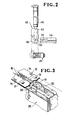
- the apparatus 11 includes an elongate box holder 25 vertically disposed below a feed.path of the separable slide fastener chain 12.
- the box holder 25 is slidably supported on a horizontal frame 26 and is connected to the piston rod of a first fluid actuator, such as an air cylinder 27 so as to reciprocate between an upper box attaching position (indicated by phantom lines) located in the feed path, and a lower box receiving position where boxes 20 are supplied one at a time to the box holder 25, as described below.
- a first fluid actuator such as an air cylinder 27
- the box holder 25 has an upper portion composed of a front portion 28 and a rear portion 29 separated by a recessed portion 30 defined therebetween.
- the front portion-28 has in its top surface a recess 31 for receiving a box 20.
- the box holder 25 further includes a clamp finger 32 movably disposed in the recessed portion 30 for holding the box 20 stably in the recess 31 against displacement therefrom.
- the clamp finger 32 is pivoted at its lower end on a pin 33 secured to an upper portion of a slide block 34 slidably mounted in the recessed portion 30 from the bottom of the latter.
- the slide block 34 is urged downwardly by a compression coil spring 35 acting between the slide block 34 and the rear portion 29 of the box holder 25.
- a torsion spring 36 is supported on the pin 33 and acts between the slide block 34 and the clamp finger 32 to urge the latter clockwise (Figure 1) toward the rear portion 29, thereby releasing the box 20.
- the clamp finger 32 has in its rear surface a recessed cam follower portion 37 engageable with a cam 38 which projects from the rear portion 29 into the recessed portion 30 of the box holder 25, the cam 38 having an upper sloped cam surface.
- a second fluid actuator such as an air cylinder 39 is mounted on the lower end of the box holder 25 and has a piston rod 40 extending longitudinally in the box holder 25 and having an upper free end disposed in the recessed portion 30 below the slide block 34.
- the compression coil spring 35 is stronger than the torsion spring 36 so that the slide block 34 is normally held in a lowermost position shown in Figure 6 where the cam 38 is out of engagement with the recessed cam follower portion 37 and urges the clamp finger 32 counterclockwise against the bias of the torsion spring 36 until the clamp finger 32 abuts against the front portion 28.
- the clamp finger 32 has a box-retaining free end portion 41 projectable into the box-receiving recessed portion 31 when the slide block 34 is in the lowermost position.
- the boxes 20 are supplied one at a time to the box holder 25 by a box feed mechanism 42, as shown in Figure 2.
- the box feed mechanism 42 comprises a gripper 43 for folding a box 20 supplied from a chute 44 and placing the box 20 in the recess 31 of the box holder 25 while the latter is at rest in the box receiving position.
- the gripper 43 includes a grip finger 45 pivotably movable to hold the box 20 on the gripper 43 and to release the box 20 from the gripper 43, and an air cylinder 46 for reciprocating the gripper 43 between a loading position located adjacent to the discharge end of the chute 44, and an unloading position located immediately above the box-receiving position of the box holder 25.
- the air cylinder 27 is actuated to extend its piston rod for lowering the box holder 25 to its box-receiving position. Then the air cylinder 39 is actuated to extend the piston rod 40 whereupon the clamp finger 32 is angularly moved away from the front part 28 to open the recess 31 ( Figure 5).
- the gripper 43 with the box 20 retained thereon by the grip finger 45 is moved to the unloading position by the air cylinder 46. Then, the grip finger 45 is actuated to release the box 20 therefrom into the recess 31 of the box holder 25.
- the air cylinder 39 is actuated to lower the piston rod 40 whereupon the slide block 34 is lowered by the force of the spring 35, during which time the clamp jaw 32 is turned counterclockwise ( Figure 4) until the box retaining end portion 41 abuts the box 20.
- the slide block 42 is further moved downwardly by a distance L until the clamp finger 32 impinges against the front portion 28 of the box holder 25.
- Such further donward movement of the slide block 34 i.e.
- a sensor 47 such as a photoelectric switch or a metal sensing proximity switch.
- the sensor 47 Upon detection of the non-presence of the box 20, the sensor 47 sends an electric signal to a control unit (not shown) to automatically recover such improper condition.
- the box attachment apparatus 11 further includes a punch 48 vertically movably mounted on the frame 26 in alignment with the box holder 25 for attaching the box 20 to the box pin 18 ( Figure 3) on the slide fastener chain 12.
- the punch 48 has on its lower surface a central recess (not designated) for receiving the clamp finger 32, and a projection 49 for plastically deforming the material of the box 20 and the box pin 18 to clinch them together.
- the box 20 thus clinched has a rectangular recess 50 ( Figure 8) which forms a complementary locking jaw interlocking the box 20 and the box pin 18.
- the box 20 and box pin 18 may be made of a synthetic resin, in which instance an ultrasonic horn is employed instead of the punch 48 so as to weld the box 20 and box pin 18.
- the box 20 may be snapped over the box pin 18 as the slide fastener chain 12 is threaded through the box 20 while the latter is retained in the feed path of the slide fastener chain.
- the punch 48 can be omitted.
Landscapes
- Slide Fasteners (AREA)
- Container Filling Or Packaging Operations (AREA)
- Package Closures (AREA)
Applications Claiming Priority (2)
| Application Number | Priority Date | Filing Date | Title |
|---|---|---|---|
| JP1984150779U JPH0111063Y2 (de) | 1984-10-05 | 1984-10-05 | |
| JP150779/84U | 1984-10-05 |
Publications (3)
| Publication Number | Publication Date |
|---|---|
| EP0180779A2 true EP0180779A2 (de) | 1986-05-14 |
| EP0180779A3 EP0180779A3 (en) | 1988-09-28 |
| EP0180779B1 EP0180779B1 (de) | 1991-01-16 |
Family
ID=15504244
Family Applications (1)
| Application Number | Title | Priority Date | Filing Date |
|---|---|---|---|
| EP85112607A Expired - Lifetime EP0180779B1 (de) | 1984-10-05 | 1985-10-04 | Vorrichtung zum Halten von Kastenteilen beim Befestigen von diesen an einer Kette von trennbaren Reissverschlüssen mit Einsteck- und Kastenstiften |
Country Status (13)
| Country | Link |
|---|---|
| US (1) | US4653184A (de) |
| EP (1) | EP0180779B1 (de) |
| JP (1) | JPH0111063Y2 (de) |
| KR (1) | KR870001355Y1 (de) |
| AU (1) | AU556077B2 (de) |
| BR (1) | BR8504966A (de) |
| CA (1) | CA1242569A (de) |
| DE (1) | DE3581368D1 (de) |
| ES (1) | ES8608833A1 (de) |
| GB (1) | GB2165884B (de) |
| HK (1) | HK60790A (de) |
| MY (1) | MY101333A (de) |
| SG (1) | SG58790G (de) |
Cited By (1)
| Publication number | Priority date | Publication date | Assignee | Title |
|---|---|---|---|---|
| EP0657120A1 (de) * | 1993-11-18 | 1995-06-14 | Ykk Corporation | Vorrichtung zur Einführung von Zuglaschen von verdeckten Reissverschlussen und Vorrichtung zur Fertigstellung von verdeckten Reissverschlüssen |
Families Citing this family (1)
| Publication number | Priority date | Publication date | Assignee | Title |
|---|---|---|---|---|
| JP3621014B2 (ja) * | 1999-04-22 | 2005-02-16 | Ykk株式会社 | スライドファスナー用チェンおよびその末端成形方法ならびに末端成形装置 |
Family Cites Families (6)
| Publication number | Priority date | Publication date | Assignee | Title |
|---|---|---|---|---|
| US3714698A (en) * | 1970-03-14 | 1973-02-06 | Yoshida Kogyo Kk | Method and machine for assembling slide fasteners of separable type |
| JPS5550306A (en) * | 1978-10-05 | 1980-04-12 | Yoshida Kogyo Kk | Method and apparatus for attaching stopper for slide fastener |
| JPS5942905Y2 (ja) * | 1980-08-08 | 1984-12-18 | ワイケイケイ株式会社 | スライダ−保持装置 |
| JPS581315U (ja) * | 1981-06-29 | 1983-01-06 | ワイケイケイ株式会社 | スライドファスナ−のストリンガ−開金具取付器 |
| JPS5911806A (ja) * | 1982-07-10 | 1984-01-21 | ワイケイケイ株式会社 | 開離嵌挿具付スライドファスナに棒金具を取付ける装置 |
| JPS5977410U (ja) * | 1982-11-17 | 1984-05-25 | ワイケイケイ株式会社 | スライドフアスナ−のスライダ保持装置 |
-
1984
- 1984-10-05 JP JP1984150779U patent/JPH0111063Y2/ja not_active Expired
-
1985
- 1985-09-24 GB GB08523537A patent/GB2165884B/en not_active Expired
- 1985-09-26 KR KR2019850012535U patent/KR870001355Y1/ko not_active Expired
- 1985-09-27 AU AU47953/85A patent/AU556077B2/en not_active Ceased
- 1985-10-02 US US06/783,142 patent/US4653184A/en not_active Expired - Lifetime
- 1985-10-03 CA CA000492113A patent/CA1242569A/en not_active Expired
- 1985-10-04 ES ES85547593A patent/ES8608833A1/es not_active Expired
- 1985-10-04 BR BR8504966A patent/BR8504966A/pt not_active IP Right Cessation
- 1985-10-04 DE DE8585112607T patent/DE3581368D1/de not_active Expired - Lifetime
- 1985-10-04 EP EP85112607A patent/EP0180779B1/de not_active Expired - Lifetime
-
1987
- 1987-08-12 MY MYPI87001310A patent/MY101333A/en unknown
-
1990
- 1990-07-17 SG SG587/90A patent/SG58790G/en unknown
- 1990-08-09 HK HK607/90A patent/HK60790A/xx not_active IP Right Cessation
Cited By (2)
| Publication number | Priority date | Publication date | Assignee | Title |
|---|---|---|---|---|
| EP0657120A1 (de) * | 1993-11-18 | 1995-06-14 | Ykk Corporation | Vorrichtung zur Einführung von Zuglaschen von verdeckten Reissverschlussen und Vorrichtung zur Fertigstellung von verdeckten Reissverschlüssen |
| US5501000A (en) * | 1993-11-18 | 1996-03-26 | Ykk Corporation | Slider inserting apparatus for concealed slide fastener and concealed slide fastener finishing machine |
Also Published As
| Publication number | Publication date |
|---|---|
| ES8608833A1 (es) | 1986-09-01 |
| EP0180779A3 (en) | 1988-09-28 |
| DE3581368D1 (de) | 1991-02-21 |
| BR8504966A (pt) | 1986-07-22 |
| MY101333A (en) | 1991-09-05 |
| JPS6166510U (de) | 1986-05-07 |
| GB2165884B (en) | 1988-06-15 |
| GB2165884A (en) | 1986-04-23 |
| ES547593A0 (es) | 1986-09-01 |
| HK60790A (en) | 1990-08-17 |
| KR870001355Y1 (ko) | 1987-04-08 |
| GB8523537D0 (en) | 1985-10-30 |
| SG58790G (en) | 1990-09-07 |
| JPH0111063Y2 (de) | 1989-03-30 |
| AU4795385A (en) | 1986-04-10 |
| AU556077B2 (en) | 1986-10-23 |
| US4653184A (en) | 1987-03-31 |
| CA1242569A (en) | 1988-10-04 |
| KR860004280U (ko) | 1986-05-01 |
| EP0180779B1 (de) | 1991-01-16 |
Similar Documents
| Publication | Publication Date | Title |
|---|---|---|
| EP0412420B1 (de) | Verfahren und Vorrichtung zur Zusammenfassung eines Schiebers an eine Zuglasche | |
| CA1257076A (en) | Apparatus for assembling a pair of fastener elements | |
| EP0268812B1 (de) | Vorrichtung zum Herstellen von Reissverschlüssen | |
| EP0172546B1 (de) | Verfahren und Vorrichtung zur Herstellung gliedfreier Lücken an einem Reissverschlusstragband | |
| EP0030707A1 (de) | Vorrichtung zum Aufziehen von Schiebern und zum Anbringen von Endanschlaggliedern für Reissverschlüsse | |
| US5077884A (en) | Apparatus for manufacturing slide fasteners | |
| US4589182A (en) | Method and apparatus for forming a space section in a pair of continuous concealed-slide-fastener stringers | |
| EP0180779B1 (de) | Vorrichtung zum Halten von Kastenteilen beim Befestigen von diesen an einer Kette von trennbaren Reissverschlüssen mit Einsteck- und Kastenstiften | |
| EP0173248B1 (de) | Vorrichtung zum Befestigen eines Paares von Verschlusselementen | |
| EP0376229A1 (de) | Verfahren zum Befestigen von Kuppelgliedern auf einem Reissverschlussträgerband | |
| EP0253659B1 (de) | Maschine zum Ansetzen von Verschlusselementen | |
| US4787140A (en) | Apparatus for attaching top end stops to a continuous slide fastener chain | |
| GB2125105A (en) | Apparatus for manufacturing slide fastener having separable end stop | |
| KR870000489B1 (ko) | 분리형 슬라이드 파스너에 슬라이더를 끼우는 장치 | |
| EP0303215B1 (de) | Vorrichtung zum Anbringen von oberen Endgliedern an einer Reissverschlusskette | |
| US5138763A (en) | Method of and apparatus for manufacturing slide fasteners | |
| EP0171743B1 (de) | Vorrichtung für das Positionieren von Reissverschlusstragbändern bei der Endfertigung |
Legal Events
| Date | Code | Title | Description |
|---|---|---|---|
| PUAI | Public reference made under article 153(3) epc to a published international application that has entered the european phase |
Free format text: ORIGINAL CODE: 0009012 |
|
| AK | Designated contracting states |
Kind code of ref document: A2 Designated state(s): BE DE FR IT NL |
|
| PUAL | Search report despatched |
Free format text: ORIGINAL CODE: 0009013 |
|
| AK | Designated contracting states |
Kind code of ref document: A3 Designated state(s): BE DE FR IT NL |
|
| 17P | Request for examination filed |
Effective date: 19881202 |
|
| 17Q | First examination report despatched |
Effective date: 19900105 |
|
| GRAA | (expected) grant |
Free format text: ORIGINAL CODE: 0009210 |
|
| AK | Designated contracting states |
Kind code of ref document: B1 Designated state(s): BE DE FR IT NL |
|
| ITF | It: translation for a ep patent filed | ||
| ET | Fr: translation filed | ||
| REF | Corresponds to: |
Ref document number: 3581368 Country of ref document: DE Date of ref document: 19910221 |
|
| PLBE | No opposition filed within time limit |
Free format text: ORIGINAL CODE: 0009261 |
|
| STAA | Information on the status of an ep patent application or granted ep patent |
Free format text: STATUS: NO OPPOSITION FILED WITHIN TIME LIMIT |
|
| 26N | No opposition filed | ||
| PGFP | Annual fee paid to national office [announced via postgrant information from national office to epo] |
Ref country code: BE Payment date: 19940725 Year of fee payment: 10 |
|
| PGFP | Annual fee paid to national office [announced via postgrant information from national office to epo] |
Ref country code: FR Payment date: 19940923 Year of fee payment: 10 |
|
| PGFP | Annual fee paid to national office [announced via postgrant information from national office to epo] |
Ref country code: NL Payment date: 19941031 Year of fee payment: 10 Ref country code: DE Payment date: 19941031 Year of fee payment: 10 |
|
| ITPR | It: changes in ownership of a european patent |
Owner name: CAMBIO RAGIONE SOCIALE;YKK CORPORATION |
|
| REG | Reference to a national code |
Ref country code: FR Ref legal event code: CD |
|
| NLT1 | Nl: modifications of names registered in virtue of documents presented to the patent office pursuant to art. 16 a, paragraph 1 |
Owner name: YKK CORPORATION TE TOKIO, JAPAN. |
|
| PG25 | Lapsed in a contracting state [announced via postgrant information from national office to epo] |
Ref country code: BE Effective date: 19951031 |
|
| BERE | Be: lapsed |
Owner name: YKK CORP. Effective date: 19951031 |
|
| PG25 | Lapsed in a contracting state [announced via postgrant information from national office to epo] |
Ref country code: NL Effective date: 19960501 |
|
| PG25 | Lapsed in a contracting state [announced via postgrant information from national office to epo] |
Ref country code: FR Effective date: 19960628 |
|
| PG25 | Lapsed in a contracting state [announced via postgrant information from national office to epo] |
Ref country code: DE Effective date: 19960702 |
|
| NLV4 | Nl: lapsed or anulled due to non-payment of the annual fee |
Effective date: 19960501 |
|
| REG | Reference to a national code |
Ref country code: FR Ref legal event code: ST |