EP0180824A2 - Dispositif pour le raccordement étanche de deux conduits avec embouts lisses cylindriques - Google Patents
Dispositif pour le raccordement étanche de deux conduits avec embouts lisses cylindriques Download PDFInfo
- Publication number
- EP0180824A2 EP0180824A2 EP85113106A EP85113106A EP0180824A2 EP 0180824 A2 EP0180824 A2 EP 0180824A2 EP 85113106 A EP85113106 A EP 85113106A EP 85113106 A EP85113106 A EP 85113106A EP 0180824 A2 EP0180824 A2 EP 0180824A2
- Authority
- EP
- European Patent Office
- Prior art keywords
- sealing
- web
- areas
- smooth cylindrical
- pipes
- Prior art date
- Legal status (The legal status is an assumption and is not a legal conclusion. Google has not performed a legal analysis and makes no representation as to the accuracy of the status listed.)
- Granted
Links
- 238000007789 sealing Methods 0.000 claims abstract description 52
- 230000004323 axial length Effects 0.000 description 3
- 229910001018 Cast iron Inorganic materials 0.000 description 1
- 229910000831 Steel Inorganic materials 0.000 description 1
- 230000000694 effects Effects 0.000 description 1
- 239000013536 elastomeric material Substances 0.000 description 1
- 239000000463 material Substances 0.000 description 1
- 230000000717 retained effect Effects 0.000 description 1
- 239000010865 sewage Substances 0.000 description 1
- 229910001220 stainless steel Inorganic materials 0.000 description 1
- 239000010935 stainless steel Substances 0.000 description 1
- 239000010959 steel Substances 0.000 description 1
Images
Classifications
-
- F—MECHANICAL ENGINEERING; LIGHTING; HEATING; WEAPONS; BLASTING
- F16—ENGINEERING ELEMENTS AND UNITS; GENERAL MEASURES FOR PRODUCING AND MAINTAINING EFFECTIVE FUNCTIONING OF MACHINES OR INSTALLATIONS; THERMAL INSULATION IN GENERAL
- F16L—PIPES; JOINTS OR FITTINGS FOR PIPES; SUPPORTS FOR PIPES, CABLES OR PROTECTIVE TUBING; MEANS FOR THERMAL INSULATION IN GENERAL
- F16L21/00—Joints with sleeve or socket
- F16L21/002—Sleeves or nipples for pipes of the same diameter; Reduction pieces
- F16L21/005—Sleeves or nipples for pipes of the same diameter; Reduction pieces made of elastic material, e.g. partly or completely surrounded by clamping devices
-
- F—MECHANICAL ENGINEERING; LIGHTING; HEATING; WEAPONS; BLASTING
- F16—ENGINEERING ELEMENTS AND UNITS; GENERAL MEASURES FOR PRODUCING AND MAINTAINING EFFECTIVE FUNCTIONING OF MACHINES OR INSTALLATIONS; THERMAL INSULATION IN GENERAL
- F16L—PIPES; JOINTS OR FITTINGS FOR PIPES; SUPPORTS FOR PIPES, CABLES OR PROTECTIVE TUBING; MEANS FOR THERMAL INSULATION IN GENERAL
- F16L17/00—Joints with packing adapted to sealing by fluid pressure
- F16L17/02—Joints with packing adapted to sealing by fluid pressure with sealing rings arranged between outer surface of pipe and inner surface of sleeve or socket
- F16L17/04—Joints with packing adapted to sealing by fluid pressure with sealing rings arranged between outer surface of pipe and inner surface of sleeve or socket with longitudinally split or divided sleeve
Definitions
- the invention relates to a device for the sealed connection of two tubes with smooth cylindrical ends, with a sealing collar contractible by a clamp band, which on its inner circumference has a centrally arranged, radially inwardly projecting, annular web as a stop for the pipe ends to be inserted and their outer edge areas has annular sealing lips, with a radially outwardly tapered inner wall section extending from both sides of the central web.
- the invention is based on the object of developing a device of the type described at the outset in such a way that that additional sealing areas are created and the inserted pipe ends are better held in the axial direction.
- the radially outwardly tapered inner wall sections each include an angle of inclination with the (elongated) longitudinal axis of the device of at most 20 °.
- the inserted pipe ends are advantageously sealed not only in the area of the sealing lips, but also on both sides of the central web by the pressed-in inner wall sections with a relatively large axial length, which also means that the inserted pipe ends are held in the sealing sleeve in the axial direction is considerably improved over the prior art.
- This advantageously also allows the width of the sealing collar to be reduced, which in turn leads to an economical solution due to the material savings.
- these two additional sealing areas are effective independently of the sealing lips.
- the sealing function of these additional sealing areas is retained even if the pipe ends are not perfectly perpendicular to the pipe axis, but rather run obliquely to it.
- the slight inclination of the two inner wall sections on both sides of the central web ensures that they cannot exert any outward thrust on the pipe ends when contracting the sealing sleeve, as is the case with the prior art explained at the beginning.
- Another advantage of the invention is that the pipe ends are well guided through the slightly beveled inner wall sections when inserted into the sealing sleeve.
- the radially outwardly tapered inner wall sections extend from the central web to the innermost sealing lip, there is advantageously the possibility of increasing the axial length of the additional ring-shaped sealing areas by correspondingly contracting the sealing sleeve.
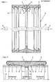
- FIG. 2 denote the smooth cylindrical ends of two pipes to be connected in a sealed manner, with the same outside and inside diameters.
- These pipes 1, 2 can be steel or cast iron sewage pipes.
- the device 3 which has a sealing collar 4 made of elastomeric material and a clamp band 5, which serves to clamp the sealing collar 4, is used for the sealed connection of these two pipes 1, 2.
- the clamp band 5 which is preferably made of thin-walled stainless steel sheet, is provided with two radially outwardly projecting bevels which can be pulled against one another in a known manner by means of screws in order to reduce the inside diameter of the clamp band. These parts of the clamp band 5 are not shown since they are known.
- the sealing collar 4 encompassed by the clamp band 5 has two annular sealing lips 6, 7 on its inner two outer edge regions and a centrally arranged, radially inwardly projecting, annular web 8, which serves as a stop for the two pipe ends 9, 10 to be inserted .
- a radially outwardly tapered inner wall section 11 extends between each side of the web 8 and each innermost sealing lip 7.
- the angle of inclination cK of these inner wall sections 11 with respect to the elongated longitudinal axis 12 of the device 3 is 15 ° ⁇ 1 ° in the exemplary embodiment.
- the sealing lips 6, 7 are bent inwards and the inclined inner wall sections 11 serve as guides for the tube ends until the tube ends 9, 10 on the annular web Strike 8.
- the sealing sleeve 4 is dimensioned taking into account the fluctuating outer diameter of the tubes 1, 2 so that the tube ends 9, 10 either come to lie directly in the corners 14 (FIG. 1) or somewhat radially inward from these corners 14. It is understood that the sealing sleeve 4 is in the relaxed state in this assembly phase.
- the clamp band 5 is contracted in the circumferential direction by means of the screws, not shown, and the sealing sleeve 4 is thereby preloaded radially inwards.
Landscapes
- Engineering & Computer Science (AREA)
- General Engineering & Computer Science (AREA)
- Mechanical Engineering (AREA)
- Physics & Mathematics (AREA)
- Fluid Mechanics (AREA)
- Joints With Sleeves (AREA)
- Flanged Joints, Insulating Joints, And Other Joints (AREA)
- Quick-Acting Or Multi-Walled Pipe Joints (AREA)
- Branch Pipes, Bends, And The Like (AREA)
- Non-Disconnectible Joints And Screw-Threaded Joints (AREA)
Priority Applications (1)
| Application Number | Priority Date | Filing Date | Title |
|---|---|---|---|
| AT85113106T ATE51695T1 (de) | 1984-11-03 | 1985-10-16 | Vorrichtung zur abgedichteten verbindung von zwei rohren mit glattzylindrischen enden. |
Applications Claiming Priority (2)
| Application Number | Priority Date | Filing Date | Title |
|---|---|---|---|
| DE3440258A DE3440258C2 (de) | 1984-11-03 | 1984-11-03 | Vorrichtung zur abgedichteten Verbindung von zwei Rohren mit glattzylindrischen Enden |
| DE3440258 | 1984-11-03 |
Publications (4)
| Publication Number | Publication Date |
|---|---|
| EP0180824A2 true EP0180824A2 (fr) | 1986-05-14 |
| EP0180824A3 EP0180824A3 (en) | 1987-09-09 |
| EP0180824B1 EP0180824B1 (fr) | 1990-04-04 |
| EP0180824B2 EP0180824B2 (fr) | 1994-02-23 |
Family
ID=6249458
Family Applications (1)
| Application Number | Title | Priority Date | Filing Date |
|---|---|---|---|
| EP85113106A Expired - Lifetime EP0180824B2 (fr) | 1984-11-03 | 1985-10-16 | Dispositif pour le raccordement étanche de deux conduits avec embouts lisses cylindriques |
Country Status (3)
| Country | Link |
|---|---|
| EP (1) | EP0180824B2 (fr) |
| AT (1) | ATE51695T1 (fr) |
| DE (2) | DE3440258C2 (fr) |
Cited By (7)
| Publication number | Priority date | Publication date | Assignee | Title |
|---|---|---|---|---|
| DE4103702C1 (fr) * | 1991-02-07 | 1992-06-04 | Mero Werke Kg | |
| US5351997A (en) * | 1990-07-27 | 1994-10-04 | Taylor Kerr (Couplings) Ltd. | Pipe coupling |
| GB2249366B (en) * | 1990-07-27 | 1994-12-14 | Taylor Kerr | Pipe coupling |
| EP0656502A3 (fr) * | 1993-12-02 | 1996-01-10 | Peter Ilesic | Dispositif d'étanchéité pour l'étanchement d'une tuyauterie. |
| US5639102A (en) * | 1993-12-02 | 1997-06-17 | Ile+E,Hac S+Ee I+E,Hac C+Ee ; Peter | Seal arrangement for sealing a conduit |
| US6457748B1 (en) | 1996-05-31 | 2002-10-01 | Taylor Kerr (Couplings) Ltd. | Fire-resistant pipe coupling |
| KR100562754B1 (ko) * | 2005-11-29 | 2006-03-21 | 백충원 | 합성수지관체 연결구 |
Families Citing this family (3)
| Publication number | Priority date | Publication date | Assignee | Title |
|---|---|---|---|---|
| DE3710852C1 (de) * | 1987-04-01 | 1988-03-10 | Rasmussen Gmbh | Rohrkupplung |
| AT390132B (de) * | 1988-03-10 | 1990-03-26 | Eternit Werke Hatschek L | Rohrkupplung |
| DE3817714A1 (de) * | 1988-05-25 | 1989-12-07 | Dueker Eisenwerk | Vorrichtung zur abgedichteten verbindung von zwei gussrohren |
Family Cites Families (7)
| Publication number | Priority date | Publication date | Assignee | Title |
|---|---|---|---|---|
| DE7316306U (de) * | 1973-08-02 | Eternit Ag | Spannschelle zur Verbindung muffenloser Leitungsrohre | |
| GB880847A (en) * | 1959-08-10 | 1961-10-25 | Stoneware Ltd | Coupling for pipes |
| CH432956A (de) * | 1965-11-10 | 1967-03-31 | Eternit Ag | Steck-Kupplung für Rohre |
| CH600228A5 (fr) * | 1976-10-13 | 1978-06-15 | Hobas Eng Ag | |
| DE8107112U1 (de) * | 1981-03-12 | 1982-01-14 | WOCO Franz-Josef Wolf & Co, 6483 Bad Soden-Salmünster | Steckmuffe |
| DE3122708C2 (de) * | 1981-06-06 | 1983-04-21 | Rasmussen Gmbh, 6457 Maintal | Gummimuffe für eine Breitbandschelle |
| DE3404739C1 (de) * | 1984-02-10 | 1985-07-25 | Rasmussen Gmbh, 6457 Maintal | Steckkupplung zum Verbinden der Enden zweier Rohre |
-
1984
- 1984-11-03 DE DE3440258A patent/DE3440258C2/de not_active Expired
-
1985
- 1985-10-16 AT AT85113106T patent/ATE51695T1/de active
- 1985-10-16 EP EP85113106A patent/EP0180824B2/fr not_active Expired - Lifetime
- 1985-10-16 DE DE8585113106T patent/DE3576992D1/de not_active Expired - Fee Related
Cited By (8)
| Publication number | Priority date | Publication date | Assignee | Title |
|---|---|---|---|---|
| US5351997A (en) * | 1990-07-27 | 1994-10-04 | Taylor Kerr (Couplings) Ltd. | Pipe coupling |
| GB2249366B (en) * | 1990-07-27 | 1994-12-14 | Taylor Kerr | Pipe coupling |
| DE4103702C1 (fr) * | 1991-02-07 | 1992-06-04 | Mero Werke Kg | |
| EP0656502A3 (fr) * | 1993-12-02 | 1996-01-10 | Peter Ilesic | Dispositif d'étanchéité pour l'étanchement d'une tuyauterie. |
| US5639102A (en) * | 1993-12-02 | 1997-06-17 | Ile+E,Hac S+Ee I+E,Hac C+Ee ; Peter | Seal arrangement for sealing a conduit |
| AU681449B2 (en) * | 1993-12-02 | 1997-08-28 | Peter Ilesic | Sealing arrangement for sealing conduits |
| US6457748B1 (en) | 1996-05-31 | 2002-10-01 | Taylor Kerr (Couplings) Ltd. | Fire-resistant pipe coupling |
| KR100562754B1 (ko) * | 2005-11-29 | 2006-03-21 | 백충원 | 합성수지관체 연결구 |
Also Published As
| Publication number | Publication date |
|---|---|
| DE3576992D1 (de) | 1990-05-10 |
| EP0180824A3 (en) | 1987-09-09 |
| DE3440258A1 (de) | 1986-05-22 |
| EP0180824B2 (fr) | 1994-02-23 |
| DE3440258C2 (de) | 1987-04-30 |
| ATE51695T1 (de) | 1990-04-15 |
| EP0180824B1 (fr) | 1990-04-04 |
Similar Documents
| Publication | Publication Date | Title |
|---|---|---|
| DE60214479T2 (de) | Wiederverwendbare Kupplung zum Verbinden von verstärkten Schlauchenden | |
| EP0477704B1 (fr) | Raccord comprimé pour tuyaux | |
| DE3330443A1 (de) | Rohrkupplung | |
| EP0111271B1 (fr) | Tuyau en plastique, particulièrement pour eaux usées | |
| DE2938791A1 (de) | Leitungsverbindung | |
| DE2621044A1 (de) | Rohrverbindung | |
| EP0180824B1 (fr) | Dispositif pour le raccordement étanche de deux conduits avec embouts lisses cylindriques | |
| EP0521822A1 (fr) | Dispositif pour le raccordement de deux gaines | |
| EP0557594B1 (fr) | Méthode de montage d'un élément de connexion | |
| EP0616162A1 (fr) | Anneau de bride pouvant être monté sur un tuyau en tôle à paroi mince et son procédé de fabrication | |
| CH461199A (de) | Rohrkupplung | |
| DE2922403A1 (de) | Rohrverbindungsstueck | |
| CH622597A5 (en) | Socket connection for pipes or pipe fittings | |
| DE2402892C2 (de) | Dichtungssystem für die stirnseitige Verbindung eines Rohres mit einem schraubenförmig gewellten Rohr | |
| DE2610878A1 (de) | Rohrverbindung mit einer schraubmuffe | |
| DE3014158C2 (fr) | ||
| EP1306601B1 (fr) | Raccords à compression pour la connection d'au moins un tuyau | |
| DE8701562U1 (de) | Dichtungseinrichtung | |
| DE4103702C1 (fr) | ||
| DE3911258C2 (fr) | ||
| CH653418A5 (en) | Clamping connection for smooth round bodies, in particular pipes or rods | |
| DE2815249A1 (de) | Verfahren und vorrichtung zum abdichten einer rohrverbindung | |
| EP0498322A1 (fr) | Dispositif d'étanchéité pour l'assemblage de deux extrémités à tuyaux cylindriques et lisses | |
| DE3403805A1 (de) | Verbindungsvorrichtung fuer koaxialkabel | |
| DE3203054A1 (de) | Doppelmuffe zur verbindung zweier rohre mit glattzylindrischen enden |
Legal Events
| Date | Code | Title | Description |
|---|---|---|---|
| PUAI | Public reference made under article 153(3) epc to a published international application that has entered the european phase |
Free format text: ORIGINAL CODE: 0009012 |
|
| AK | Designated contracting states |
Kind code of ref document: A2 Designated state(s): AT BE CH DE FR GB IT LI NL SE |
|
| PUAL | Search report despatched |
Free format text: ORIGINAL CODE: 0009013 |
|
| AK | Designated contracting states |
Kind code of ref document: A3 Designated state(s): AT BE CH DE FR GB IT LI NL SE |
|
| 17P | Request for examination filed |
Effective date: 19871028 |
|
| 17Q | First examination report despatched |
Effective date: 19880928 |
|
| GRAA | (expected) grant |
Free format text: ORIGINAL CODE: 0009210 |
|
| AK | Designated contracting states |
Kind code of ref document: B1 Designated state(s): AT BE CH DE FR GB IT LI NL SE |
|
| REF | Corresponds to: |
Ref document number: 51695 Country of ref document: AT Date of ref document: 19900415 Kind code of ref document: T |
|
| REF | Corresponds to: |
Ref document number: 3576992 Country of ref document: DE Date of ref document: 19900510 |
|
| GBT | Gb: translation of ep patent filed (gb section 77(6)(a)/1977) | ||
| ET | Fr: translation filed | ||
| ITF | It: translation for a ep patent filed | ||
| PLBI | Opposition filed |
Free format text: ORIGINAL CODE: 0009260 |
|
| 26 | Opposition filed |
Opponent name: RASMUSSEN GMBH Effective date: 19901221 |
|
| NLR1 | Nl: opposition has been filed with the epo |
Opponent name: RASMUSSEN GMBH |
|
| PG25 | Lapsed in a contracting state [announced via postgrant information from national office to epo] |
Ref country code: DE Effective date: 19910702 |
|
| ITTA | It: last paid annual fee | ||
| PUAH | Patent maintained in amended form |
Free format text: ORIGINAL CODE: 0009272 |
|
| STAA | Information on the status of an ep patent application or granted ep patent |
Free format text: STATUS: PATENT MAINTAINED AS AMENDED |
|
| RAP2 | Party data changed (patent owner data changed or rights of a patent transferred) |
Owner name: MERO-WERKE DR.-ING. MAX MENGERINGHAUSEN GMBH & CO. |
|
| 27A | Patent maintained in amended form |
Effective date: 19940223 |
|
| AK | Designated contracting states |
Kind code of ref document: B2 Designated state(s): AT BE CH DE FR GB IT LI NL SE |
|
| REG | Reference to a national code |
Ref country code: CH Ref legal event code: AEN |
|
| NLT2 | Nl: modifications (of names), taken from the european patent patent bulletin |
Owner name: MERO-WERKE DR.-ING. MAX MENGERINGHAUSEN GMBH & CO. |
|
| NLR2 | Nl: decision of opposition | ||
| ITF | It: translation for a ep patent filed | ||
| NLR3 | Nl: receipt of modified translations in the netherlands language after an opposition procedure | ||
| GBTA | Gb: translation of amended ep patent filed (gb section 77(6)(b)/1977) |
Effective date: 19940511 |
|
| ET3 | Fr: translation filed ** decision concerning opposition | ||
| PGFP | Annual fee paid to national office [announced via postgrant information from national office to epo] |
Ref country code: AT Payment date: 19941006 Year of fee payment: 10 |
|
| PGFP | Annual fee paid to national office [announced via postgrant information from national office to epo] |
Ref country code: GB Payment date: 19941011 Year of fee payment: 10 |
|
| EAL | Se: european patent in force in sweden |
Ref document number: 85113106.0 |
|
| PGFP | Annual fee paid to national office [announced via postgrant information from national office to epo] |
Ref country code: BE Payment date: 19950807 Year of fee payment: 11 |
|
| PGFP | Annual fee paid to national office [announced via postgrant information from national office to epo] |
Ref country code: CH Payment date: 19950922 Year of fee payment: 11 |
|
| PGFP | Annual fee paid to national office [announced via postgrant information from national office to epo] |
Ref country code: FR Payment date: 19950928 Year of fee payment: 11 |
|
| PG25 | Lapsed in a contracting state [announced via postgrant information from national office to epo] |
Ref country code: GB Effective date: 19951016 Ref country code: AT Effective date: 19951016 |
|
| PGFP | Annual fee paid to national office [announced via postgrant information from national office to epo] |
Ref country code: SE Payment date: 19951017 Year of fee payment: 11 |
|
| PGFP | Annual fee paid to national office [announced via postgrant information from national office to epo] |
Ref country code: NL Payment date: 19951027 Year of fee payment: 11 |
|
| GBPC | Gb: european patent ceased through non-payment of renewal fee |
Effective date: 19951016 |
|
| PG25 | Lapsed in a contracting state [announced via postgrant information from national office to epo] |
Ref country code: SE Effective date: 19961017 |
|
| PG25 | Lapsed in a contracting state [announced via postgrant information from national office to epo] |
Ref country code: LI Effective date: 19961031 Ref country code: CH Effective date: 19961031 Ref country code: BE Effective date: 19961031 |
|
| BERE | Be: lapsed |
Owner name: MERO-WERKE DR.-ING. MAX MENGERINGHAUSEN G.M.B.H. Effective date: 19961031 |
|
| PG25 | Lapsed in a contracting state [announced via postgrant information from national office to epo] |
Ref country code: NL Effective date: 19970501 |
|
| REG | Reference to a national code |
Ref country code: CH Ref legal event code: PL |
|
| PG25 | Lapsed in a contracting state [announced via postgrant information from national office to epo] |
Ref country code: FR Effective date: 19970630 |
|
| NLV4 | Nl: lapsed or anulled due to non-payment of the annual fee |
Effective date: 19970501 |
|
| EUG | Se: european patent has lapsed |
Ref document number: 85113106.0 |
|
| REG | Reference to a national code |
Ref country code: FR Ref legal event code: ST |
|
| APAH | Appeal reference modified |
Free format text: ORIGINAL CODE: EPIDOSCREFNO |