EP0180882A2 - Entnahmevorrichtung für Reifenvulkanisierformen - Google Patents
Entnahmevorrichtung für Reifenvulkanisierformen Download PDFInfo
- Publication number
- EP0180882A2 EP0180882A2 EP85113676A EP85113676A EP0180882A2 EP 0180882 A2 EP0180882 A2 EP 0180882A2 EP 85113676 A EP85113676 A EP 85113676A EP 85113676 A EP85113676 A EP 85113676A EP 0180882 A2 EP0180882 A2 EP 0180882A2
- Authority
- EP
- European Patent Office
- Prior art keywords
- ogive
- shaft
- extractor unit
- fact
- centering
- Prior art date
- Legal status (The legal status is an assumption and is not a legal conclusion. Google has not performed a legal analysis and makes no representation as to the accuracy of the status listed.)
- Granted
Links
Images


Classifications
-
- B—PERFORMING OPERATIONS; TRANSPORTING
- B29—WORKING OF PLASTICS; WORKING OF SUBSTANCES IN A PLASTIC STATE IN GENERAL
- B29D—PRODUCING PARTICULAR ARTICLES FROM PLASTICS OR FROM SUBSTANCES IN A PLASTIC STATE
- B29D30/00—Producing pneumatic or solid tyres or parts thereof
- B29D30/06—Pneumatic tyres or parts thereof (e.g. produced by casting, moulding, compression moulding, injection moulding, centrifugal casting)
- B29D30/0601—Vulcanising tyres; Vulcanising presses for tyres
- B29D30/0649—Devices for removing vulcanising cores, i.e. bladders, from the tyres; Opening the press in combination herewith
-
- B—PERFORMING OPERATIONS; TRANSPORTING
- B29—WORKING OF PLASTICS; WORKING OF SUBSTANCES IN A PLASTIC STATE IN GENERAL
- B29D—PRODUCING PARTICULAR ARTICLES FROM PLASTICS OR FROM SUBSTANCES IN A PLASTIC STATE
- B29D30/00—Producing pneumatic or solid tyres or parts thereof
- B29D30/06—Pneumatic tyres or parts thereof (e.g. produced by casting, moulding, compression moulding, injection moulding, centrifugal casting)
- B29D30/0601—Vulcanising tyres; Vulcanising presses for tyres
Definitions
- the present invention refers to a device for rapidly disassembling the part of the mould known as "centering extractor unit” from the driving mechanism of a press for vulcanizing pneumatic tyres, as well as to the improvements made to said extractor unit in order to permit the use of said device, through which the disassembling and reassembling operations can be carried out in a simple and rapid manner without using tools.
- the mould for vulcanizing a pneumatic tyre substantially comprises a fixed block that is apt to be connected to the frame of a vulcanizing press, and a mobile block connected to the driving mechanism of the press and movable with respect to said fixed block to allow the mould to be opened and closed; in the presses according to the invention, at the central part of the above said mobile block there is moreover a centering extractor unit which is able to originate the separation of the vulcanized pneumatic tyre from the mould blocks during the unloading step of the pneumatic tyre from the press.
- the above said extractor unit substantially comprises a body of annular shape, apt to be fixed to a mobile shaft of the press driving mechanism and a plurality of laminae radially movable in both directions with respect to said body to be led from a first configuration in which they are housed at the body inside to a second configuration in which they cooperate with the mould mobile block to obtain the blocking of the pneumatic tyre bead and vice versa.
- first connecting means substantially comprising two sets of radial teeth, those of a first set are obtained on the end of the first above said shaft, while the teeth of the second set are obtained on the annular body and are able to cooperate with the teeth of the other set to block the body with respect to the shaft in consequence of a relative rotation of the former with respect to the latter; moreover devices are arranged in order to prevent the extractor unit from casually becoming unscrewed from said shaft.
- Said devices are usually constituted by screws, able to prevent the annular body from rotating with respect to the shaft before the above said devices being removed from the seats where they are housed.
- the centering extractor unit comprises moreover a centering ogive which axially projects from the body itself and is connected to the above said shaft too; said centering ogive has the purpose of substantially maintaining in a correct position the curing bag, provided in the vulcanizing mould, during the insertion of the bag into the uncured carcass to be vulcanized, at the beginning of a new vulcanizing cycle, and during the inflation of the curing bag and the closing of the mould.
- the above said ogive is connected to the same shaft through second connecting means comprising two sets of radial teeth, those of a first set are obtained on the shaft and those of the second set are obtained on the ogive and are able to cooperate with the teeth of the other set to block the ogive with respect to the shaft in consequence of a relative rotation of the former with respect to the latter.
- second connecting means comprising two sets of radial teeth, those of a first set are obtained on the shaft and those of the second set are obtained on the ogive and are able to cooperate with the teeth of the other set to block the ogive with respect to the shaft in consequence of a relative rotation of the former with respect to the latter.
- suitable devices usually constituted by screws apt to allow the rotation of the ogive with respect to the shaft only when said devices have been removed from opportune seats where they are housed.
- said mobile block of the mould must be blocked with respect to the fixed one, through opportune toolings in order to avoid an accidental closing of the mould. Then the operator before unscrewing the ogive and the body of the extractor unit, has to remove the above mentioned devices which are arranged so as to avoid the accidental rotation of said parts; to this purpose it is necessary to act on the head of the above mentioned devices with suitable keys to remove them from their seats.
- the present invention aims at realizing a device for rapidly disassembling a centering extractor unit from the driving mechanism of a press for vulcanizing pneumatic tires, and an improved extractor unit to allow the use of said device through which the above mentioned drawbacks can be eliminated and in particular said disassembling operation can be carried out without waiting for the cooling of the mould and the press, without arranging opportune toolings that prevent the mould from accidentally closing and with simple and rapid operations.
- the present invention provides a centering extractor unit for pneumatic tyre vulcanizing moulds, suitable to be assembled on and operated by the driving mechanism of a press for vulcanizing pneumatic tyres, comprising a body having a substantially annular shape suitable to be fixed to a mobile shaft of said driving mechanism, and a plurality of laminae radially movable with respect to said body to be led from a first configuration in which they are housed at said body inside to a second configuration in which they radially project from said body, said connection between the extractor unit and said shaft being effected through first connecting means comprising a first set of radial teeth obtained on said shaft and a second set of radial teeth obtained on said body and able to cooperate with said teeth of the first set to block the body with respect to the shaft in consequence of a relative rotation between said elements, characterized by the fact that said body comprises first blocking means, alternatively and freely movable from a non-interference position to an interference position simultaneously with both said sets of teeth
- a second object of the present invention is a centering extractor unit for pneumatic tyre vulcanizing moulds, suitable to be assembled on and operated by the driving mechanism of a press for vulcanizing pneumatic tyres, comprising a centering ogive axially projecting from said body and connected to a mobile shaft of said driving mechanism through second connecting means comprising a first set of radial teeth obtained on said shaft and a second set of radial teeth obtained on said ogive and able to cooperate with said teeth of the first set to block the ogive with respect to the shaft in consequence of a rotation of the ogive with respect to the shaft, characterized by the fact of comprising second blocking means alternatively and freely movable from a non-interference position to an interference position simultaneously with said shaft and said ogive, disposed with said sets of teeth in position of mutual cooperation.
- a further object of the present invention is a device for assembling and disassembling a centering extractor unit for pneumatic tyre moulds, respectively on and from the driving mechanism of a press for vulcanizing pneumatic tyres, characterized by the fact of comprising a platten supported by the frame of said press in correspondence of the lower portion of said mould, coaxially with said press, a first disc axially and freely rotatable with respect to said platten, comprising means for associating with said annular body able to exercise a thrust on said first blocking means to lead them in said non-interference position, and means able to originate the rotation of said annular body around its own axis, a second disc axially and freely rotatable around said platten and said first disc comprising means for connecting with said centering ogive able to exercise a thrust on said second blocking means to lead them in said non-interference position, and means able to originate the rotation of said ogive around its own axis.
- said first blocking means comprise at least an oscillating lever which is suitable for being inserted into a corresponding cut obtained in the teeth of said first and second set of teeth to prevent said body from rotating with respect to said shaft, devices being provided for maintaining said lever, freely rotatable around the oscillating center, inside said cut.
- Said second blocking means comprise then a rod axially movable inside said ogive, a bar hinged to said rod and suitable for being inserted into a pair of slits obtained on said shaft and on said ogive to prevent said ogive from rotating with respect to said shaft, devices being provided to maintain said bar, freely rotatble around a hinged point with said rod, contemporaneously inside said slits.
- said thrusting means disposed on said device be essentially constituted by stakes suitable to be inserted into corresponding holes on said annular body and said ogive, in consequence of a relative movement of mutual approaching between said device and said centering extractor unit, and to exercise said thrust, both on said levers and on said bars, giving rise for both to their rotation around the corresponding hinged point and the consequent movement in the non-interference position with the driving shaft.
- the extractor unit and the device suitable for allowing to rapidly disassemble the driving mechanism of the press are schematically shown in figure 1, which illustrates entirely also the centripetal mould 2 for vulcanizing pneumatic tyres.
- Said mould substantially comprises a lower block 3 secured to a fixed platten 4, that makes part of the frame of a vulcanizing press, and a mobile upper block 5 secured to a mobile platten 6 that makes part of the driving mechanism of the press itself; the shown mould comprises moreover a plurality of sectors 7, each one can be radially moved with respect to the above said block under the drive of an opportune driving mechanism.
- the extractor unit 1 as clearly shown in figure 1, is substantially housed inside a central opening obtained in the block 5 and is connected to a shaft 8, axially movable with respect to the mould and driven by the press.
- the centering extractor unit comprises substantially an annular body 10 which is provided with a plurality of extracting laminae 11, radially movable with respect to said body, to be led from a first configuration in which they are housed substantially inside said body to a second configuration (not represented) in which they project from said body so as to impede the separation of the tyre bead from the extractor unit; each of said laminae is hinged to a pair of lever 12 oscillating on the body 10, able to substantially constitute with the relative lamina 11 an articulated quadrilateral; a projection 13 of one of the lever 12 cooperates with an annular groove 14 obtained inside a bush 15 integral with a tubular element 16 and a rod 17, axially movable inside the shaft 8.
- the relative axial movement between the shaft 8 and the tubular element 16 controls the radial movement of the above said laminae with respect to the supporting annular body.
- a first set of radial teeth 18 projects from the outer surface of the lower end of the shaft 8; each of said teeth is suitable for being housed in an annular cavity 19 obtained in the upper part of the body 10, as clearly shown in figure 2.
- Said body is then provided with a second set of radial teeth 20, each one is disposed over a corresponding tooth 18 so as to block it inside the cavity 19.
- Said two sets of teeth constitute the already cited first connecting means.
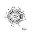
- a slot 21 (figure 3) is obtained in the body 10 between two contiguous teeth to allow the passage through it of a corresponding tooth 18 to be introduced inside the cavity 19.
- An oscillating lever 26 is hinged to a bracket 25 of the body 10 and is substantially disposed in a diametral plane of the body itself, the upper end 27 of the lever is inserted into a corresponding cut 28 obtained in a pair of teeth 18 and 20, so as to impede the relative rotation of the body 10 with respect to the shaft 8 when said teeth are in a position of mutual cooperation.
- said lever is kept inside the slit due to the action of a helical spring 29, which operates under tension while, a cam-shaped surface 30 is obtained in the lower part of the same to cooperate with corresponding parts of the device as it will be explained later on.
- Said lever 26 and the corresponding spring 29 constitute the preferred embodiment for said first blocking means and the sealing devices connected to these latter.
- the extractor unit comprises also an ogive 32 that axially projects downwardly with respect to the body 10 and that is arranged to cooperate with a curing bag (not shown) disposed on the lower part of the press, axially projecting from the lower block 3 of the mould, in order to maintain this bag substantially centered when the bag is inserted into the uncured carcass to be vulcanized, is inflated and when the mould is closed, at the beginning of each new vulcanizing cycle.
- a curing bag (not shown) disposed on the lower part of the press, axially projecting from the lower block 3 of the mould, in order to maintain this bag substantially centered when the bag is inserted into the uncured carcass to be vulcanized, is inflated and when the mould is closed, at the beginning of each new vulcanizing cycle.
- Said ogive is secured to the bush 15 with the same connection as that realized for connecting the body 10 to the shaft 8 and comprising a first set of radial teeth 33 projecting from said bush and suitable for being inserted into a substantially annular cavity obtained in the ogive 32; a second set of teeth 34 obtained in the upper part of the ogive 32 are superimposed to the teeth 33 to block them inside the above said cavity.
- a pair of radial slits 35 are obtained both in the bush 15 body, and in the ogive 32 body, are aligned with one another when the teeth of the bush and those of the ogive are in a position of mutual cooperation and are able to allow the insertion inside them of a bar 36 hinged to a rod 37, axially movable inside the ogive 32 and usually maintained in a first configuration, due to the action of a spring 38 which operates under compression; in the above mentioned configuration, shown in figure 2, said rod is in its downwardly stop position and the bar 36 is substantially orthogonal to said rod and is inserted inside the pair of slits 35 so as to prevent the ogive 32 from substantially rotating with respect to the bush 15; the rod 37 is led into a hole 37a of the ogive itself.
- the rod 37 with the bar 36 and the corresponding spring 38 constitute an embodiment preferred by the Applicant for said second blocking means and devices connected to these latter.
- the disassembling device according to the invention (figure 4) comprises a dragging unit and a support 40 which is disposed over a second shaft 41 that makes part of the vulcanizing press and that passes across a central opening of the lower block 3 of the mould; also said shaft, as the shaft 8, can be axially movable with respect to the press frame.
- the disassembling device 40 comprises a supporting platten 42 suitable to be placed on the shaft 41 in a position coaxial with said shaft, and a pair of rotatable discs 43 and 44 which are supported by a pair of rolling bearings 45.
- the disc 43 is integral with a shaft 46 rotatable on the platten 42 and provided with a head 47, having a central cavity 48, in which a cup-shaped element 49 provided with a stake 49a is axially movable; this cup-shaped element is torsionally integral with the head 47 and usually is maintained in its lifted position, shown in figure 4, due to the action of helical springs 50 which operate under compression.
- the disc 44 is provided with a plurality of stakes 51 disposed on its periphery in such a position as to be able to enter into corresponding holes 52 obtained on the body 10, in consequence of the mutual approaching of the extractor unit to the disassembling device 40. It is better to specify that in the preferred embodiment the stakes 51 are inserted into the corresponding holes 52 while the laminae 11 are radially projecting from the unit 10, i.e. in such a position as to leave the corresponding holes 52 open, i.e. accessible to the stake 51.
- the discs 43 and 44 are then provided with holes 53 suitable to receive the end of an opportune operating lever to drive their rotation with respect to the supporting platten 42; the disc 44 is moreover provided with a pair of flanges 54 able to cooperate with an opportune tooling destined to lift the disassembling device 40 for its drawing-away from the press and positioning, with and without the extractor unit.
- the dragging device 40 is firstly disposed on the lower part of the press and in particular on the shaft 41 as shown in the figure 4, after having removed the curing bag.
- the shaft 16 is set in action so as to radially extend the laminae 11, then the shaft 41 is driven to move upwardly for lifting said disassembling device (or in alternative the shaft 8 that supports the centering unit is lowered) up to lead the shafts 51 inside the holes 52 of the body 10 and consequently at least one of them into contact with the cam-shaped part 30 of the corresponding flange 26; said movement originates thus a kinematic connection between the cam-shaped profile of the flange and the above stake 51, and consequently the rotation of said flange, against the resistance of the spring 29, around its hinged point, with the result of releasing said flange from the corresponding cut 28.
- the cup-shaped element is advanced into contact with the ogive 32 so as to connect its radially inner surface with the radially outer one of the ogive and to insert the stake 49a into the hole 37a of the ogive itself; said motion drives the upwardly movement of the rod 37, overcoming the elastic reaction of the spring 38. Further to said upwardly movement of the rod 37, the bar 36 rotates and reaches a second configuration, shown with a broken line in figure 2, where its end substantially comes out of the slits 35, where it was housed, eliminating thus the blocking to the relative rotation between ogive and shaft.
- the rotation of the ogive with respect to the bush 15 is caused by the friction between the radially outer surface of the ogive and the radially inner one of the cup-shaped element or, in alternative, taking advantage of the characteristic of the stake 49a integral with the rotation with said cup.
- the body 10 rotates due to the action of the stakes 51, so as to release the radial teeth 20 of the body 10 from the corresponding teeth 18 of the shaft 8, to set said body free from the shafts in such a manner also the extractor unit is released from the shaft 8 and remains supported by the dragging device 40 and is released from the press by lowering the shaft 41 or, alternatively, by lifting the shaft 8.
Landscapes
- Engineering & Computer Science (AREA)
- Mechanical Engineering (AREA)
- Heating, Cooling, Or Curing Plastics Or The Like In General (AREA)
- Moulds For Moulding Plastics Or The Like (AREA)
Applications Claiming Priority (2)
| Application Number | Priority Date | Filing Date | Title |
|---|---|---|---|
| IT2348184 | 1984-11-07 | ||
| IT23481/84A IT1178624B (it) | 1984-11-07 | 1984-11-07 | Gruppo centratore estrattore modificato per stampi di vulcanizzazione pneumatici e dispositivo per il suo rapido smontaggio e rimontaggio da una pressa di vulcanizzazione |
Publications (3)
| Publication Number | Publication Date |
|---|---|
| EP0180882A2 true EP0180882A2 (de) | 1986-05-14 |
| EP0180882A3 EP0180882A3 (en) | 1988-07-27 |
| EP0180882B1 EP0180882B1 (de) | 1991-04-03 |
Family
ID=11207477
Family Applications (1)
| Application Number | Title | Priority Date | Filing Date |
|---|---|---|---|
| EP85113676A Expired EP0180882B1 (de) | 1984-11-07 | 1985-10-28 | Entnahmevorrichtung für Reifenvulkanisierformen |
Country Status (7)
| Country | Link |
|---|---|
| US (1) | US4604043A (de) |
| EP (1) | EP0180882B1 (de) |
| JP (1) | JPS61160210A (de) |
| BR (1) | BR8505725A (de) |
| DE (1) | DE3582396D1 (de) |
| ES (1) | ES8609023A1 (de) |
| IT (1) | IT1178624B (de) |
Families Citing this family (8)
| Publication number | Priority date | Publication date | Assignee | Title |
|---|---|---|---|---|
| IT1207848B (it) * | 1987-04-30 | 1989-06-01 | Cima Impianti Spa | Mobili radialmente e porzione macchina per la vulcanizzazione di superiore mobile assialmente edcopertoni con conchiglia a settori angolarmente. |
| JP3450027B2 (ja) * | 1993-05-07 | 2003-09-22 | 株式会社神戸製鋼所 | タイヤ加硫機における型交換台車 |
| EP0985506A1 (de) * | 1998-08-14 | 2000-03-15 | Detroy Holdings Limited | Formwerkzeug für Kunststoffprodukte |
| KR101462702B1 (ko) * | 2007-06-13 | 2014-11-17 | 프라티니 에스.피.에이. 코스트루찌오니 메카니체 | 금속 용기를 그리핑하고 핸들링하기 위한 장치 |
| JP2009097487A (ja) * | 2007-10-19 | 2009-05-07 | Honda Motor Co Ltd | 頭上カム軸型内燃機関の動弁装置 |
| JP2011085022A (ja) | 2009-10-13 | 2011-04-28 | Otics Corp | 車両用エンジン |
| CN111231388B (zh) * | 2020-02-11 | 2021-09-17 | 厦门科炬源自动化设备有限公司 | 一种免胶囊的轮胎硫化机 |
| CN119329102B (zh) * | 2024-12-19 | 2025-04-15 | 山东豪迈机械科技股份有限公司 | 一种轮胎硫化内腔模具快速拆装结构 |
Family Cites Families (13)
| Publication number | Priority date | Publication date | Assignee | Title |
|---|---|---|---|---|
| US3097394A (en) * | 1963-07-16 | Tire curing press | ||
| CH335217A (de) * | 1955-06-24 | 1958-12-31 | Starrfraesmaschinen Ag | Spannfutter mit lösbar befestigtem Werkzeugaufnahmestück an einer Arbeitsspindel |
| GB791841A (en) * | 1956-01-30 | 1958-03-12 | Us Rubber Co | Improvements in apparatus for shaping pneumatic tyres |
| GB866986A (en) * | 1957-11-18 | 1961-05-03 | Adolf Herbert | Improvements in or relating to vulcanising presses for vulcanising rubber tyres |
| US3002228A (en) * | 1958-06-06 | 1961-10-03 | Gen Tire & Rubber Co | Method of vulcanizing nylon tires |
| US3530533A (en) * | 1965-04-01 | 1970-09-29 | Nrm Corp | Loader for tire curing press |
| US3336636A (en) * | 1965-10-23 | 1967-08-22 | Mcneil Corp | Mounting mold sections used in vulcanizing presses |
| BE691025A (de) * | 1966-01-13 | 1967-05-16 | ||
| DE1579292A1 (de) * | 1966-02-21 | 1970-07-30 | Nii Shinnoi Promy | Vorrichtung zum Ausformen und Vulkanisieren von Luftreifenmaenteln |
| US3584335A (en) * | 1967-01-19 | 1971-06-15 | Nrm Corp | Tire curing press with loader and removal devices |
| US3487507A (en) * | 1967-11-29 | 1970-01-06 | Nrm Corp | Actuating device and control for tire curing press |
| IT1064031B (it) * | 1976-11-15 | 1985-02-18 | Pirelli | Dispositivo per il centraggio reciproco di elementi meccanici relativamente spostabili,particolarmente per l'impiego su presse di vulcanizzazione per pneumatici |
| IT1134120B (it) * | 1980-10-31 | 1986-07-24 | Pirelli | Miglioramenti nelle presse per la vulcanizzazione di pneumatici |
-
1984
- 1984-11-07 IT IT23481/84A patent/IT1178624B/it active
-
1985
- 1985-10-15 US US06/787,042 patent/US4604043A/en not_active Expired - Fee Related
- 1985-10-28 DE DE8585113676T patent/DE3582396D1/de not_active Expired - Lifetime
- 1985-10-28 EP EP85113676A patent/EP0180882B1/de not_active Expired
- 1985-11-07 ES ES549171A patent/ES8609023A1/es not_active Expired
- 1985-11-07 JP JP60249901A patent/JPS61160210A/ja active Pending
- 1985-11-07 BR BR8505725A patent/BR8505725A/pt unknown
Also Published As
| Publication number | Publication date |
|---|---|
| US4604043A (en) | 1986-08-05 |
| JPS61160210A (ja) | 1986-07-19 |
| BR8505725A (pt) | 1986-05-06 |
| EP0180882A3 (en) | 1988-07-27 |
| ES8609023A1 (es) | 1986-09-01 |
| DE3582396D1 (de) | 1991-05-08 |
| IT1178624B (it) | 1987-09-09 |
| EP0180882B1 (de) | 1991-04-03 |
| IT8423481A0 (it) | 1984-11-07 |
| ES549171A0 (es) | 1986-09-01 |
| IT8423481A1 (it) | 1986-05-07 |
Similar Documents
| Publication | Publication Date | Title |
|---|---|---|
| US4043725A (en) | Apparatus for molding pneumatic vehicular tires | |
| US4092090A (en) | Tire curing system | |
| US2730763A (en) | Tire curing press | |
| US4768937A (en) | Tire curing press | |
| US3065499A (en) | Tire carcass holder and curing press | |
| US2978741A (en) | Mechanism for holding and inflating tires after vulcanization | |
| US3065503A (en) | Tire curing press carcass loader | |
| JPH0572243B2 (de) | ||
| US4604043A (en) | Extractor unit for tire vulcanizing moulds and device for rapidly disassembling it from a vulcanizing press | |
| US2997740A (en) | Press for shaping and curing pneumatic tires | |
| JP2987232B2 (ja) | 自動車タイヤ用の加硫プレス | |
| JPS63212513A (ja) | 加硫金型 | |
| GB1399703A (en) | Press for shaping and curing tyres and a method of and means for loading an uncured tyre band into such a press | |
| JP2009149075A (ja) | タイヤ硬化金型の組立/分解装置およびその方法 | |
| JP2009149081A (ja) | タイヤ製作・硬化ステーション結合装置およびその方法 | |
| US2808618A (en) | Press for shaping and vulcanizing pneumatic tires | |
| US3229329A (en) | Tire curing press and loader therefor | |
| AU687037B2 (en) | Apparatus and method for retreading a tire | |
| US3674899A (en) | Process for curing pneumatic tires | |
| CN115922989B (zh) | 一种轮胎硫化装置 | |
| US4726861A (en) | Method and device for automatically centering and feeding beads onto a tire building drum | |
| US2903742A (en) | Apparatus for retreading tires | |
| JPH06285862A (ja) | タイヤ加硫プレス用ブラダ組立体の取付装置及び搬送装置 | |
| US3336636A (en) | Mounting mold sections used in vulcanizing presses | |
| KR0149977B1 (ko) | 블래더리스타이어가류기에의 생타이어장착방법 및 그 장치 |
Legal Events
| Date | Code | Title | Description |
|---|---|---|---|
| PUAI | Public reference made under article 153(3) epc to a published international application that has entered the european phase |
Free format text: ORIGINAL CODE: 0009012 |
|
| AK | Designated contracting states |
Kind code of ref document: A2 Designated state(s): DE FR GB |
|
| RHK1 | Main classification (correction) |
Ipc: B29D 30/06 |
|
| PUAL | Search report despatched |
Free format text: ORIGINAL CODE: 0009013 |
|
| AK | Designated contracting states |
Kind code of ref document: A3 Designated state(s): DE FR GB |
|
| 17P | Request for examination filed |
Effective date: 19890126 |
|
| 17Q | First examination report despatched |
Effective date: 19890712 |
|
| GRAA | (expected) grant |
Free format text: ORIGINAL CODE: 0009210 |
|
| AK | Designated contracting states |
Kind code of ref document: B1 Designated state(s): DE FR GB |
|
| REF | Corresponds to: |
Ref document number: 3582396 Country of ref document: DE Date of ref document: 19910508 |
|
| ET | Fr: translation filed | ||
| PGFP | Annual fee paid to national office [announced via postgrant information from national office to epo] |
Ref country code: FR Payment date: 19910924 Year of fee payment: 7 |
|
| PGFP | Annual fee paid to national office [announced via postgrant information from national office to epo] |
Ref country code: GB Payment date: 19910930 Year of fee payment: 7 |
|
| PGFP | Annual fee paid to national office [announced via postgrant information from national office to epo] |
Ref country code: DE Payment date: 19911231 Year of fee payment: 7 |
|
| PLBE | No opposition filed within time limit |
Free format text: ORIGINAL CODE: 0009261 |
|
| STAA | Information on the status of an ep patent application or granted ep patent |
Free format text: STATUS: NO OPPOSITION FILED WITHIN TIME LIMIT |
|
| 26N | No opposition filed | ||
| PG25 | Lapsed in a contracting state [announced via postgrant information from national office to epo] |
Ref country code: GB Effective date: 19921028 |
|
| GBPC | Gb: european patent ceased through non-payment of renewal fee |
Effective date: 19921028 |
|
| PG25 | Lapsed in a contracting state [announced via postgrant information from national office to epo] |
Ref country code: FR Effective date: 19930630 |
|
| PG25 | Lapsed in a contracting state [announced via postgrant information from national office to epo] |
Ref country code: DE Effective date: 19930701 |
|
| REG | Reference to a national code |
Ref country code: FR Ref legal event code: ST |