EP0180937A2 - Coffrage pour éléments de construction en béton armé fabriqués en série et en particulier pour traverses d'aiguillages en béton précontraint - Google Patents
Coffrage pour éléments de construction en béton armé fabriqués en série et en particulier pour traverses d'aiguillages en béton précontraint Download PDFInfo
- Publication number
- EP0180937A2 EP0180937A2 EP85113957A EP85113957A EP0180937A2 EP 0180937 A2 EP0180937 A2 EP 0180937A2 EP 85113957 A EP85113957 A EP 85113957A EP 85113957 A EP85113957 A EP 85113957A EP 0180937 A2 EP0180937 A2 EP 0180937A2
- Authority
- EP
- European Patent Office
- Prior art keywords
- base plate
- parts
- built
- formwork
- diameter
- Prior art date
- Legal status (The legal status is an assumption and is not a legal conclusion. Google has not performed a legal analysis and makes no representation as to the accuracy of the status listed.)
- Granted
Links
- 239000011150 reinforced concrete Substances 0.000 title claims description 3
- 238000009416 shuttering Methods 0.000 title 1
- 238000009415 formwork Methods 0.000 claims abstract description 31
- 210000000078 claw Anatomy 0.000 claims abstract description 11
- 239000011513 prestressed concrete Substances 0.000 claims abstract 2
- 238000009434 installation Methods 0.000 claims description 7
- 230000037431 insertion Effects 0.000 claims 1
- 238000003780 insertion Methods 0.000 claims 1
- 241000251131 Sphyrna Species 0.000 abstract description 2
- 239000004567 concrete Substances 0.000 description 4
- 239000004568 cement Substances 0.000 description 3
- 230000035515 penetration Effects 0.000 description 3
- 101100390736 Danio rerio fign gene Proteins 0.000 description 2
- 101100390738 Mus musculus Fign gene Proteins 0.000 description 2
- 238000010276 construction Methods 0.000 description 2
- 229910000831 Steel Inorganic materials 0.000 description 1
- 238000004873 anchoring Methods 0.000 description 1
- 238000009412 basement excavation Methods 0.000 description 1
- 238000005452 bending Methods 0.000 description 1
- 238000010586 diagram Methods 0.000 description 1
- 238000006073 displacement reaction Methods 0.000 description 1
- 230000000149 penetrating effect Effects 0.000 description 1
- 239000010959 steel Substances 0.000 description 1
- 239000000725 suspension Substances 0.000 description 1
Images


Classifications
-
- B—PERFORMING OPERATIONS; TRANSPORTING
- B28—WORKING CEMENT, CLAY, OR STONE
- B28B—SHAPING CLAY OR OTHER CERAMIC COMPOSITIONS; SHAPING SLAG; SHAPING MIXTURES CONTAINING CEMENTITIOUS MATERIAL, e.g. PLASTER
- B28B23/00—Arrangements specially adapted for the production of shaped articles with elements wholly or partly embedded in the moulding material; Production of reinforced objects
- B28B23/005—Arrangements specially adapted for the production of shaped articles with elements wholly or partly embedded in the moulding material; Production of reinforced objects with anchoring or fastening elements for the shaped articles
-
- B—PERFORMING OPERATIONS; TRANSPORTING
- B28—WORKING CEMENT, CLAY, OR STONE
- B28B—SHAPING CLAY OR OTHER CERAMIC COMPOSITIONS; SHAPING SLAG; SHAPING MIXTURES CONTAINING CEMENTITIOUS MATERIAL, e.g. PLASTER
- B28B23/00—Arrangements specially adapted for the production of shaped articles with elements wholly or partly embedded in the moulding material; Production of reinforced objects
- B28B23/02—Arrangements specially adapted for the production of shaped articles with elements wholly or partly embedded in the moulding material; Production of reinforced objects wherein the elements are reinforcing members
- B28B23/022—Means for inserting reinforcing members into the mould or for supporting them in the mould
- B28B23/024—Supporting means
- B28B23/026—Mould partitionning elements acting as supporting means in moulds, e.g. for elongated articles
Definitions
- the invention relates to a formwork for prefabricated parts made of reinforced concrete, as generically described in the preamble of claim 1.
- the fixing means for the built-in parts are inserted from above into recesses in the base plate, so as to fix them in terms of their geometrical position, while holding them from above by tensioning devices arranged on the side elements of the formwork be pressed firmly against the floor slab.
- the disadvantage of such fixation of the built-in parts is that the device parts projecting beyond the upper formwork edge make it impossible to pull off the formwork over the edges of the side elements and the use of vibrating planks to compact the concrete.
- the fixing means are inserted in front of the displacement of the bottom plate (die) and combined with the base plate or must be installed from the difficult-to ga n equalized bottom of the formwork forth.
- the arrangement of the suspension devices for lifting the sleepers and the conical ends of the fastening bolts show that even with this formwork solution there is no free top of the formwork for pulling off and compacting with a vibrating screed.
- the sleepers are manufactured with the sole surface upwards. After excavation, the finished part must be turned for equipment and storage. In order to be able to finally store them, both formwork solutions require a special setting, in which auxiliary devices protruding from the base surface must be removed.
- the object of the invention is to develop a formwork in which all auxiliary devices including the fixing means can be installed from above and also do not protrude beyond the upper formwork edge.
- Embodiments of the invention contain claims 2 to 4.
- the invention solves the problem by a system of rail-like profiles in the substructure of the fitted bed.
- each position required for formwork of the different precast elements can be fixed in the fitted bed.
- Retaining screws which are at least flush with the upper formwork edge and which hold the individually movable built-in components in the formwork immovably can be screwed into the screw sleeves from above. When concreting, it can be pulled off over the formwork edge and compacted with a vibrating screed.
- Claim 2 describes an expedient embodiment of a clamping screw 9 and additional elements, with the aid of which the built-in part 8 is protected against bending and cement against the penetration of cement paste into the interior of the built-in part 8.
- the clamping screw 9 has an Allen head so that it can be released without protruding from the concrete surface.
- a shoulder 48 is formed between the Allen head and the shaft, with which it presses an elastic ring 49 against a nut 40.
- the nut passes on the pressure via a washer 51 to the mounting part 8, the lower edge of which is pressed tightly against the base plate, thereby preventing cement paste from penetrating into the interior of the mounting part 8.
- the shaft of the tensioning screw 9 tapers in the central area and thereby creates space for a mounting sleeve 44 for centering the built-in part 8.
- the cover 50 according to claim 3 protects the Allen key as well as the interior of the built-in part 8 against the penetration of concrete during concreting.
- the measure according to claim 4 prevents that the bottom plate is distorted by tightening the clamping screws.
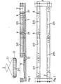
- a clamping bed 1 in which the tie rods 3 are clamped from abutment to abutment, finished parts 2/1, 2 ... n are produced one behind the other in a formwork which extends essentially in the longitudinal direction.
- the formwork is built up from the side elements 4 of the instep bed, the base plates 5/1, 2, ... n fitted between them and storage elements 6.
- the base plates 5 have recesses 7 - in the example shown simple bores - through which the position of built-in parts 8 of the prefabricated parts 2 in the formwork can be geometrically defined in the form of templates.
- the fastening of the built-in parts 8 - in the example shown tube sleeves - serve screws 9, which are anchored in the floor to be rigid and tensile for exact fixing.
- This rigid and tensile anchoring is achieved by the fastening screw 9 from above to for stop 10 is screwed into a threaded sleeve 11 arranged under the fitted base plate 5.
- the threaded sleeve 11 as well as the tubular sleeve 8 are pressed firmly and rigidly against the base plate 5 and the clamping claw 12 stiffening them by tightening the screw 9.
- the position of the threaded sleeves 11 can be adapted to any possible desired arrangement, which is predetermined by the recesses 7 of the base plate 5, in that the sleeves 11 are designed like hammer heads and can be displaced transversely in recesses 14 of the clamping claws 12 with this hammer head 13 and the clamping claws 12 with lugs 15 in corresponding, arranged in the formwork of the longitudinal rails 16 are longitudinally displaceable.
- the sleeves 12 can thus assume any position under the base plate 5.
- the upper edges of the threaded sleeves 11 of the clamping claws 12 and the longitudinal rail 16 are arranged exactly in one plane, so that the base plate 5 is not distorted when the clamping screw 9 is tightened.
- the built-in elements 6 are special built-in parts in the fitted bed.
- the set-off element 6 comprises the top formwork of two adjoining prefabricated parts 2 / n, 2 / n + 1 in the fitted bed 1. It is fastened with the aid of a clamping screw 30 which is inserted into a screw sleeve 34 Clamping device 27 can be screwed in.
- the clamping device 27 engages with its ends into the profiles of the longitudinal rails 16, is longitudinally displaceable in them and can be firmly clamped with the aid of the clamping block 29.
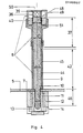
- the clamping screw 9 has a screw head 36 with an Allen key. Its shaft is divided into an upper shaft part 37 with the shaft diameter 38 and a lower shaft part 42 with a shaft diameter 43 that is smaller than the upper shaft part 37.
- the shaft diameter 38 is slightly smaller than the diameter of the screw head 36.
- the shoulder 48 is created by the jump in diameter.
- the clamping screw 9 ends in the threaded part 46, the external thread diameter 47 of which is smaller than the external diameter 43 of the lower shaft part 42. This creates the stop 10 between the shaft part 42 and the threaded part 46, against which the base plate 5 by screwing the clamping screw 9 against the threaded sleeve 11 is pressed firmly.
- the clamping screw 9 can be pushed through the nut 40 of the rail fastening which is permanently installed in the head part of the installation part 8.
- the upper shaft diameter 38 is therefore slightly smaller than the inner thread diameter 41 of the nut 40.
- the lower shaft part 42 of the clamping screw 9 stands in a mounting sleeve 44 for guiding the installation part 8.
- the shoulder 48 of the screw head 36 presses on an elastic ring 49 which The mounting part 8 presses firmly onto the base plate 5 via the nut 40 and the washer 51.
- a lid 50 ver closes the opening for inserting the clamping screw 9 in the head part 39 of the installation part 8 flush with the upper edge of the side elements 4 of the formwork and thus protects the installation part 8 against the penetration of concrete.
- All of the built-in parts 9, 17, 21, 30 which can be inserted into the fitted bed 1 are dimensioned in such a way that they do not protrude beyond the edge of the side elements 4.
Landscapes
- Engineering & Computer Science (AREA)
- Manufacturing & Machinery (AREA)
- Chemical & Material Sciences (AREA)
- Ceramic Engineering (AREA)
- Mechanical Engineering (AREA)
- Manufacturing Of Tubular Articles Or Embedded Moulded Articles (AREA)
- Moulds, Cores, Or Mandrels (AREA)
- Forms Removed On Construction Sites Or Auxiliary Members Thereof (AREA)
- Moulding By Coating Moulds (AREA)
Priority Applications (1)
| Application Number | Priority Date | Filing Date | Title |
|---|---|---|---|
| AT85113957T ATE50527T1 (de) | 1984-11-03 | 1985-11-02 | Schalung fuer serienfertigteile aus stahlbeton, vornehmlich fuer vorgespannte weichenschwellen. |
Applications Claiming Priority (2)
| Application Number | Priority Date | Filing Date | Title |
|---|---|---|---|
| DE3440247A DE3440247A1 (de) | 1984-11-03 | 1984-11-03 | Schalung fuer serienfertigteile aus stahlbeton, vornehmlich fuer vorgespannte weichenschwellen |
| DE3440247 | 1984-11-03 |
Publications (3)
| Publication Number | Publication Date |
|---|---|
| EP0180937A2 true EP0180937A2 (fr) | 1986-05-14 |
| EP0180937A3 EP0180937A3 (en) | 1988-07-27 |
| EP0180937B1 EP0180937B1 (fr) | 1990-02-28 |
Family
ID=6249451
Family Applications (2)
| Application Number | Title | Priority Date | Filing Date |
|---|---|---|---|
| EP85113957A Expired - Lifetime EP0180937B1 (fr) | 1984-11-03 | 1985-11-02 | Coffrage pour éléments de construction en béton armé fabriqués en série et en particulier pour traverses d'aiguillages en béton précontraint |
| EP85113956A Expired - Lifetime EP0183087B1 (fr) | 1984-11-03 | 1985-11-02 | Coffrage pour éléments de construction en béton armé fabriqués en série, et en particulier pour traverses d'aiguillages en béton précontraint |
Family Applications After (1)
| Application Number | Title | Priority Date | Filing Date |
|---|---|---|---|
| EP85113956A Expired - Lifetime EP0183087B1 (fr) | 1984-11-03 | 1985-11-02 | Coffrage pour éléments de construction en béton armé fabriqués en série, et en particulier pour traverses d'aiguillages en béton précontraint |
Country Status (3)
| Country | Link |
|---|---|
| EP (2) | EP0180937B1 (fr) |
| AT (2) | ATE51795T1 (fr) |
| DE (3) | DE3440247A1 (fr) |
Cited By (4)
| Publication number | Priority date | Publication date | Assignee | Title |
|---|---|---|---|---|
| WO1988002049A1 (fr) * | 1986-08-27 | 1988-03-24 | Wayss & Freytag Ag | Dispositif pour la fixation de pieces de montage en forme de tube |
| EP1033439A1 (fr) * | 1999-03-03 | 2000-09-06 | Thyssen Krupp Materials & Services AG | Bride de fixation d'un rail de chemin de fer avec une traverse ou un plateau |
| CN108748622A (zh) * | 2018-08-30 | 2018-11-06 | 湖南中铁五新钢模有限责任公司 | 一种pc轨道梁底模系统 |
| CN111231090A (zh) * | 2020-01-19 | 2020-06-05 | 惠州市鑫业建材有限公司 | 一种全自动高效的蒸压加气混凝土砌块脱模装置 |
Families Citing this family (4)
| Publication number | Priority date | Publication date | Assignee | Title |
|---|---|---|---|---|
| DE3815178C1 (en) * | 1988-05-04 | 1989-08-10 | Wayss & Freytag Ag, 6000 Frankfurt, De | Process for the repeated use of the metal base plate of a shuttering for series-produced prefabricated parts consisting of concrete with a different arrangement of installation parts |
| EP0350620B1 (fr) * | 1988-07-14 | 1992-04-29 | Wayss & Freytag Aktiengesellschaft | Méthode pour fabriquer des traverses pour aiguillages en béton |
| NL1004064C2 (nl) * | 1996-09-18 | 1998-03-19 | Leenstra Machine En Staalbouw | Inrichting voor het vervaardigen van heipalen. |
| DE102018108634A1 (de) | 2018-04-11 | 2019-10-17 | Rail.One Gmbh | Fertigungsanlage für Betonschwellen und zugehöriges Betriebsverfahren |
Family Cites Families (9)
| Publication number | Priority date | Publication date | Assignee | Title |
|---|---|---|---|---|
| NL62650C (fr) * | 1943-04-08 | |||
| GB709123A (en) * | 1951-06-22 | 1954-05-19 | Dowsett Engineering Constructi | Manufacture of concrete railway sleepers or similar beams |
| US3070867A (en) * | 1959-12-21 | 1963-01-01 | Theodore J Belle | Strand holder and dam for prestressed concrete molds |
| US3071836A (en) * | 1960-04-06 | 1963-01-08 | Fmc Corp | Double-t beam forming apparatus |
| FR1565510A (fr) * | 1968-02-21 | 1969-05-02 | ||
| FR2254946A5 (en) * | 1973-12-17 | 1975-07-11 | Costamagna & Cie B M | Production system for concrete railway sleepers - has portal frames with vertically movable reinforcement positioning beam |
| SE415868B (sv) * | 1978-12-05 | 1980-11-10 | A Betong Ab | Sett att tillverka betongsliperbolock samt matrisuppsettning for utforande av settet |
| FR2519898B1 (fr) * | 1982-01-21 | 1987-08-28 | Vagneux Traverses Beton Arme S | Ensemble de moulage d'elements en beton arme precontraint, notamment de traverses, et procede de fabrication de ces elements |
| IT1149739B (it) * | 1982-02-04 | 1986-12-10 | Ind Prefabbricati Affini Ipa S | Procedimento ed apparecchiatura per la realizzazione di manufatti prefabbricati in cemento armato precompresso muniti di inserti,in particolare per la fabbricazione di traverse ad uso ferroviario |
-
1984
- 1984-11-03 DE DE3440247A patent/DE3440247A1/de active Granted
-
1985
- 1985-11-02 AT AT85113956T patent/ATE51795T1/de active
- 1985-11-02 AT AT85113957T patent/ATE50527T1/de not_active IP Right Cessation
- 1985-11-02 EP EP85113957A patent/EP0180937B1/fr not_active Expired - Lifetime
- 1985-11-02 EP EP85113956A patent/EP0183087B1/fr not_active Expired - Lifetime
- 1985-11-02 DE DE8585113956T patent/DE3577057D1/de not_active Expired - Lifetime
- 1985-11-02 DE DE8585113957T patent/DE3576137D1/de not_active Expired - Lifetime
Cited By (9)
| Publication number | Priority date | Publication date | Assignee | Title |
|---|---|---|---|---|
| WO1988002049A1 (fr) * | 1986-08-27 | 1988-03-24 | Wayss & Freytag Ag | Dispositif pour la fixation de pieces de montage en forme de tube |
| DE3629030A1 (de) * | 1986-08-27 | 1988-04-14 | Wayss & Freytag Ag | Vorrichtung zur fixierung roehrenfoermiger einbauteile |
| EP0268028A1 (fr) * | 1986-08-27 | 1988-05-25 | Wayss & Freytag Aktiengesellschaft | Dispositif pour localiser des pièces tubulaires pour le montage |
| US4948089A (en) * | 1986-08-27 | 1990-08-14 | Wayss & Freytag Aktiengesellschaft | Concrete mold with arrangement for mounting tubular components |
| EP1033439A1 (fr) * | 1999-03-03 | 2000-09-06 | Thyssen Krupp Materials & Services AG | Bride de fixation d'un rail de chemin de fer avec une traverse ou un plateau |
| CN108748622A (zh) * | 2018-08-30 | 2018-11-06 | 湖南中铁五新钢模有限责任公司 | 一种pc轨道梁底模系统 |
| CN108748622B (zh) * | 2018-08-30 | 2024-05-03 | 湖南五新智能科技股份有限公司 | 一种pc轨道梁底模系统 |
| CN111231090A (zh) * | 2020-01-19 | 2020-06-05 | 惠州市鑫业建材有限公司 | 一种全自动高效的蒸压加气混凝土砌块脱模装置 |
| CN111231090B (zh) * | 2020-01-19 | 2021-06-04 | 惠州市鑫业建材有限公司 | 一种全自动高效的蒸压加气混凝土砌块脱模装置 |
Also Published As
| Publication number | Publication date |
|---|---|
| DE3577057D1 (de) | 1990-05-17 |
| EP0183087A2 (fr) | 1986-06-04 |
| DE3440247C2 (fr) | 1987-08-27 |
| ATE50527T1 (de) | 1990-03-15 |
| EP0180937A3 (en) | 1988-07-27 |
| DE3440247A1 (de) | 1986-05-22 |
| EP0180937B1 (fr) | 1990-02-28 |
| DE3576137D1 (de) | 1990-04-05 |
| EP0183087B1 (fr) | 1990-04-11 |
| EP0183087A3 (en) | 1988-07-20 |
| ATE51795T1 (de) | 1990-04-15 |
Similar Documents
| Publication | Publication Date | Title |
|---|---|---|
| DE2840195C3 (de) | Vorrichtung zum Befestigen von zur Aufnahme von Brennelement-Bündeln dienenden Lagerkästen am Boden eines Wasserbeckens | |
| DE3530694C2 (fr) | ||
| DE3539225A1 (de) | Verfahren zum einbau eines gleisrosts | |
| EP0180937A2 (fr) | Coffrage pour éléments de construction en béton armé fabriqués en série et en particulier pour traverses d'aiguillages en béton précontraint | |
| EP0410079A1 (fr) | Coffrage de raccordement pour panneaux en béton reliés | |
| DE3117547A1 (de) | Vorrichtung zur halterung von verkleidungsplatten u.dgl. an bauwerksteilen | |
| DE4406105A1 (de) | Befestigungsanordnung für eine Schiene | |
| DE10246898A1 (de) | Vorrichtung zum Justieren der Schwellen von festen Fahrbahnen | |
| DE3153198C2 (de) | Einbaulehre für mindestens zwei getrennte Ankerelemente | |
| DE2912131C2 (de) | Garage | |
| AT400465B (de) | Schalung und verfahren zum giessen eines behälters aus beton | |
| DE2921480C2 (fr) | ||
| DE4447600C2 (de) | Vorrichtung zum vorläufigen Fixieren von Gleisen | |
| DE3200262A1 (de) | Verankerungseinrichtung fuer ein traggeruest einer aussenwand oder einer tragenden zwischenwand eines aus vorgefertigten teilen bestehenden montierbaren gebaeudes | |
| DE19545341A1 (de) | Gleitstuhl | |
| DE2906207A1 (de) | Schwundfugenkonstruktion fuer industrieboeden, fussboeden, waende, decken und tunnels | |
| EP0808945A2 (fr) | Superstructure de voie ferrée | |
| DE202024103142U1 (de) | Vorrichtung zur Befestigung einer senkrecht ausgerichteten Geländerplatte durch Verkeilung zwischen den Innenwandungen des Führungskanals eines Bodenträgerprofils | |
| DE2408756C3 (de) | Bahnübergang | |
| DE1434673B2 (de) | Transformatorenstation aus uebereinandergestellten vorgefertigten betonplatten und eckteilen | |
| DE2309723C3 (de) | Verfahren und Vorrichtung zur Justierung von Fertigteilwänden und -stützen von Gebäuden | |
| DE2212118A1 (de) | Kletterschalung | |
| DE2313272A1 (de) | Montagevorrichtung zum befestigen von fertigbauteilen | |
| DE1987925U (de) | Halterung fuer im abstand von einer flaeche zu befestigende elemente, wie verkleidungsplatten, verblendsteine usw. | |
| DE3448053A1 (de) | Schalung fuer serienfertigteile aus stahlbeton, vornehmlich fuer vorgespannte weichenschwellen |
Legal Events
| Date | Code | Title | Description |
|---|---|---|---|
| PUAI | Public reference made under article 153(3) epc to a published international application that has entered the european phase |
Free format text: ORIGINAL CODE: 0009012 |
|
| AK | Designated contracting states |
Kind code of ref document: A2 Designated state(s): AT CH DE LI |
|
| PUAL | Search report despatched |
Free format text: ORIGINAL CODE: 0009013 |
|
| AK | Designated contracting states |
Kind code of ref document: A3 Designated state(s): AT CH DE LI |
|
| 17P | Request for examination filed |
Effective date: 19880711 |
|
| 17Q | First examination report despatched |
Effective date: 19890419 |
|
| GRAA | (expected) grant |
Free format text: ORIGINAL CODE: 0009210 |
|
| AK | Designated contracting states |
Kind code of ref document: B1 Designated state(s): AT CH DE LI |
|
| REF | Corresponds to: |
Ref document number: 50527 Country of ref document: AT Date of ref document: 19900315 Kind code of ref document: T |
|
| REF | Corresponds to: |
Ref document number: 3576137 Country of ref document: DE Date of ref document: 19900405 |
|
| PLBE | No opposition filed within time limit |
Free format text: ORIGINAL CODE: 0009261 |
|
| STAA | Information on the status of an ep patent application or granted ep patent |
Free format text: STATUS: NO OPPOSITION FILED WITHIN TIME LIMIT |
|
| 26N | No opposition filed | ||
| PGFP | Annual fee paid to national office [announced via postgrant information from national office to epo] |
Ref country code: CH Payment date: 19941010 Year of fee payment: 10 |
|
| PGFP | Annual fee paid to national office [announced via postgrant information from national office to epo] |
Ref country code: AT Payment date: 19941013 Year of fee payment: 10 |
|
| PG25 | Lapsed in a contracting state [announced via postgrant information from national office to epo] |
Ref country code: AT Effective date: 19951102 |
|
| PG25 | Lapsed in a contracting state [announced via postgrant information from national office to epo] |
Ref country code: LI Effective date: 19951130 Ref country code: CH Effective date: 19951130 |
|
| REG | Reference to a national code |
Ref country code: CH Ref legal event code: PL |
|
| PGFP | Annual fee paid to national office [announced via postgrant information from national office to epo] |
Ref country code: DE Payment date: 19961023 Year of fee payment: 12 |
|
| PG25 | Lapsed in a contracting state [announced via postgrant information from national office to epo] |
Ref country code: DE Free format text: LAPSE BECAUSE OF NON-PAYMENT OF DUE FEES Effective date: 19980801 |