EP0181034A1 - Dispositif de pesage - Google Patents
Dispositif de pesage Download PDFInfo
- Publication number
- EP0181034A1 EP0181034A1 EP85201770A EP85201770A EP0181034A1 EP 0181034 A1 EP0181034 A1 EP 0181034A1 EP 85201770 A EP85201770 A EP 85201770A EP 85201770 A EP85201770 A EP 85201770A EP 0181034 A1 EP0181034 A1 EP 0181034A1
- Authority
- EP
- European Patent Office
- Prior art keywords
- frames
- frame
- strips
- load
- strip
- Prior art date
- Legal status (The legal status is an assumption and is not a legal conclusion. Google has not performed a legal analysis and makes no representation as to the accuracy of the status listed.)
- Granted
Links
Images


Classifications
-
- G—PHYSICS
- G01—MEASURING; TESTING
- G01G—WEIGHING
- G01G19/00—Weighing apparatus or methods adapted for special purposes not provided for in the preceding groups
- G01G19/08—Weighing apparatus or methods adapted for special purposes not provided for in the preceding groups for incorporation in vehicles
-
- A—HUMAN NECESSITIES
- A01—AGRICULTURE; FORESTRY; ANIMAL HUSBANDRY; HUNTING; TRAPPING; FISHING
- A01B—SOIL WORKING IN AGRICULTURE OR FORESTRY; PARTS, DETAILS, OR ACCESSORIES OF AGRICULTURAL MACHINES OR IMPLEMENTS, IN GENERAL
- A01B59/00—Devices specially adapted for connection between animals or tractors and agricultural machines or implements
- A01B59/06—Devices specially adapted for connection between animals or tractors and agricultural machines or implements for machines mounted on tractors
- A01B59/069—Devices specially adapted for connection between animals or tractors and agricultural machines or implements for machines mounted on tractors with means for weighing the implement
Definitions
- the invention relates to a device for weighing a load or apparatus attachable to a supporting means, said device having two frames, the first of which is adapted to support a load or apparatus in the same way as the load or apparatus can be supported by a three-points lifting means of a tractor and the second of which is adapted to be mounted to the supporting means, said frames being mutually movably mounted, a measuring means being present to measure weight forces exerted by the said first frame on the said second frame.
- the supporting means is the three-points lift means of a tractor, such as an agriculture tractor.
- a further source of undue forces and even shocks is to be found in the fact, that during the work with an apparatus it is very well possible that very strong reaction forces occur, for instance if the apparatus is a device for cutting and removing blocks of hay or other fodder such as preserved mowing grass, which device has to be driven against a hay stack or suchlike stock.
- the temporary forces transmitted by the apparatus or the load may be up to ten times the average load forces at rest.
- a weighing device has to be suitable for a large range of activities, such as cutting and weighing hay or mowing grass; weighing all other types of fodder, dispensing controlled quantities of fodder or other materials, weighing a fertilizer at work in order to deduce from the weight the quantity of fertilizer material already dispensed and simply weighing for instance cattle.
- activities such as cutting and weighing hay or mowing grass
- fodder weighing all other types of fodder, dispensing controlled quantities of fodder or other materials, weighing a fertilizer at work in order to deduce from the weight the quantity of fertilizer material already dispensed and simply weighing for instance cattle.
- any weighing device of this type has to be resistent to all types of heavy and irregular loads.
- US-A-2 968 475 shows two frames mounted above each other, pivot levers being provided to transmit a predetermined fraction of the load to a load cell, whereas balls are used to prevent relative movement of the frames in the direction of the pivot axes of the levers.
- the above indicated robustness in principle is obtained by providing that said frames are mutually connected to each other by at least two link members forming in side view together with the frames a parallelogram-like structure and that a load cell is mounted between said frames for measuring the force exerted by said first frame, due to its own weight and that of its load or the apparatus supported by it.
- a parallelogram is meant that the side view of the frames and the links is a paral- logram, but that the location of the links in the transverse direction need not to be such that they are located in a vertical plane. In fact normally there will be at least two links at the lower side of the frames leaving a free space between them, whereas at the upper side the links will be far nearer to each other or even a single link will suffice.
- the frames have at their upper side a width which is less than half the width at their lower sides and the frames at their lower sides are open in their centre.
- Suitable embodiments of the invention provide that the frames have the form of a trapezium with a bar below their upper side, the said load cell being mounted between the bar of the one frame and the upper beam of the other frame or that the frames have the shape of an inverted V.
- the three-points lift means of a tractor generally allow for some adjustment in order to allow connection with apparatus having their lower connecting means at different location in the transverse direction. If, however, a weighing device is interposed between the tractor and the apparatus, this adaption facility is lost. In order to restore this facility in a simple and reliable manner a further elaboration of the invention provides that the lower sides of the frames are provided with extendable connection means for attaching the apparatus or load to be weighed.
- links are strips of stiff elastically deformable material, such as stainless steel.
- the strips are provided with stiffening plates covering most of the distance between the connection of the strips to the frames, it being still prefeared to provide that said plates are mounted to both sides of said strips.
- a preferred mounting of the strips consists in that the connection of a strip to a frame has a sandwich construction of a mounting bar, an edge portion of the strip and a cover bar, all three connected to the related frame.
- both bars are made of the same material, such as stainless steel, contact corrosion of the strip is avoided.
- the bars and the edge portion of the strips are connected by welding along their common outer sides.
- welds are preferably made at the three sides of the strip, not opposite the other frame, so that the bending part of the strip has no weld adjacent to it, which means that its flexibility is not influenced by the welding material or temperature.
- the strips In order to combine sufficient flexibility with sufficient resistance to twisting loads the strips have to be rather thin but should have a rather important width. Favourable results havebeen obtained with a width of 150 ELR, a length of 180 mm, which corresponds to a free length of the strips of 130 mm and a thickness of the strip of 2 mm. In that instance the strip was covered at both sides with stiffening plates welded to it along the longitudinal edges, the flexing or bending zone between these plates and the clamping of the the framesbeing about 2 mm. Of course deviations of these values are possible without leaving the domain of the invention.
- the load cell contains a deformable member fixedly connected to one of the said frames, said member or said frame being provided with a bore, a ball being located on said bore and contacting at its opposite side said frame or a part connected to said frame or said deformable member.
- a pin is connected to said ball, which pin extends in the said bore.
- a favourable embodiment of the frames which allows for a maximum height between the strips and is sufficiently strong with only three strips is characterized in that the frames are provided with two links at their lower side with a free space between them and at the upper side a single link mounted on top of the frames.
- Figure 1 shows a frame with a short upper beam 1, obliquely downwardly directed side beams 2 and two hollow lower beam parts 3.
- slidable adjustment members 4 protrude, which can be fixed in these beam parts in any suitable way, not further shown.
- a connection member 5 is mounted in the centre of the upper beam 1.
- this connection member is vertically adjustable, because not all apparatus suitable for mounting to a tractor are normalized.
- a second horizontal beam 1A is located at a relatively small distance from beam 1 and contributes to the stiffness of the frame, the beam 1A cooperating with the beam 1 for effectively mounting strips and weight determining members, as will be discussed further on.
- the frame formed by the beams 1, 1A and 2 is at its lower beam parts 3 connected to corresponding lower beam parts 3' of a corresponding shaped frame, which, however, has no adjustment members 4, but fixed non shown members for attachment to a three-points lift mechanism of an agricultural tractor.
- Support plates 6 and 6' are welded to beam portions 3 and the corresponding beam portion 3' of the other frame.
- Strip 7 is welded to the upper edge of plates 6 and 6'.
- Strip 7 has firstly a narrow edge 7' welded to plate 6', then a rather short free section 7", then a part 7"' enclosed between two stiffening plates 8, again a free section 7"" and an edge 7""', welded to plate 6. Due to the flexible sections 7" and 7"” this connection can easily yield in vertical direction, but due to the plates 8 and the very restricted length of the sections 7" and 7"" rather important horizontal forces can be transmitted.
- Figure 3 shows the same type of connection using a strip 7 stiffened by plates 8, but here the one edge of the strip 7 is welded to an upper plate 21 welded to beam 1 and to a lower plate 21A welded to beam 1A. The other edge is welded in the same way to plates 21' and 21A'.
- strip 7 of figure 3 is vertically flexible bujt horizontally rather rigid.
- Figure 4 shows a section over the line IV-IV of figure 1, showing again beams 1,.1A, 1' and 1A'.
- Beam 1A' has been provided with a mounting plate 9 to which a deformable beam 10 has been connected by means of bolts 11.
- the beam 10 is provided with strain-gauges as is well known per se in order to measure the deformation due to weight loads.
- the electrical system for determining the weight of anything mounted to frame 1, 2, 3 is also known per se and no part of the invention.
- an electronic processor unit can be used, which can be tared to zero when an apparatus does not contain any matter to be weighed, so that afterwards the indication of the weight corresponds to the weight of the matter to be weighed and still present in the apparatus.
- beam 10 At its other side beam 10 is provided with a circular bore 12 on which a ball 13 rests. The upper side of ball 13 engages a plate 9' mounted to beam 1.
- a pin 14 is mounted to ball 13 and passes through bore 12.
- a locking pin 15 prevents the unit 13, 14 to leave bore 12.
- FIG 4 shows a blocking device for preventing relative vertical movements of the beams 1 and 1'.
- a rigid beam 16 has been welded to beam 1' and at its other side is provided with a slot 17.
- Attached to beam 1 are two mounting plates 20 having a bore 22 in which a shaft can rotate which has an oblong or elliptic section in the slot 17 and can be rotated by lever 19 in order to block the beams 1 and 1' with respect to each other.
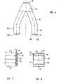
- Figure 6 shows schematically a front view of a further embodiment of the invention.
- the means for sensing the weight load of one of the frames and the adjustment means for the connection members for attaching a load or apparatus have been omitted.
- the frame shown in figure 6 has an upper trapezium shaped part 23 and two legs 24 having a rectangular cross-section and being bent such that the lower parts 25 are parallel and mainly vertical when the frames are in use.
- strip mountings 26 are provided at the upper side of trapezium 23 and at the lower side of the leg parts 25.
- One of these strip mountings has been shown in figure 7.
- This view shows two bars 27 and 28 on the leg parts 25 and its counter par 25' of the other frame. Bars 27 and 28 and the strip 29 interposed between the are made of stainless steel. Bar 27 is welded to leg part 25, which is made of normal construction steel. Any welding stresses, including those due to differing physical properties of the different materials are restricted to the contact region of the bar 27 with leg.. part 25.
- the strip 29 is welded at three sides of bars 27 and 28 indicated in figure 8 with- 30, 31 and 32. At the fourth side 33 of these bars no welding connection with strip 29 is made.
- stiffening plates 34 and 35 are welded to strip 29 along the sides 36 and 37.
- the strip 29 had a dimension (from 31 to the counterpart 31' of it at the other frame) of 180 mm and a dimension perpendicular thereto of 150 mm.
- the width of the free zones between the bars 27, 28 and the plates 34, 35 was 2 mm; the width of the bars 25 mm and consequently the length of the plates 34 or 35 was 126 mm.
- the bars 27 have to have a sufficient thickness to leave the plates 34 free from the frame parts 25 and 25'.
- the plates 34 and 35 have to have such a thickness that the strip between them can be exposed to compression forces in the direction from one set of bars 27, 28 toward the other without risk that the strip will kink or crack. For the same reason the free zones of the strip between the bars 27, 28 and the plates 34, 35 is so narrow that there no kinking or cracking of the strip will occur.
- the invention in first instance is suitable for agricultural purposes, where it is of great importance to know the weight of all sorts of things, as well of these which have to be bought or sold, such as crops,straw, hay or cattle, as of apparatus in order to know the weight of dispensed or collected materials. Higher dosage accuracy is highly desired in this field, as well with rearing or keeping cattle as for instance with fertilizing grounds. Therewith it is a great advantage of the invention that it is extremely light to transport and can be used with riding devices.
Landscapes
- Life Sciences & Earth Sciences (AREA)
- Soil Sciences (AREA)
- General Physics & Mathematics (AREA)
- Zoology (AREA)
- Engineering & Computer Science (AREA)
- Mechanical Engineering (AREA)
- Physics & Mathematics (AREA)
- Environmental Sciences (AREA)
- Agricultural Machines (AREA)
- Formation And Processing Of Food Products (AREA)
- Massaging Devices (AREA)
- Transplanting Machines (AREA)
- Weight Measurement For Supplying Or Discharging Of Specified Amounts Of Material (AREA)
- Sorting Of Articles (AREA)
Priority Applications (1)
| Application Number | Priority Date | Filing Date | Title |
|---|---|---|---|
| AT85201770T ATE39809T1 (de) | 1984-11-07 | 1985-10-31 | Vorrichtung zum wiegen. |
Applications Claiming Priority (2)
| Application Number | Priority Date | Filing Date | Title |
|---|---|---|---|
| NL8403387 | 1984-11-07 | ||
| NL8403387A NL8403387A (nl) | 1984-11-07 | 1984-11-07 | Inrichting voor het aan een trekker wegen van een werktuig of dergelijke. |
Publications (2)
| Publication Number | Publication Date |
|---|---|
| EP0181034A1 true EP0181034A1 (fr) | 1986-05-14 |
| EP0181034B1 EP0181034B1 (fr) | 1989-01-11 |
Family
ID=19844720
Family Applications (1)
| Application Number | Title | Priority Date | Filing Date |
|---|---|---|---|
| EP85201770A Expired EP0181034B1 (fr) | 1984-11-07 | 1985-10-31 | Dispositif de pesage |
Country Status (5)
| Country | Link |
|---|---|
| US (1) | US4722408A (fr) |
| EP (1) | EP0181034B1 (fr) |
| AT (1) | ATE39809T1 (fr) |
| DE (1) | DE3567353D1 (fr) |
| NL (1) | NL8403387A (fr) |
Cited By (3)
| Publication number | Priority date | Publication date | Assignee | Title |
|---|---|---|---|---|
| EP0222230A3 (en) * | 1985-11-09 | 1989-03-29 | De Dissel Beheer B.V. | Weighing device, particularly for attachment to a tractor |
| EP0713638A1 (fr) * | 1994-11-25 | 1996-05-29 | Maasland N.V. | Instrument de pesage |
| NL1008957C2 (nl) * | 1998-04-22 | 1999-10-25 | Maasland Nv | Inrichting voor het wegen van materiaal, zoals bijvoorbeeld kunstmest. |
Families Citing this family (4)
| Publication number | Priority date | Publication date | Assignee | Title |
|---|---|---|---|---|
| US5327708A (en) * | 1991-02-28 | 1994-07-12 | Gerrish Steven R | Crop testing and evaluation system |
| US5173079A (en) * | 1991-02-28 | 1992-12-22 | Gerrish Steven R | Crop testing and evaluation system |
| US5487702A (en) * | 1994-07-06 | 1996-01-30 | Harvestmaster, Inc. | Grain weighing and measuring system |
| DE60022307T2 (de) * | 2000-02-10 | 2006-06-08 | A.P. Laursen A/S | System zur vollautomatischen Dosierung in landwirtschaftlichen Maschinen |
Citations (2)
| Publication number | Priority date | Publication date | Assignee | Title |
|---|---|---|---|---|
| US2968475A (en) * | 1956-05-18 | 1961-01-17 | Beach Gauge Company | Scale mechanism |
| US3279550A (en) * | 1963-12-23 | 1966-10-18 | Donald J Kersten | Truck load measuring system |
Family Cites Families (1)
| Publication number | Priority date | Publication date | Assignee | Title |
|---|---|---|---|---|
| US3910363A (en) * | 1974-12-27 | 1975-10-07 | Allegany Technology Inc | Weighing device for fork lift truck |
-
1984
- 1984-11-07 NL NL8403387A patent/NL8403387A/nl not_active Application Discontinuation
-
1985
- 1985-10-31 EP EP85201770A patent/EP0181034B1/fr not_active Expired
- 1985-10-31 AT AT85201770T patent/ATE39809T1/de not_active IP Right Cessation
- 1985-10-31 DE DE8585201770T patent/DE3567353D1/de not_active Expired
-
1986
- 1986-02-14 US US06/829,496 patent/US4722408A/en not_active Expired - Fee Related
Patent Citations (2)
| Publication number | Priority date | Publication date | Assignee | Title |
|---|---|---|---|---|
| US2968475A (en) * | 1956-05-18 | 1961-01-17 | Beach Gauge Company | Scale mechanism |
| US3279550A (en) * | 1963-12-23 | 1966-10-18 | Donald J Kersten | Truck load measuring system |
Cited By (4)
| Publication number | Priority date | Publication date | Assignee | Title |
|---|---|---|---|---|
| EP0222230A3 (en) * | 1985-11-09 | 1989-03-29 | De Dissel Beheer B.V. | Weighing device, particularly for attachment to a tractor |
| EP0713638A1 (fr) * | 1994-11-25 | 1996-05-29 | Maasland N.V. | Instrument de pesage |
| NL1008957C2 (nl) * | 1998-04-22 | 1999-10-25 | Maasland Nv | Inrichting voor het wegen van materiaal, zoals bijvoorbeeld kunstmest. |
| EP0952435A1 (fr) * | 1998-04-22 | 1999-10-27 | Maasland N.V. | Dispositif pour le pesage de matériaux, tel que de l' engrais |
Also Published As
| Publication number | Publication date |
|---|---|
| EP0181034B1 (fr) | 1989-01-11 |
| NL8403387A (nl) | 1986-06-02 |
| DE3567353D1 (en) | 1989-02-16 |
| ATE39809T1 (de) | 1989-01-15 |
| US4722408A (en) | 1988-02-02 |
Similar Documents
| Publication | Publication Date | Title |
|---|---|---|
| US9775291B2 (en) | Gauge wheels for a multi-section agricultural header | |
| US7918076B2 (en) | Device for maintaining wing balance on a multi-section header | |
| CA3081598C (fr) | Organe de coupe a sections multiples avec lame de coupe de recolte souple | |
| US4956966A (en) | Header for a combine harvesting machine | |
| DE60204887T2 (de) | Mehrteiliges schneidwerk mit flexiblem gewächsschneidemesser | |
| US7790991B2 (en) | Crop weighing apparatus for an agricultural machine | |
| EP0181034B1 (fr) | Dispositif de pesage | |
| IE49688B1 (en) | Support and arrangement for tractor mounted machines | |
| CA2144325A1 (fr) | Appareil de mesure du rendement agricole | |
| CA1055322A (fr) | Indicateur pour plate-forme de moisonneuse-batteuse | |
| CA3026913C (fr) | Andaineuse comportant un couteau de recolte flexible | |
| US4879870A (en) | Mower with improved stiffening of the cutting bar | |
| CA2993727A1 (fr) | Collecteur agricole dote d'une commande de flottement | |
| EP0713638B1 (fr) | Instrument de pesage | |
| EP0625696A1 (fr) | Procédé et système pour peser une charge associée à un véhicule tracteur | |
| US3219128A (en) | Soil-tilling device, particularly a plow | |
| US3055322A (en) | Planter frame | |
| CN219478559U (zh) | 一种测产装置、测产系统以及联合收割机 | |
| EP0260750B1 (fr) | Faucheuse | |
| EP0952435A1 (fr) | Dispositif pour le pesage de matériaux, tel que de l' engrais | |
| EP3682722B1 (fr) | Outil amélioré pour le foin | |
| EP0218299A1 (fr) | Dispositif de pesage pouvant être monté entre un tracteur et un appareil porté par celui-ci | |
| US3984969A (en) | Baler pickup counterbalancing means | |
| EP1380203B1 (fr) | Appareil de mesure de débit massique pour une moissonneuse-batteuse | |
| AU2019204082B2 (en) | A crop harvesting header |
Legal Events
| Date | Code | Title | Description |
|---|---|---|---|
| PUAI | Public reference made under article 153(3) epc to a published international application that has entered the european phase |
Free format text: ORIGINAL CODE: 0009012 |
|
| AK | Designated contracting states |
Kind code of ref document: A1 Designated state(s): AT BE DE FR GB IT LU NL SE |
|
| 17P | Request for examination filed |
Effective date: 19860515 |
|
| 17Q | First examination report despatched |
Effective date: 19870825 |
|
| GRAA | (expected) grant |
Free format text: ORIGINAL CODE: 0009210 |
|
| AK | Designated contracting states |
Kind code of ref document: B1 Designated state(s): AT BE DE FR GB IT LU NL SE |
|
| REF | Corresponds to: |
Ref document number: 39809 Country of ref document: AT Date of ref document: 19890115 Kind code of ref document: T |
|
| REF | Corresponds to: |
Ref document number: 3567353 Country of ref document: DE Date of ref document: 19890216 |
|
| ITF | It: translation for a ep patent filed | ||
| ET | Fr: translation filed | ||
| PLBI | Opposition filed |
Free format text: ORIGINAL CODE: 0009260 |
|
| PG25 | Lapsed in a contracting state [announced via postgrant information from national office to epo] |
Ref country code: LU Free format text: LAPSE BECAUSE OF NON-PAYMENT OF DUE FEES Effective date: 19891031 Ref country code: GB Effective date: 19891031 Ref country code: BE Effective date: 19891031 Ref country code: AT Effective date: 19891031 |
|
| PG25 | Lapsed in a contracting state [announced via postgrant information from national office to epo] |
Ref country code: SE Effective date: 19891101 |
|
| 26 | Opposition filed |
Opponent name: HOOPMAN MACHINES B.V. Effective date: 19891006 |
|
| NLR1 | Nl: opposition has been filed with the epo |
Opponent name: HOOPMAN MACHINES B.V. |
|
| BERE | Be: lapsed |
Owner name: VAN DE VLIERT JAKOB Effective date: 19891031 |
|
| GBPC | Gb: european patent ceased through non-payment of renewal fee | ||
| PG25 | Lapsed in a contracting state [announced via postgrant information from national office to epo] |
Ref country code: FR Effective date: 19900629 |
|
| REG | Reference to a national code |
Ref country code: FR Ref legal event code: ST |
|
| PGFP | Annual fee paid to national office [announced via postgrant information from national office to epo] |
Ref country code: DE Payment date: 19931021 Year of fee payment: 9 |
|
| PGFP | Annual fee paid to national office [announced via postgrant information from national office to epo] |
Ref country code: NL Payment date: 19931031 Year of fee payment: 9 |
|
| EUG | Se: european patent has lapsed |
Ref document number: 85201770.6 Effective date: 19900705 |
|
| PG25 | Lapsed in a contracting state [announced via postgrant information from national office to epo] |
Ref country code: NL Effective date: 19950501 |
|
| NLV4 | Nl: lapsed or anulled due to non-payment of the annual fee | ||
| PG25 | Lapsed in a contracting state [announced via postgrant information from national office to epo] |
Ref country code: DE Effective date: 19950701 |
|
| APAC | Appeal dossier modified |
Free format text: ORIGINAL CODE: EPIDOS NOAPO |
|
| RDAG | Patent revoked |
Free format text: ORIGINAL CODE: 0009271 |
|
| STAA | Information on the status of an ep patent application or granted ep patent |
Free format text: STATUS: PATENT REVOKED |
|
| APAU | Communication from the board of appeal sent |
Free format text: ORIGINAL CODE: EPIDOS OBAP |
|
| 27W | Patent revoked |
Effective date: 19960215 |
|
| APAH | Appeal reference modified |
Free format text: ORIGINAL CODE: EPIDOSCREFNO |