EP0181108B1 - Procédé et appareillage d'oxydation - Google Patents
Procédé et appareillage d'oxydation Download PDFInfo
- Publication number
- EP0181108B1 EP0181108B1 EP85307518A EP85307518A EP0181108B1 EP 0181108 B1 EP0181108 B1 EP 0181108B1 EP 85307518 A EP85307518 A EP 85307518A EP 85307518 A EP85307518 A EP 85307518A EP 0181108 B1 EP0181108 B1 EP 0181108B1
- Authority
- EP
- European Patent Office
- Prior art keywords
- air
- oxygen
- catalyst
- enriched
- dense phase
- Prior art date
- Legal status (The legal status is an assumption and is not a legal conclusion. Google has not performed a legal analysis and makes no representation as to the accuracy of the status listed.)
- Expired - Lifetime
Links
- 238000000034 method Methods 0.000 title claims description 25
- 230000003647 oxidation Effects 0.000 title description 6
- 238000007254 oxidation reaction Methods 0.000 title description 6
- QVGXLLKOCUKJST-UHFFFAOYSA-N atomic oxygen Chemical compound [O] QVGXLLKOCUKJST-UHFFFAOYSA-N 0.000 claims description 117
- 239000001301 oxygen Substances 0.000 claims description 117
- 229910052760 oxygen Inorganic materials 0.000 claims description 117
- 239000003054 catalyst Substances 0.000 claims description 104
- 238000002485 combustion reaction Methods 0.000 claims description 30
- 239000000571 coke Substances 0.000 claims description 25
- 230000008929 regeneration Effects 0.000 claims description 17
- 238000011069 regeneration method Methods 0.000 claims description 17
- 238000005243 fluidization Methods 0.000 claims description 5
- 239000012071 phase Substances 0.000 description 54
- UGFAIRIUMAVXCW-UHFFFAOYSA-N Carbon monoxide Chemical compound [O+]#[C-] UGFAIRIUMAVXCW-UHFFFAOYSA-N 0.000 description 19
- JTJMJGYZQZDUJJ-UHFFFAOYSA-N phencyclidine Chemical class C1CCCCN1C1(C=2C=CC=CC=2)CCCCC1 JTJMJGYZQZDUJJ-UHFFFAOYSA-N 0.000 description 16
- 229930195733 hydrocarbon Natural products 0.000 description 15
- 150000002430 hydrocarbons Chemical class 0.000 description 15
- 230000000694 effects Effects 0.000 description 14
- 239000007789 gas Substances 0.000 description 14
- 239000004215 Carbon black (E152) Substances 0.000 description 11
- 238000004523 catalytic cracking Methods 0.000 description 11
- 239000003546 flue gas Substances 0.000 description 11
- OKTJSMMVPCPJKN-UHFFFAOYSA-N Carbon Chemical compound [C] OKTJSMMVPCPJKN-UHFFFAOYSA-N 0.000 description 9
- 229910052799 carbon Inorganic materials 0.000 description 9
- 229910002091 carbon monoxide Inorganic materials 0.000 description 8
- 238000006243 chemical reaction Methods 0.000 description 7
- 238000004231 fluid catalytic cracking Methods 0.000 description 7
- 239000000203 mixture Substances 0.000 description 7
- 238000005336 cracking Methods 0.000 description 6
- 239000002245 particle Substances 0.000 description 5
- CURLTUGMZLYLDI-UHFFFAOYSA-N Carbon dioxide Chemical compound O=C=O CURLTUGMZLYLDI-UHFFFAOYSA-N 0.000 description 4
- 230000001668 ameliorated effect Effects 0.000 description 2
- 229910002092 carbon dioxide Inorganic materials 0.000 description 2
- 239000001569 carbon dioxide Substances 0.000 description 2
- 230000007812 deficiency Effects 0.000 description 2
- 238000009826 distribution Methods 0.000 description 2
- 239000007788 liquid Substances 0.000 description 2
- 238000000926 separation method Methods 0.000 description 2
- 238000003860 storage Methods 0.000 description 2
- MYMOFIZGZYHOMD-UHFFFAOYSA-N Dioxygen Chemical compound O=O MYMOFIZGZYHOMD-UHFFFAOYSA-N 0.000 description 1
- UFHFLCQGNIYNRP-UHFFFAOYSA-N Hydrogen Chemical compound [H][H] UFHFLCQGNIYNRP-UHFFFAOYSA-N 0.000 description 1
- 206010021143 Hypoxia Diseases 0.000 description 1
- 230000003197 catalytic effect Effects 0.000 description 1
- 238000010276 construction Methods 0.000 description 1
- 239000000356 contaminant Substances 0.000 description 1
- 238000001816 cooling Methods 0.000 description 1
- 230000008021 deposition Effects 0.000 description 1
- 238000010586 diagram Methods 0.000 description 1
- 239000012530 fluid Substances 0.000 description 1
- 239000007792 gaseous phase Substances 0.000 description 1
- 239000001257 hydrogen Substances 0.000 description 1
- 229910052739 hydrogen Inorganic materials 0.000 description 1
- 238000009434 installation Methods 0.000 description 1
- 238000012423 maintenance Methods 0.000 description 1
- VUZPPFZMUPKLLV-UHFFFAOYSA-N methane;hydrate Chemical compound C.O VUZPPFZMUPKLLV-UHFFFAOYSA-N 0.000 description 1
- 238000012544 monitoring process Methods 0.000 description 1
- 230000001590 oxidative effect Effects 0.000 description 1
- 230000002035 prolonged effect Effects 0.000 description 1
- 238000009827 uniform distribution Methods 0.000 description 1
- 239000002912 waste gas Substances 0.000 description 1
- XLYOFNOQVPJJNP-UHFFFAOYSA-N water Substances O XLYOFNOQVPJJNP-UHFFFAOYSA-N 0.000 description 1
- 229910001868 water Inorganic materials 0.000 description 1
Images


Classifications
-
- B—PERFORMING OPERATIONS; TRANSPORTING
- B01—PHYSICAL OR CHEMICAL PROCESSES OR APPARATUS IN GENERAL
- B01J—CHEMICAL OR PHYSICAL PROCESSES, e.g. CATALYSIS OR COLLOID CHEMISTRY; THEIR RELEVANT APPARATUS
- B01J38/00—Regeneration or reactivation of catalysts, in general
- B01J38/04—Gas or vapour treating; Treating by using liquids vaporisable upon contacting spent catalyst
- B01J38/12—Treating with free oxygen-containing gas
- B01J38/30—Treating with free oxygen-containing gas in gaseous suspension, e.g. fluidised bed
-
- B—PERFORMING OPERATIONS; TRANSPORTING
- B01—PHYSICAL OR CHEMICAL PROCESSES OR APPARATUS IN GENERAL
- B01J—CHEMICAL OR PHYSICAL PROCESSES, e.g. CATALYSIS OR COLLOID CHEMISTRY; THEIR RELEVANT APPARATUS
- B01J23/00—Catalysts comprising metals or metal oxides or hydroxides, not provided for in group B01J21/00
- B01J23/90—Regeneration or reactivation
-
- B—PERFORMING OPERATIONS; TRANSPORTING
- B01—PHYSICAL OR CHEMICAL PROCESSES OR APPARATUS IN GENERAL
- B01J—CHEMICAL OR PHYSICAL PROCESSES, e.g. CATALYSIS OR COLLOID CHEMISTRY; THEIR RELEVANT APPARATUS
- B01J38/00—Regeneration or reactivation of catalysts, in general
- B01J38/04—Gas or vapour treating; Treating by using liquids vaporisable upon contacting spent catalyst
- B01J38/12—Treating with free oxygen-containing gas
- B01J38/14—Treating with free oxygen-containing gas with control of oxygen content in oxidation gas
-
- C—CHEMISTRY; METALLURGY
- C10—PETROLEUM, GAS OR COKE INDUSTRIES; TECHNICAL GASES CONTAINING CARBON MONOXIDE; FUELS; LUBRICANTS; PEAT
- C10G—CRACKING HYDROCARBON OILS; PRODUCTION OF LIQUID HYDROCARBON MIXTURES, e.g. BY DESTRUCTIVE HYDROGENATION, OLIGOMERISATION, POLYMERISATION; RECOVERY OF HYDROCARBON OILS FROM OIL-SHALE, OIL-SAND, OR GASES; REFINING MIXTURES MAINLY CONSISTING OF HYDROCARBONS; REFORMING OF NAPHTHA; MINERAL WAXES
- C10G11/00—Catalytic cracking, in the absence of hydrogen, of hydrocarbon oils
- C10G11/14—Catalytic cracking, in the absence of hydrogen, of hydrocarbon oils with preheated moving solid catalysts
- C10G11/18—Catalytic cracking, in the absence of hydrogen, of hydrocarbon oils with preheated moving solid catalysts according to the "fluidised-bed" technique
- C10G11/182—Regeneration
-
- F—MECHANICAL ENGINEERING; LIGHTING; HEATING; WEAPONS; BLASTING
- F23—COMBUSTION APPARATUS; COMBUSTION PROCESSES
- F23C—METHODS OR APPARATUS FOR COMBUSTION USING FLUID FUEL OR SOLID FUEL SUSPENDED IN A CARRIER GAS OR AIR
- F23C10/00—Fluidised bed combustion apparatus
- F23C10/02—Fluidised bed combustion apparatus with means specially adapted for achieving or promoting a circulating movement of particles within the bed or for a recirculation of particles entrained from the bed
- F23C10/04—Fluidised bed combustion apparatus with means specially adapted for achieving or promoting a circulating movement of particles within the bed or for a recirculation of particles entrained from the bed the particles being circulated to a section, e.g. a heat-exchange section or a return duct, at least partially shielded from the combustion zone, before being reintroduced into the combustion zone
- F23C10/08—Fluidised bed combustion apparatus with means specially adapted for achieving or promoting a circulating movement of particles within the bed or for a recirculation of particles entrained from the bed the particles being circulated to a section, e.g. a heat-exchange section or a return duct, at least partially shielded from the combustion zone, before being reintroduced into the combustion zone characterised by the arrangement of separation apparatus, e.g. cyclones, for separating particles from the flue gases
Definitions
- the present invention relates to an oxidation process and apparatus.
- it relates to a process and apparatus for the oxidative regeneration of a coke-contaminated catalyst, particularly one used in the fluidised bed catalytic cracking of hydrocarbons.
- the fluid catalytic cracking of a hydrocarbon feedstock is an important oil refinery operation for producing petrol (gasoline) and other relatively light hydrocarbon products from heavier hydrocarbons such as vacuum gas oil.
- the process typically comprises contacting the preheated feedstock with a cracking catalyst under cracking conditions to produce cracked hydrocarbon vapours.
- Coke i.e. very heavy hydrocarbon deposits typically including 7% by weight of hydrogen
- the effect of this deposition is to reduce the activity of the catalyst. It is therefore necessary to regenerate the catalyst.
- the cracked hydrocarbon vapours are separated from the coke-contaminated catalyst and recovered as product essentially free from entrained catalyst. Volatile hydrocarbons are stripped from the spent catalyst by contact with stripping vapours in a striping zone.
- the resulting catalyst is then regenerated in a fluidised bed by burning the coke that adheres to its surfaces. Air is supplied to the regenerator so as to provide the necessary oxygen for the regeneration.
- the conditions that are employed in the regenerator are such that most and preferably substantially all of the coke is removed by oxidation from the surface of the catalyst.
- the regenerated catalyst is withdrawn from the regenerator and returned to the reactor. There is thus continuous circulation of spent catalyst from the reactor to the regenerator and regenerated catalyst from the regenerator to the reactor. Simultaneously, the hydrocarbon feedstock is continuously fed into the reactor.
- the regenerator comprises a large, vertical, cylindrical vessel in which the coke-contaminated catalyst is maintained in a fluidised state by the upward passage therethrough of air.
- the fluidised catalyst forms a dense phase of a fluidised bed in a lower portion of the vessel and a dilute phase in an upper portion of the vessel.
- the flue gas from the dilute phase passes through cyclone separation means located in the regenerator vessel so as to extract suspended catalyst from the flue gas.
- cyclone separation means located in the regenerator vessel so as to extract suspended catalyst from the flue gas.
- cyclone separation means located in the regenerator vessel so as to extract suspended catalyst from the flue gas.
- the air that fluidises the bed also serves the purpose of supporting combustion of the coke that adheres to the particles of catalyst. It is typically supplied to the regenerator vessel through one or more distributor pipes located in the dense phase of the fluidised bed.
- the regenerator employs a single main annular distributor with air distributing nozzles facing upwardly and/or downwardly.
- arcuate distributors are employed, and are typically arranged so that they all lie on the same annulus.
- One example of the present invention is particularly concerned with the operation of regenerators of this type.
- an inner distributor or distributors for distributing air to the centre of the dense phase of the fluidised bed to ensure that no slumping of the bed takes place in the central region.
- this air amounts to about 5-15% by volume of that supplied to the main air distributors.
- the oxidation of the coke contaminant on the catalyst is an exothermic process. Accordingly, fluid catalytic cracking plant is designed so that the heat generated in the regenerator is employed in the reactor.
- Relatively hot catalyst is fed back into the reactor from the regenerator to effect this transfer of heat.
- the catalyst will pass into the reactor vessel via a riser or transfer line. It is to be appreciated that in some plant the catalytic cracking reaction takes place predominantly in the riser and is completed in the reactor vessel.
- the burning of the coke is able to satisfy all the heat requirements of the catalytic cracking unit, although if desired additional preheating of the feedstock may be provided as well by means of a separately fired preheater.
- the arrangement is such that there is always a heat balance between the regenerator and the reactor.
- a common air main is used to supply all the air requirements of the regenerator.
- This main may be supplied with air from one or more blowers. Therefore, the case sometimes arises that the maximum output of the blower or blowers is reached.
- Another limitation that can arise in practice is that the maximum fluidising velocity through the bed may be reached above which an excessive and undesirable amount of elutriation of catalyst from the dense phase of the bed occurs.
- EP-A-60 050 discloses that in a fluid catalytic cracking process, the regeneration temperature can be eliminated as an operating constraint, and the amount of residual carbon on the regenerated catalyst can be reduced by increasing the oxygen content of the regeneration catalyst and cooling the catalyst to maintain the regeneration temperature.
- the present invention is particularly concerned with two other kinds of limitation that arise.
- the regenerator is of the aforesaid kind which has a plurality of distributors for introducing combustion air from a common air main into the dense phase of the fluidised bed
- a balancing valve is provided for each main distributor of combustion air. This enables the air supplied by each such distributor through the bed to be balanced with the air supplied from the other distributors so as to maintain uniform combustion throughout the bed.
- the balancing valves need to be fully opened.
- Another problem that can arise is that when the requirements for combustion air become a maximum in the regenerator, inadequate air may be supplied to a so-called secondary or "fluffing air” distributor or distributors that supply air to the centre of the bed and that non-uniform combustion of the coke or slumping of the bed can occur at the centre of the dense phase.
- US-A-4 035 153 discloses a catalyst regeneration process in which trim gas is supplied separately below the fluidised dense phase bed so as to cure oxygen deficiency in that bed which may arise notwithstanding the supply of primary regeneration gas.
- the invention also provides apparatus for the regeneration of a coke-contaminated catalyst, comprising:
- the process and apparatus according to the present invention makes it possible to control the supply of air and oxygen (or oxygen-enriched air) to the dense phase of a fluidised bed of the catalyst so as to maintain uniform combustion conditions throughout.
- Such uniform combustion conditions manifest themselves in relatively even temperature rises in each cyclone separator means and in relatively uniform gas compositions in the flue gas entering and leaving such cyclone separators. They also manifest themselves in relatively uniform gas compositions in the flue gas entering and leaving such cyclone separators. They also manifest themselves in relatively uniform residual carbon levels on the catalyst returned to the reactor.
- each distributor to which oxygen or oxygen-enriched air is supplied may typically receive such gas at such a rate that the air also supplied thereto is enriched in oxygen by up to 6% in volume.
- operation of the control valves associated with the oxygen or oxygen-enriched air supply means may be effected automatically.
- the controlling parameter may for example be the temperature of the flue gas leaving the cyclone separators associated with each main distributor, or the composition of the gas leaving such separators, for example, its oxygen or carbon monoxide concentration. It should be noted however that the control means must always take account of the, maximum permissible oxygen concentration at any point in the plant.
- the oxygen or oxygen-enriched air may beneficially be applied to an existing fluid catalytic cracking plant, which the regenerator is intended to produce regenerated catalyst with 0.1% by weight or less of residual coke (such a plant is often referred to as a "total burn" plant).
- oxygen or oxygen-enriched air may also help to eliminate any problem with excessive temperature rises being created in the cyclone separators.
- the use of oxygen or oxygen enriched air to increase the partial pressure of oxygen in the reactor will help to increase the percentage of carbon that is burnt off in a given time in the regenerator.
- the regenerator will be operated with distinct dense and dilute phases with an interface therebetween.
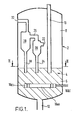
- a regenerator vessel 2 is adapted to operate at pressures above atmospheric and has in it a fluidised bed 4 of catalyst undergoing regeneration.
- the fluidised bed 4 comprises a lower dense phase 6 of catalyst undergoing regeneration and an upper dilute phase 8 of such catalyst.
- the reactor is situated vertically above the regenerator 2.
- At the bottom of the regenerator vessel 2 is an outlet 12 for regenerated catalyst.
- the necessary catalyst flow control valves in the pipe 10 and outlet 12 are not shown. In practice, these valves will be open to extents such that the rate of infeed of catalyst into the regenerator 2 will equal the rate at which regenerated catalyst is withdrawn or extracted therefrom.
- main air distributors 16(a), 16(b) and 16(c) are located in the dense phase 6 of the fluidised bed 4. As shown in Figure 2, the main air distributors 16 are located substantially in the same plane and are juxtaposed such that they all lie on the same annulus. Each distributor 16 has nozzles (not shown) pointing upwardly and/or downwardly so as to ensure a uniform distribution of air throughout the dense phase 6 of the fluidised bed 4. Located within the annulus on which the three main air distributors 16 lie are three arcuate secondary air distributors 18(a), 18(b) and 18(c). The distributors 18 all lie on the same annulus as each other, which annulus is coaxial with the annulus on which the distributor 16 lies (although this is not essential). The distributors 18 have air distribution nozzles (not shown) pointing upwardly and/or downwardly so as to facilitate uniform fluidisation of the bed in its central region.
- the regenerator vessel 2 is also provided with means for extracting catalyst from the flue gas so as to minimise the quantity of catalyst which is carried out of the regenerator 2 with such flue gas.
- This means includes six primary cyclones 20(a) to 20(f). Only one of these cyclones is illustrated in Figure 1 of the accompanying drawings, for purposes of ease of illustration.
- Each cyclone 20 has a downcomer 24 through which catalyst separated from the gas entering the cyclones 20 is returned to the dense phase 6 of the fluidised bed 4.
- the cyclones 20 all have outlets 26 each of which leads to a respective secondary cyclone 28.
- Each secondary cyclone 28 has a downcomer 30 from which catalyst is returned to the dense phase 6 of the fluidised bed 4 and an outlet 32 for gas substantially free of catalyst.
- Each outlet 32 communicates with a stack (not shown) through which waste gas can be discharged from process.
- an air main 34 that communicates with an air blower 46.
- the air main 34 also communicates with three primary air supply conduits 36(a), 36(b) and 36(c) each of which terminates in a respective main air distributor 16.
- Balancing valves 42(a), 42(b) and 42(c) are located in the air supply conduits 36(a), 36(b) and 36(c) respectively.
- the air main 34 also communicates with three secondary air supply conduits 40(a), 40(b) and 40(c), each of which in turn communicates with a respective one of the air distributors 18(a), 18(b) and 18(c).
- Balancing valves 44(a), 44(b) and 44(c) are located in the conduits 40(a), 40(b) and 40(c) respectively.
- the balancing vlaves 42 and 44 are all operable to facilitate the achievement of a uniform air distribution throughout the dense phase of the fluidised bed and hence a uniform combustion of the coke adhering to the surface of the contaminated catalyst particles.
- the apparatus shown in Figures 1 and 2 also includes an oxygen supply main 48 communicating with a source of commerically pure oxygen (not shown).
- This source can comprise a plant for separating oxygen and air, or one or more thermally-insulated storage vessels that hold oxygen in its liquid state and that are fitted with vaporisers so as to vaporise the oxygen and supply gaseous oxygen to the main 48.
- Three oxygen supply conduits 50(a), 50(b) and 50(c) extend from the oxygen supply main 48 and terminate respectively in the air supply conduits 36(a), 36(b), and 36(c) at respective regions downstream of the balancing valves 42.
- Flow control valves 52(a), 52(b) and 52(c) are located in the oxygen supply conduits 50(a), 50(b) and 50(c) respectively.
- the valves 52 are operable so as to enable different oxygen flow rates from the three air supply conduits 36 to be set.
- a fluidised bed of coke-contaminated catalyst to be regenerated is established in the regenerator vessel 2.
- the fluidised bed 4 has a dense phase 6 and a dilute phase 8.
- Air is supplied to the bed from the blower 46 via the distributors 16 and 18.
- Hot coke-contaminated catalyst typically at a temperature in the range 450 ⁇ 500°C is fed from the hydrocarbon stripper (not shown) of the fluidised bed catalytic cracking reactor (not shown) to the pipe 10 and thus flows down this pipe into the dense phase 6 of the fluidised bed 4.
- the exit from this pipe 10 is positioned well away from the distributors 16 and 18 so as to prevent any common interference between the air issuing from the distributors 16 and 18 and the catalyst issuing from the pipe 10.
- the coke on the surface of the contaminated catalyst particles is oxidised by reaction with the oxygen in the air supplied to the dense phase 6 of the fluidised bed 4 from the distributors 16 and 18.
- a mixture of carbon monoxide, carbon dioxide and water vapour is thus formed.
- the proportions of carbon monoxide and carbon dioxide in the mixture depends on the conditions under which the fluidised bed 4 is operated. These conditions will include the amount of excess air that is supplied, the temperature of the bed, the average residence time of the catalyst particles in the bed and the amount of coke deposited on the catalyst during the cracking process, amongst other factors. Typically conditions are arranged so as to give substantially a "total burn" of coke.
- any carbon monoxide that does enter the dilute phase 8 of the bed will tend to undergo after burning with any excess oxygen here and in the cyclone separators 20 and 28 that are operated continuously throughout the operation of the regenerator 2 so as to feed back catalyst from the dilute phase to the dense phase of the fluidised bed.
- the dense phase of the bed will be operated at a temperature in the range 700-750°C.
- the air blower 46 is operated at an appropriate rpm and the balancing valves 42 and 44 are set so as to give uniform conditions throughout the dense phase of the bed. Whether there is a need to supply oxygen from the oxygen supply main 48 will depend on whether the air supply system is able to cope with the demands placed on it. As has been aforementioned, over recent years there has been a tendency to increase the demands placed on regenerators such as those shown in Figures 1 and 2.
- the balancing valves 42 are therefore opened wider to allow the extra air to flow through. (Since only about 5-15% of the total air entering the fluidised bed enters through the distributors 18, the setting of the balancing valves 44 controlling the air flow to these distributors is less critical.) Indeed, it has been found that in practice the valves 42 have in some instances had to be fully opened in order to meet the total requirements for air in the bed. It is at this stage that differential or uneven flows along the conduits 36(a), 36(b) and 36(c) will become critical.
- Such uneven flows may be caused by blockages in one or more of the air distributors 16 or by different pressure drops therealong or by a combination of both factors. It has been found in practice that a situation may be reached in which, with the balancing valves 42 fully open, the air supply to one part of the bed say through the distributor 16(a) is inadequate to maintain the necessary "total burn” oxidation conditions in the part of the bed served by that distributor while the total rate of supply of air would otherwise be adequate to maintain total burn conditions. This means that the rate of supply to at least one of the distributors 16(b) and 16(c) is above the minimum necessary to maintain total burn in the parts of the beds served by these two distributors. There are two main consequences of this phenomenon.
- the selective enrichment in oxygen of the air supplied to one or more of the distributors 16 in accordance with the present invention enables the above mentioned problem to be ameliorated.
- the air flow through the distributor 16(a) is some 5,000 standard cubic feet per hour less than it should be while that through the distributor 16(b) is substantially that required to provide total burn conditions and that through the distributor 16(c) is some 5,000 cubic feet per hour in excess of the minimum rate required to maintain total burn conditions in the part of the regenerator that it serves.
- oxygen is supplied to the air supply conduit 36(a) at a rate in the order of 1,100 standard cubic feet per hour from the oxygen supply conduit 50(a) and the balancing valve 42(a) reset so as to reduce the flow of air therethrough in order to re-establish uniform total burn throughout the dense phase 6 of the bed 4.
- oxygen might be supplied to the air supply conduit 36(b) at a rate substantially less than that at which oxygen is supplied to the conduit 36(a).
- no oxygen is supplied to conduit 36(c).
- the oxygen flow control valves 52 may be controlled automatically by means of, for example, devices for monitoring, say, the oxygen concentration in the flue gas leaving the respective cyclones 28.
- the relationship between such oxygen concentration (and other parameters such as the exhaust temperature and carbon monoxide concentration) associated with each resepective cyclone on the one hand, and the flow rate of oxygen molecules into the dense phase through each respective main air distributor on the other hand may be determined empirically and an automatic control system calibrated accordingly in order to maintain oxygen flows into the dense phase such that substantially uniform combustion conditions are maintained in the dense phase.
- the control system will typically include an override which limits the maximum degree of oxygen enrichment which can be obtained in any one distributor. Typically this limit will prevent any local oxygen concentration greater than say 27% by volume from being created.
- FIGs 3 and 4 illustrate the regenerator of a different kind of catalytic cracking plant.
- parts of the regenerators respectively shown in Figures 1 and 2 on the one hand, and Figures 3 and 4, on the other hand, are indicated by the same reference numerals.
- a first difference is that the catalyst inlet pipe 10 enters the regenerator shown in Figures 3 and 4 at a location near its bottom. This is because the regenerator shown in Figures 3 and 4 is associated with a reactor (not shown) which is located side-by-side with the regenerator rather than above it as in the example described with reference to Figures 1 and 2.
- a second main difference is that instead of employing three main air distributors that extend arcuately and three similar secondary air distributors as shown in Figures 1 and 2, the regenerator shown in Figures 3 and 4 has a single annular main air distributor 62 and a single secondary air distributor 64.
- the air main 34 communicates with two air conduits 66 and 68.
- the air conduit 66 terminates in the distributor 62 and the air conduit 68 terminates in the distributor 64.
- air flow control valves 70 and 72 are located in the conduits 66 and 68 respectively.
- the third difference between the regenerator shown in Figures 3 and 4 and that shown in Figures 1 and 2 resides in the oxygen supply system.
- the air in the main 34 may additionally be enriched in oxygen. This will mean that the air streams supplied through the distributor 62 and 64 will both be enriched in oxygen, but the degree of oxygen enrichment in the air supplied to the latter distributor will be greater than that supplied to the former.
Landscapes
- Chemical & Material Sciences (AREA)
- Engineering & Computer Science (AREA)
- Organic Chemistry (AREA)
- Chemical Kinetics & Catalysis (AREA)
- Materials Engineering (AREA)
- Oil, Petroleum & Natural Gas (AREA)
- Combustion & Propulsion (AREA)
- Mechanical Engineering (AREA)
- General Engineering & Computer Science (AREA)
- General Chemical & Material Sciences (AREA)
- Production Of Liquid Hydrocarbon Mixture For Refining Petroleum (AREA)
Claims (11)
Applications Claiming Priority (2)
| Application Number | Priority Date | Filing Date | Title |
|---|---|---|---|
| GB848428395A GB8428395D0 (en) | 1984-11-09 | 1984-11-09 | Oxidation process |
| GB8428395 | 1984-11-09 |
Publications (3)
| Publication Number | Publication Date |
|---|---|
| EP0181108A2 EP0181108A2 (fr) | 1986-05-14 |
| EP0181108A3 EP0181108A3 (en) | 1987-02-04 |
| EP0181108B1 true EP0181108B1 (fr) | 1990-12-19 |
Family
ID=10569504
Family Applications (1)
| Application Number | Title | Priority Date | Filing Date |
|---|---|---|---|
| EP85307518A Expired - Lifetime EP0181108B1 (fr) | 1984-11-09 | 1985-10-17 | Procédé et appareillage d'oxydation |
Country Status (6)
| Country | Link |
|---|---|
| EP (1) | EP0181108B1 (fr) |
| JP (1) | JPS62283189A (fr) |
| AU (1) | AU4948785A (fr) |
| DE (1) | DE3580970D1 (fr) |
| GB (1) | GB8428395D0 (fr) |
| ZA (1) | ZA858465B (fr) |
Cited By (2)
| Publication number | Priority date | Publication date | Assignee | Title |
|---|---|---|---|---|
| DE4041976A1 (de) * | 1990-12-21 | 1992-06-25 | Petrolchemie Und Kraftstoffe A | Verfahren und vorrichtung zum koksabbrand von katalysatoren im rezirkulierenden fliessbett |
| EP3423182B1 (fr) * | 2016-02-29 | 2025-07-30 | Uop Llc | Procédé et appareil de fluidification de catalyseur usé |
Families Citing this family (5)
| Publication number | Priority date | Publication date | Assignee | Title |
|---|---|---|---|---|
| DE3641773A1 (de) * | 1986-12-06 | 1988-06-09 | Metallgesellschaft Ag | Verfahren zur katalytischen reduktion von in einem gas enthaltenem no |
| CA2156464C (fr) * | 1994-09-30 | 1999-07-20 | Raghu K. Menon | Reduction des emissions produites par les regenerateurs par craquage catalytique fluide |
| FI125496B (fi) * | 2009-08-17 | 2015-10-30 | Valmet Technologies Oy | Menetelmä ja järjestely palamisolosuhteiden optimoimiseksi leijukerroskattilassa |
| US9202503B2 (en) | 2013-01-15 | 2015-12-01 | HGST Netherlands B.V. | Magnetic media with a low molecular weight lubricating layer for use in head/media contact detection |
| JP2022166720A (ja) * | 2021-04-21 | 2022-11-02 | 出光興産株式会社 | 流動接触分解装置の運転方法及び流動接触分解装置 |
Family Cites Families (2)
| Publication number | Priority date | Publication date | Assignee | Title |
|---|---|---|---|---|
| US4035153A (en) * | 1976-05-07 | 1977-07-12 | Texaco Inc. | Fluidized cracking catalyst regeneration apparatus |
| US4370222A (en) * | 1981-03-02 | 1983-01-25 | Mobil Oil Corporation | FCC Regeneration |
-
1984
- 1984-11-09 GB GB848428395A patent/GB8428395D0/en active Pending
-
1985
- 1985-10-17 DE DE8585307518T patent/DE3580970D1/de not_active Expired - Fee Related
- 1985-10-17 EP EP85307518A patent/EP0181108B1/fr not_active Expired - Lifetime
- 1985-11-04 ZA ZA858465A patent/ZA858465B/xx unknown
- 1985-11-08 AU AU49487/85A patent/AU4948785A/en not_active Abandoned
- 1985-11-09 JP JP60251822A patent/JPS62283189A/ja active Granted
Cited By (2)
| Publication number | Priority date | Publication date | Assignee | Title |
|---|---|---|---|---|
| DE4041976A1 (de) * | 1990-12-21 | 1992-06-25 | Petrolchemie Und Kraftstoffe A | Verfahren und vorrichtung zum koksabbrand von katalysatoren im rezirkulierenden fliessbett |
| EP3423182B1 (fr) * | 2016-02-29 | 2025-07-30 | Uop Llc | Procédé et appareil de fluidification de catalyseur usé |
Also Published As
| Publication number | Publication date |
|---|---|
| EP0181108A3 (en) | 1987-02-04 |
| DE3580970D1 (de) | 1991-01-31 |
| AU4948785A (en) | 1986-05-15 |
| GB8428395D0 (en) | 1984-12-19 |
| JPH0582878B2 (fr) | 1993-11-22 |
| JPS62283189A (ja) | 1987-12-09 |
| EP0181108A2 (fr) | 1986-05-14 |
| ZA858465B (en) | 1986-06-25 |
Similar Documents
| Publication | Publication Date | Title |
|---|---|---|
| US4849091A (en) | Partial CO combustion with staged regeneration of catalyst | |
| US4419221A (en) | Cracking with short contact time and high temperatures | |
| US5455010A (en) | FCC process with total catalyst blending | |
| US6835302B2 (en) | FCC process and apparatus with automatic catalyst recycle control | |
| CA2437649C (fr) | Regenerateur de catalyseurs avec puits central | |
| US7026262B1 (en) | Apparatus and process for regenerating catalyst | |
| EP1413621B1 (fr) | Récupération de catalyseur d'un effluent de craquage catalytique fluide contenant des oléfines légères | |
| US4167492A (en) | Spent-catalyst combustion regeneration process with recycle of hot regenerated catalyst and spent catalyst | |
| EP0457540B1 (fr) | Système de distribution de catalyseur d'un régénérateur d'une unité FCC | |
| US6680030B2 (en) | Stripping process with horizontal baffles | |
| US4356082A (en) | Heat balance in FCC process | |
| US3197284A (en) | Fluidized catalytic hydrogen production | |
| US10960390B2 (en) | Partial burn combustor regenerator | |
| EP0181108A2 (fr) | Procédé et appareillage d'oxydation | |
| US4724065A (en) | Hydrocarbon conversion with hot and cooled regenerated catalyst in series | |
| EP0309244B1 (fr) | Régénération de craquage catalytique à lit fluide avec un séparateur de catalyseur consommé | |
| US4454022A (en) | Decoking method | |
| GB2166663A (en) | Oxidation process and apparatus | |
| US3923642A (en) | Catalytic hydrocarbon conversion process and apparatus | |
| US4370222A (en) | FCC Regeneration | |
| WO2003083014A1 (fr) | Procede et appareil fcc de regulation automatique du recyclage du catalyseur | |
| EP0236055A2 (fr) | Procédé de traitement d'hydrocarbures | |
| EP0129621B1 (fr) | Appareillage et procédé pour le craquage catalytique fluidisé d'hydrocarbures et régénération du catalyseur | |
| EP0023402A1 (fr) | Craquage catalytique fluidisé avec des gradients de température et de composition réduits dans la phase diluée du régénérateur | |
| US3996013A (en) | Catalytic hydrocarbon conversion apparatus |
Legal Events
| Date | Code | Title | Description |
|---|---|---|---|
| PUAI | Public reference made under article 153(3) epc to a published international application that has entered the european phase |
Free format text: ORIGINAL CODE: 0009012 |
|
| AK | Designated contracting states |
Kind code of ref document: A2 Designated state(s): BE DE FR NL |
|
| PUAL | Search report despatched |
Free format text: ORIGINAL CODE: 0009013 |
|
| AK | Designated contracting states |
Kind code of ref document: A3 Designated state(s): BE DE FR NL |
|
| 17P | Request for examination filed |
Effective date: 19871001 |
|
| 17Q | First examination report despatched |
Effective date: 19881104 |
|
| GRAA | (expected) grant |
Free format text: ORIGINAL CODE: 0009210 |
|
| AK | Designated contracting states |
Kind code of ref document: B1 Designated state(s): BE DE FR NL |
|
| ET | Fr: translation filed | ||
| REF | Corresponds to: |
Ref document number: 3580970 Country of ref document: DE Date of ref document: 19910131 |
|
| ITF | It: translation for a ep patent filed | ||
| PLBE | No opposition filed within time limit |
Free format text: ORIGINAL CODE: 0009261 |
|
| STAA | Information on the status of an ep patent application or granted ep patent |
Free format text: STATUS: NO OPPOSITION FILED WITHIN TIME LIMIT |
|
| 26N | No opposition filed | ||
| PGFP | Annual fee paid to national office [announced via postgrant information from national office to epo] |
Ref country code: FR Payment date: 20011002 Year of fee payment: 17 |
|
| PGFP | Annual fee paid to national office [announced via postgrant information from national office to epo] |
Ref country code: DE Payment date: 20011004 Year of fee payment: 17 |
|
| PGFP | Annual fee paid to national office [announced via postgrant information from national office to epo] |
Ref country code: NL Payment date: 20011009 Year of fee payment: 17 |
|
| PGFP | Annual fee paid to national office [announced via postgrant information from national office to epo] |
Ref country code: BE Payment date: 20011025 Year of fee payment: 17 |
|
| PG25 | Lapsed in a contracting state [announced via postgrant information from national office to epo] |
Ref country code: BE Free format text: LAPSE BECAUSE OF NON-PAYMENT OF DUE FEES Effective date: 20021031 |
|
| BERE | Be: lapsed |
Owner name: THE *BOC GROUP P.L.C. Effective date: 20021031 |
|
| PG25 | Lapsed in a contracting state [announced via postgrant information from national office to epo] |
Ref country code: NL Free format text: LAPSE BECAUSE OF NON-PAYMENT OF DUE FEES Effective date: 20030501 Ref country code: DE Free format text: LAPSE BECAUSE OF NON-PAYMENT OF DUE FEES Effective date: 20030501 |
|
| PG25 | Lapsed in a contracting state [announced via postgrant information from national office to epo] |
Ref country code: FR Free format text: LAPSE BECAUSE OF NON-PAYMENT OF DUE FEES Effective date: 20030630 |
|
| NLV4 | Nl: lapsed or anulled due to non-payment of the annual fee |
Effective date: 20030501 |
|
| REG | Reference to a national code |
Ref country code: FR Ref legal event code: ST |