EP0181147A2 - Dispositif de pesage - Google Patents
Dispositif de pesage Download PDFInfo
- Publication number
- EP0181147A2 EP0181147A2 EP85307853A EP85307853A EP0181147A2 EP 0181147 A2 EP0181147 A2 EP 0181147A2 EP 85307853 A EP85307853 A EP 85307853A EP 85307853 A EP85307853 A EP 85307853A EP 0181147 A2 EP0181147 A2 EP 0181147A2
- Authority
- EP
- European Patent Office
- Prior art keywords
- load
- weighing apparatus
- sensing device
- plate
- weighing
- Prior art date
- Legal status (The legal status is an assumption and is not a legal conclusion. Google has not performed a legal analysis and makes no representation as to the accuracy of the status listed.)
- Granted
Links
Images


Classifications
-
- G—PHYSICS
- G01—MEASURING; TESTING
- G01G—WEIGHING
- G01G3/00—Weighing apparatus characterised by the use of elastically-deformable members, e.g. spring balances
- G01G3/12—Weighing apparatus characterised by the use of elastically-deformable members, e.g. spring balances wherein the weighing element is in the form of a solid body stressed by pressure or tension during weighing
- G01G3/14—Weighing apparatus characterised by the use of elastically-deformable members, e.g. spring balances wherein the weighing element is in the form of a solid body stressed by pressure or tension during weighing measuring variations of electrical resistance
- G01G3/1402—Special supports with preselected places to mount the resistance strain gauges; Mounting of supports
- G01G3/1412—Special supports with preselected places to mount the resistance strain gauges; Mounting of supports the supports being parallelogram shaped
-
- G—PHYSICS
- G01—MEASURING; TESTING
- G01G—WEIGHING
- G01G21/00—Details of weighing apparatus
- G01G21/24—Guides or linkages for ensuring parallel motion of the weigh-pans
Definitions
- the invention relates to weighing apparatus and particularly to weighing apparatus incorporating electrical load cells.
- the load should be applied to a single cell.
- the load should be measured by a single load cell positioned directly on a vertical line passing through the centre of gravity of the load placed on the weighing platform or weigh pan.
- feed and discharge means will normally be positioned on this vertical line and so location of a load cell on the vertical line is not possible.
- load cells with a system of beams but pivot friction and the paths travelled by the pivots make it difficult to provide accurate weighing.
- Load cells incorporated in cantilever beams have also been. used, usually in pairs, but such load cells are expensive and the cost may be prohibitive on certain type of apparatus. Furthermore, other supports or steadying means may still be necessary.
- Load cells are extremely accurate in the measurement of tensile or compressive forces but in many cases do not lend themselves for use in hostile environments such as, for example, the weighing of granular loads such as fertilizers, where ingress of material to the load cell can cause rapid deterioration and failure of the cell and its electrical connections. Consequently known load cells for this type of weighing application have been protected by encasement in resin or rubber compounds, or by metallic covers, but this 'tends to affect the temperature or resistance properties of the cells and is generally unacceptable where very accurate weighing is required.
- the invention seeks to provide weighing apparatus incorporating a singleload cell which does not require steadying means such as anti-sway links or tension wires which are normally required to steady the load, particularly on high speed automatic weighing apparatus.
- weighing apparatus comprises a fixed member, load supporting means such as a weigh pan or weigh platform movable relative to the fixed member, and a load sensing device e.g. comprising a load cell, the load sensing device being directly coupled -between the fixed member and the load supporting means,. the coupling providing a degree of steadying for the load in a-horizontal direction.
- the load sensing device may be positioned to one side of the load supporting means, thus making it very suitable for use in weighing granular loads, where feed and discharge means may be positioned respectively above and below the load supporting means.
- Positioning the load sensing device to one side also makes it possible to isolate and protect the load sensing device from the material being weighed thus preventing contamination from adversely affecting the load sensing device.
- a single load sensing device for example a single load cell. This allows better access to the load supporting means. It also avoids the need to calibrate and match a plurality of cells and a single cell has a greater working range than a plurality of cells. If, for example, two cells are used, they only carry half the load, and have a correspondingly reduced working range.
- the coupling may have a first part and a second part arranged for relative movement parallel to the first part, the first and second parts being spaced apart by flexure means controlling the parallel movement, and the load sensing device being arranged to generate a signal in response to the relative movement between the first and second parts.
- the load sensing device is positioned such that it is subject to a substantially pure tensile load.
- the load sensing device may be positioned such that it is subjected to a substantially pure compressive load.
- Arranging for..the.load sensing device to be loaded purely in tension or purely in compression makes it possible to avoid the use of a complex and costly shear beam type load cell.- It also means that the weighing measurements are unaffected by the fact that the load may be offset to one side of the load sensing device.
- the first and second parts, in combination with the flexure means, may form a construction substantially that of a parallelogram.
- the flexure means only flexes adjacent to the first and second parts and does not bend along its total length, the load sensing device being attached directly between the first and second parts.
- the load sensing device comprises a load cell.
- the load supporting means comprises or is attached to a movable one of the two parts, the remaining part being fixed, for example to a frame of the weighing apparatus.
- the load supporting means projects, cantilever fashion, from a vertical plate, the plate being mounted for vertical movement on a rigid support frame by two or more flexible members, the plate being supported by a load cell directly coupled between the plate and a part of the rigid support frame.
- the load supporting means is releasably connected to the plate.
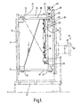
- the weighing apparatus has a rigid support frame mounted on a chassis 10.
- the support frame comprises a first vertical plate 11 from which project two spaced apart upper lugs 12, 13 and one central lower lug 14.
- a central triangular web 15 supports a horizontally extending arm 16.
- a second movable vertical plate 17 is connected to the plate 11 by three flexure arms 18, 19'and 20. These arms extend respectively from the lugs 12, 13 and 14 to similar lugs on the plate 17. Each flexure arm has portions 21 of reduced thickness enabling the arms to flex adjacent to the plates 11 and 17, the remainder of the length of the arms remaining rigid.
- the plates and the flexure arms form a parallelogram type construction, guiding the plate 17 for vertical movement parallel to the plate 11 with a minimum of friction and wear.
- a load cell 22 is connected between the rigid arm 16 and a lug 23 on the plate 17.
- the load cell 22 is connected by means of upper and lower flexure tapes 24 and each tape is connected to the arm 16 or lug 23 by a threaded rod and nut arrangement 25 which enables the position and/or pretension of the load cell 22 to be finely adjusted.
- the degree of vertical movement of the plate 17 is limited by upper and lower adjusting screws 26, 27, fitted into further lugs 28 on the plate 17.
- the downward movement of the plate 17 is limited by engagement of the screw 26 with the upper surface of the arm 16 and the vertical movement of the plate 17 upwardly is limited by engagement of the screw 27 with the underside of the arm 16.
- a spigot 29 Projecting horizontally from the plate 17, away from the load cell 22, in the manner of a cantilever, is a spigot 29 bearing a rectangular flange 30.
- FIG. 3 illustrates the weighing apparatus utilised for automatic weighing.
- a claw 32 which engages over the flange 30 thus transmitting all the load of the weigh pan 31 and any material therein to the plate 17.
- the weigh pan 31 is in the form of a hopper having a pair of lower doors 33 which can be opened by extending a ram 34 and can be closed again by retracting the ram.
- hopper 31 Above the hopper 31 is a filling and metering device 35 which is described in more detail in our co-pending U.K. Patent Application of even date.
- the device 35 is used to fill the hopper 31 and when the weighing apparatus indicates that the hopper 31 has received a predetermined desired quantity of particulate material the metering device 35 is closed to prevent the supply of further material and the doors 33 are opened to release the measured quantity of material. The cycle is then repeated and the weighing may take place very rapidly.
- the construction of the weighing apparatus as shown in Figure 3 is analagous to a person holding a saucepan wherein the pan is the hopper 31, the handle of the saucepan is equivalent to the spigot 29, and the person's wrist supporting and sensing the load is equivalent to the load cell 22.
- the load to be weighed, W (see Figure 1) is applied via the spigot 29 to the plate 17.
- the plate 17 thus moves under the influence of the load W, travelling parallel to the plate 11 under the control of the flexure arms 18, 19 and 20.
- the lug 23 of the plate 17 drops with respect to the arm 16, inducing a tensile load in the load cell 22.
- the electrical signal from the load cell may be transmitted to either a digital or analogue readout device or alternatively may be used for control purposes, for example to control the discharge of material into the hopper.
- the invention has other applications, some of which are illustrated in Figure 4 to 7.
- an apparatus substantially identical to that shown in Figures 1 and 2 has a weigh pan attached thereto in the form of a batch weigher 36. Particulate material is fed continually into the pan 36 and periodically, dependent upon the load in the pan at a given time, a pivotal door 37 is opened to deposit a batch, and is then immediately closed, by means of a ram 38.
- FIG 6 apparatus similar to that shown in Figures 1 and 2 is used to support a platen 41 positioned under a continuous belt 42 used to carry individual packages 43. Asseach package passes over the platen 41 its weight can be checked.
- FIG 7 apparatus similar to that shown in Figures 1 and 2 is is used to support a roller 44 which is positioned between two other support rollers 45 of a continuous belt conveyor 46 carrying material 47.
- the load cell 22 is continually monitoring the weight of material carried by a given length of the belt.
- the weighing apparatus described above with referance to the drawings does not require any anti-sway links or tension wires even for high speed automatic weighing.
- the load is applied cantilever fashion to one side of the apparatus, the loading of the load cell substantially in pure tension enables an accurate reading to be obtained.
- the use of a single cell also means that there is no requirement to match and calibrate a plurality of cells and the capacity of the single cell is increased.
- the single cell has, for example, a working range which is twice that which would be provided by a pair of identical cells.
- the cell Since a simple tension cell may be used, there is no need to use the more expensive shear beam type. Not only can the cell be hermetically sealed but it is, in any event, positioned to one side of the weighing area, out of the immediate vicinity of the particulate material being weighed. It can, if desired, be housed in a separate dustproof compartment.
- the invention is not restricted to the details of the foregoing embodiments. It may be adapted to any type of weighing device, either industrial or domestic, having a single load cell or transducer which carries all the forces from the weighing platform or container.
- the invention can be used to reduce or eliminate the use of springs, levers and the like, normally associated with known weighing machines. It is possible for devices having the features of the invention to meet all the desirable parameters required with other forms of weighing machines or systems.
Landscapes
- Physics & Mathematics (AREA)
- General Physics & Mathematics (AREA)
- Formation And Processing Of Food Products (AREA)
- Feeding, Discharge, Calcimining, Fusing, And Gas-Generation Devices (AREA)
- Confectionery (AREA)
- Weight Measurement For Supplying Or Discharging Of Specified Amounts Of Material (AREA)
- Measurement Of Force In General (AREA)
- Testing Of Balance (AREA)
Priority Applications (1)
| Application Number | Priority Date | Filing Date | Title |
|---|---|---|---|
| AT85307853T ATE46395T1 (de) | 1984-11-08 | 1985-10-30 | Wiegeapparat. |
Applications Claiming Priority (2)
| Application Number | Priority Date | Filing Date | Title |
|---|---|---|---|
| GB8428274A GB2166877B (en) | 1984-11-08 | 1984-11-08 | Weighing apparatus |
| GB8428274 | 1984-11-08 |
Publications (3)
| Publication Number | Publication Date |
|---|---|
| EP0181147A2 true EP0181147A2 (fr) | 1986-05-14 |
| EP0181147A3 EP0181147A3 (en) | 1987-04-01 |
| EP0181147B1 EP0181147B1 (fr) | 1989-09-13 |
Family
ID=10569453
Family Applications (1)
| Application Number | Title | Priority Date | Filing Date |
|---|---|---|---|
| EP85307853A Expired EP0181147B1 (fr) | 1984-11-08 | 1985-10-30 | Dispositif de pesage |
Country Status (4)
| Country | Link |
|---|---|
| EP (1) | EP0181147B1 (fr) |
| AT (1) | ATE46395T1 (fr) |
| DE (1) | DE3573016D1 (fr) |
| GB (1) | GB2166877B (fr) |
Cited By (1)
| Publication number | Priority date | Publication date | Assignee | Title |
|---|---|---|---|---|
| GB2166877B (en) * | 1984-11-08 | 1989-05-17 | Dobson Park Ind | Weighing apparatus |
Family Cites Families (12)
| Publication number | Priority date | Publication date | Assignee | Title |
|---|---|---|---|---|
| FR1491547A (fr) * | 1966-07-01 | 1967-08-11 | Trayvou Sa | Détecteur de charges pour doseuse pondérale automatique |
| US3788411A (en) * | 1972-11-01 | 1974-01-29 | Franklin Elec Subsidiaries | Strainweigh balance |
| US3847238A (en) * | 1973-10-18 | 1974-11-12 | Reliance Electric Co | Weighing scale with restrictive vertical movement |
| DE2622586B2 (de) * | 1976-05-20 | 1978-08-31 | Alkem Gmbh, 6450 Hanau | Wägeeinrichtung |
| GB2086593B (en) * | 1980-10-08 | 1985-02-06 | Davy Instr Ltd | Weighing device |
| CH652209A5 (de) * | 1981-08-18 | 1985-10-31 | Mettler Instrumente Ag | Kraftmesser. |
| JPS5873821A (ja) * | 1981-10-28 | 1983-05-04 | Yamato Scale Co Ltd | ロ−ドセル式はかり |
| CH654412A5 (de) * | 1981-12-22 | 1986-02-14 | Mettler Instrumente Ag | Waage. |
| GB2119527B (en) * | 1982-03-06 | 1985-10-02 | Salter & Co Ltd G | Weighing apparatus |
| EP0093221A1 (fr) * | 1982-05-05 | 1983-11-09 | WIRTH, GALLO & CO | Balance |
| DE3338928C2 (de) * | 1983-10-27 | 1987-03-05 | Messerschmitt-Bölkow-Blohm GmbH, 8012 Ottobrunn | Tag- und Nachtsichtgerät |
| GB2166877B (en) * | 1984-11-08 | 1989-05-17 | Dobson Park Ind | Weighing apparatus |
-
1984
- 1984-11-08 GB GB8428274A patent/GB2166877B/en not_active Expired
-
1985
- 1985-10-30 EP EP85307853A patent/EP0181147B1/fr not_active Expired
- 1985-10-30 AT AT85307853T patent/ATE46395T1/de active
- 1985-10-30 DE DE8585307853T patent/DE3573016D1/de not_active Expired
Cited By (1)
| Publication number | Priority date | Publication date | Assignee | Title |
|---|---|---|---|---|
| GB2166877B (en) * | 1984-11-08 | 1989-05-17 | Dobson Park Ind | Weighing apparatus |
Also Published As
| Publication number | Publication date |
|---|---|
| GB8428274D0 (en) | 1984-12-19 |
| GB2166877B (en) | 1989-05-17 |
| DE3573016D1 (en) | 1989-10-19 |
| EP0181147B1 (fr) | 1989-09-13 |
| ATE46395T1 (de) | 1989-09-15 |
| EP0181147A3 (en) | 1987-04-01 |
| GB2166877A (en) | 1986-05-14 |
Similar Documents
| Publication | Publication Date | Title |
|---|---|---|
| US5065632A (en) | Flow line weighing device | |
| US4463816A (en) | Load cell assembly for conveyor weighing of bulk material | |
| EP2032953A2 (fr) | Système de distribution à équilibrage | |
| US7331210B2 (en) | Conveyor weighbridge with built-in calibration weight | |
| US5834707A (en) | Bulk material scale and flowmeter | |
| JPS61500134A (ja) | ばら材料の流れの流量記録方法及び装置 | |
| US4393950A (en) | Tare weighing apparatus and method therefor | |
| US4407380A (en) | Weighing device for fluent material | |
| AU768576B2 (en) | Chain conveyor | |
| US11754433B2 (en) | Load sensing system with stabilized fulcrums | |
| US4955270A (en) | Dry flow sensor | |
| US4100985A (en) | Vibration-resistant balance | |
| CA1201134A (fr) | Courroie transporteuse-peseuse | |
| EP0181147A2 (fr) | Dispositif de pesage | |
| NL7815061A (nl) | Massa- en krachtmeter. | |
| US4480705A (en) | Platform calibration factor for conveyor inclination angle | |
| US3477533A (en) | Weighing scale mechanism | |
| US4234049A (en) | Mass measuring apparatus | |
| GB2049961A (en) | Apparatus for continuous weighing | |
| EP0020030A1 (fr) | Unité de pesage | |
| US4757867A (en) | Single load cell weighing systems | |
| US20200056931A1 (en) | Calibrating a conveyor and metering device | |
| RU2137096C1 (ru) | Дозатор сыпучих материалов металлургических печей | |
| RU25084U1 (ru) | Весовой дозатор дискретного действия с устройством компенсации веса тары | |
| SU561090A1 (ru) | Конвейерные весы |
Legal Events
| Date | Code | Title | Description |
|---|---|---|---|
| PUAI | Public reference made under article 153(3) epc to a published international application that has entered the european phase |
Free format text: ORIGINAL CODE: 0009012 |
|
| AK | Designated contracting states |
Kind code of ref document: A2 Designated state(s): AT BE CH DE FR GB IT LI LU NL SE |
|
| PUAL | Search report despatched |
Free format text: ORIGINAL CODE: 0009013 |
|
| AK | Designated contracting states |
Kind code of ref document: A3 Designated state(s): AT BE CH DE FR GB IT LI LU NL SE |
|
| 17P | Request for examination filed |
Effective date: 19870910 |
|
| 17Q | First examination report despatched |
Effective date: 19871201 |
|
| GRAA | (expected) grant |
Free format text: ORIGINAL CODE: 0009210 |
|
| AK | Designated contracting states |
Kind code of ref document: B1 Designated state(s): AT BE CH DE FR GB IT LI LU NL SE |
|
| PG25 | Lapsed in a contracting state [announced via postgrant information from national office to epo] |
Ref country code: SE Effective date: 19890913 Ref country code: LI Effective date: 19890913 Ref country code: CH Effective date: 19890913 Ref country code: AT Effective date: 19890913 |
|
| REF | Corresponds to: |
Ref document number: 46395 Country of ref document: AT Date of ref document: 19890915 Kind code of ref document: T |
|
| ITF | It: translation for a ep patent filed | ||
| PGFP | Annual fee paid to national office [announced via postgrant information from national office to epo] |
Ref country code: LU Payment date: 19891018 Year of fee payment: 5 |
|
| REF | Corresponds to: |
Ref document number: 3573016 Country of ref document: DE Date of ref document: 19891019 |
|
| PGFP | Annual fee paid to national office [announced via postgrant information from national office to epo] |
Ref country code: BE Payment date: 19891020 Year of fee payment: 5 |
|
| PGFP | Annual fee paid to national office [announced via postgrant information from national office to epo] |
Ref country code: FR Payment date: 19891026 Year of fee payment: 5 |
|
| ITTA | It: last paid annual fee | ||
| PG25 | Lapsed in a contracting state [announced via postgrant information from national office to epo] |
Ref country code: LU Free format text: LAPSE BECAUSE OF NON-PAYMENT OF DUE FEES Effective date: 19891031 |
|
| PGFP | Annual fee paid to national office [announced via postgrant information from national office to epo] |
Ref country code: NL Payment date: 19891031 Year of fee payment: 5 |
|
| ET | Fr: translation filed | ||
| PGFP | Annual fee paid to national office [announced via postgrant information from national office to epo] |
Ref country code: DE Payment date: 19891214 Year of fee payment: 5 |
|
| REG | Reference to a national code |
Ref country code: CH Ref legal event code: PL |
|
| PLBE | No opposition filed within time limit |
Free format text: ORIGINAL CODE: 0009261 |
|
| STAA | Information on the status of an ep patent application or granted ep patent |
Free format text: STATUS: NO OPPOSITION FILED WITHIN TIME LIMIT |
|
| 26N | No opposition filed | ||
| PGFP | Annual fee paid to national office [announced via postgrant information from national office to epo] |
Ref country code: GB Payment date: 19901025 Year of fee payment: 6 |
|
| PG25 | Lapsed in a contracting state [announced via postgrant information from national office to epo] |
Ref country code: BE Effective date: 19901031 |
|
| BERE | Be: lapsed |
Owner name: DOBSON PARK INDUSTRIES P.L.C. Effective date: 19901031 |
|
| PG25 | Lapsed in a contracting state [announced via postgrant information from national office to epo] |
Ref country code: NL Effective date: 19910501 |
|
| NLV4 | Nl: lapsed or anulled due to non-payment of the annual fee | ||
| PG25 | Lapsed in a contracting state [announced via postgrant information from national office to epo] |
Ref country code: FR Effective date: 19910628 |
|
| PG25 | Lapsed in a contracting state [announced via postgrant information from national office to epo] |
Ref country code: DE Effective date: 19910702 |
|
| REG | Reference to a national code |
Ref country code: FR Ref legal event code: ST |
|
| PG25 | Lapsed in a contracting state [announced via postgrant information from national office to epo] |
Ref country code: GB Effective date: 19911030 |
|
| GBPC | Gb: european patent ceased through non-payment of renewal fee |