EP0181203A2 - Formung von Bauelementen mit komplexem Hohlquerschnitt - Google Patents
Formung von Bauelementen mit komplexem Hohlquerschnitt Download PDFInfo
- Publication number
- EP0181203A2 EP0181203A2 EP85308072A EP85308072A EP0181203A2 EP 0181203 A2 EP0181203 A2 EP 0181203A2 EP 85308072 A EP85308072 A EP 85308072A EP 85308072 A EP85308072 A EP 85308072A EP 0181203 A2 EP0181203 A2 EP 0181203A2
- Authority
- EP
- European Patent Office
- Prior art keywords
- stock
- final
- constriction means
- tubular
- tubular stock
- Prior art date
- Legal status (The legal status is an assumption and is not a legal conclusion. Google has not performed a legal analysis and makes no representation as to the accuracy of the status listed.)
- Withdrawn
Links
Images

Classifications
-
- B—PERFORMING OPERATIONS; TRANSPORTING
- B21—MECHANICAL METAL-WORKING WITHOUT ESSENTIALLY REMOVING MATERIAL; PUNCHING METAL
- B21D—WORKING OR PROCESSING OF SHEET METAL OR METAL TUBES, RODS OR PROFILES WITHOUT ESSENTIALLY REMOVING MATERIAL; PUNCHING METAL
- B21D47/00—Making rigid structural elements or units, e.g. honeycomb structures
- B21D47/01—Making rigid structural elements or units, e.g. honeycomb structures beams or pillars
-
- B—PERFORMING OPERATIONS; TRANSPORTING
- B21—MECHANICAL METAL-WORKING WITHOUT ESSENTIALLY REMOVING MATERIAL; PUNCHING METAL
- B21C—MANUFACTURE OF METAL SHEETS, WIRE, RODS, TUBES, PROFILES OR LIKE SEMI-MANUFACTURED PRODUCTS OTHERWISE THAN BY ROLLING; AUXILIARY OPERATIONS USED IN CONNECTION WITH METAL-WORKING WITHOUT ESSENTIALLY REMOVING MATERIAL
- B21C37/00—Manufacture of metal sheets, rods, wire, tubes, profiles or like semi-manufactured products, not otherwise provided for; Manufacture of tubes of special shape
- B21C37/06—Manufacture of metal sheets, rods, wire, tubes, profiles or like semi-manufactured products, not otherwise provided for; Manufacture of tubes of special shape of tubes or metal hoses; Combined procedures for making tubes, e.g. for making multi-wall tubes
- B21C37/15—Making tubes of special shape; Making tube fittings
- B21C37/151—Making tubes with multiple passages
-
- B—PERFORMING OPERATIONS; TRANSPORTING
- B21—MECHANICAL METAL-WORKING WITHOUT ESSENTIALLY REMOVING MATERIAL; PUNCHING METAL
- B21C—MANUFACTURE OF METAL SHEETS, WIRE, RODS, TUBES, PROFILES OR LIKE SEMI-MANUFACTURED PRODUCTS OTHERWISE THAN BY ROLLING; AUXILIARY OPERATIONS USED IN CONNECTION WITH METAL-WORKING WITHOUT ESSENTIALLY REMOVING MATERIAL
- B21C37/00—Manufacture of metal sheets, rods, wire, tubes, profiles or like semi-manufactured products, not otherwise provided for; Manufacture of tubes of special shape
- B21C37/06—Manufacture of metal sheets, rods, wire, tubes, profiles or like semi-manufactured products, not otherwise provided for; Manufacture of tubes of special shape of tubes or metal hoses; Combined procedures for making tubes, e.g. for making multi-wall tubes
- B21C37/15—Making tubes of special shape; Making tube fittings
- B21C37/155—Making tubes with non-circular section
Definitions
- constriction means comprise a mould with at least one inwardly movable region
- the relative movement is effected by forcing the movable region from a position in which the tubular stock can be introduced into the mould to a final position in which the tubular stock is actively forced to adopt a final configuration
- constriction means comprise a die having an aperture therethrough of cross-sectional shape changing from a shape into which the stock can be introduced to a final desired shape
- the relative movement is effected by forcing the stock through the die whereby the stock is actively forced to adopt the final desired shape
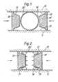
- a moulding tool comprises spaced upper and lower members 10, 11 having facing surfaces 12, 13 respectively. In between these surfaces are provided side members 14, 15 each having facing surfaces 16, 17 respectively. Urging means, not shown, are provided to urge the side members 14, 15 inwards towards each other in a controlled manner.
- the surfaces 12, 13 and 16, 17 form the interior of the mould and are thus shaped to form the final configuration of an article to be moulded when the side members are in the fully inward position.
- a section 20 of tubular stock of superplastically deformable material is sealed at both ends and filled with an inert gas. It is placed in the mould when the side menbers 14, 15 are in the outward position.
- the section is conveniently of circular form, but other shapes can be utilised with effect.
- the side members 14, 15 When heated to within the temperature range at which superplastic deformation can take place, the side members 14, 15 are urged inwards to contact and gradually deform the tubular stock.
- the gaseous pressure within the section of tubular stock causes the material thereof to be urged against the interior of the mould as illustrated in Figure 2.
- the gaseous pressure is either the result of charging the section with a pressurised gas initally, or the residual pressure generated by the constriction effect of the mould side portions. Naturally it can also be a combination of both.
- Figure 3 shows a final configuration where the side members 14, 15 are moved to their most inward position.
- two opposed surfaces 16 -, 17- urge two regions of the circular sectioned stock (which regions were originally diametrically opposite of one another) together to form a double layered web of a generally I-sectioned beam.
- diffusion bonding can be effected at this region by causing the side members 14, 15 to be sufficiently strongly urged to produce the necessary bonding pressure.
- the final article is an I-sectioned beam with hollow flanges at the top and bottom joined by a double layered diffusion banded web.
- a similar mould tool to that of the previous figures is provided, but is modified to have regions formed in the surfaces 12, 13 of the upper and lower members to accommodate capping members, 21, 22.
- These capping members are of diffusion bondable material so that when the material of the cylindrical stock 20 is urged against them under a suitable pressure exerted by the pressure within the stock section under the action of the urgeable side memembers 14, 15 diffusion bonding at regions 23, 24 takes place.
- a reinforced I-section article can be formed.
- the above methods and apparatus can be used to form constant or varying sectioned articles.
Landscapes
- Engineering & Computer Science (AREA)
- Mechanical Engineering (AREA)
- Shaping Metal By Deep-Drawing, Or The Like (AREA)
Applications Claiming Priority (2)
| Application Number | Priority Date | Filing Date | Title |
|---|---|---|---|
| GB8428064 | 1984-11-06 | ||
| GB848428064A GB8428064D0 (en) | 1984-11-06 | 1984-11-06 | Forming complex hollow sectioned members |
Publications (2)
| Publication Number | Publication Date |
|---|---|
| EP0181203A2 true EP0181203A2 (de) | 1986-05-14 |
| EP0181203A3 EP0181203A3 (de) | 1987-01-21 |
Family
ID=10569338
Family Applications (1)
| Application Number | Title | Priority Date | Filing Date |
|---|---|---|---|
| EP85308072A Withdrawn EP0181203A3 (de) | 1984-11-06 | 1985-11-06 | Formung von Bauelementen mit komplexem Hohlquerschnitt |
Country Status (2)
| Country | Link |
|---|---|
| EP (1) | EP0181203A3 (de) |
| GB (1) | GB8428064D0 (de) |
Cited By (11)
| Publication number | Priority date | Publication date | Assignee | Title |
|---|---|---|---|---|
| US4989774A (en) * | 1988-08-17 | 1991-02-05 | British Aerospace Public Limited Company | Structural box beams |
| FR2691088A1 (fr) * | 1990-11-28 | 1993-11-19 | Arbault Jean | Procédé d'assemblage de tubes ronds par aplatissement partiel. |
| WO2002076652A1 (en) * | 2001-03-23 | 2002-10-03 | Volvo Lastvagnar Ab | Hollow construction element and method of producing |
| EP2273069A3 (de) * | 2009-07-02 | 2011-10-12 | Rolls-Royce plc | Verfahren zum Bilden einer inneren Struktur in einer Hohlkomponente |
| US8182233B2 (en) | 2007-07-13 | 2012-05-22 | Rolls-Royce Plc | Component with a damping filler |
| US8241004B2 (en) | 2008-05-15 | 2012-08-14 | Rolls-Royce, Plc | Component structure |
| US8365388B2 (en) | 2009-01-28 | 2013-02-05 | Rolls-Royce Plc | Method of joining plates of material to form a structure |
| US8529720B2 (en) | 2008-07-24 | 2013-09-10 | Rolls-Royce, Plc | Aerofoil sub-assembly, an aerofoil and a method of making an aerofoil |
| US8701286B2 (en) | 2010-06-02 | 2014-04-22 | Rolls-Royce Plc | Rotationally balancing a rotating part |
| US8920893B2 (en) | 2009-01-27 | 2014-12-30 | Rolls-Royce Plc | Article with an internal structure |
| US8986490B2 (en) | 2010-11-26 | 2015-03-24 | Rolls-Royce Plc | Method of manufacturing a component |
Family Cites Families (3)
| Publication number | Priority date | Publication date | Assignee | Title |
|---|---|---|---|---|
| US2055771A (en) * | 1933-04-18 | 1936-09-29 | Aluminum Co Of America | Method of making shafts |
| GB1415510A (en) * | 1972-08-15 | 1975-11-26 | British Aircraft Corp Ltd | Forming of metals |
| DE2941972A1 (de) * | 1979-10-17 | 1981-04-30 | Thyssen Industrie Ag, 4300 Essen | Verfahren zur herstellung von hohlen metallkoerpern |
-
1984
- 1984-11-06 GB GB848428064A patent/GB8428064D0/en active Pending
-
1985
- 1985-11-06 EP EP85308072A patent/EP0181203A3/de not_active Withdrawn
Cited By (14)
| Publication number | Priority date | Publication date | Assignee | Title |
|---|---|---|---|---|
| US4989774A (en) * | 1988-08-17 | 1991-02-05 | British Aerospace Public Limited Company | Structural box beams |
| FR2691088A1 (fr) * | 1990-11-28 | 1993-11-19 | Arbault Jean | Procédé d'assemblage de tubes ronds par aplatissement partiel. |
| WO2002076652A1 (en) * | 2001-03-23 | 2002-10-03 | Volvo Lastvagnar Ab | Hollow construction element and method of producing |
| US7721443B2 (en) | 2001-03-23 | 2010-05-25 | International Rectifier Corporation | Method for producing a vehicle axle |
| US8381398B2 (en) | 2007-07-13 | 2013-02-26 | Rolls-Royce Plc | Component with a damping filler and method |
| US8857054B2 (en) | 2007-07-13 | 2014-10-14 | Rolls-Royce Plc | Method of forming an aerofoil with a damping filler |
| US8182233B2 (en) | 2007-07-13 | 2012-05-22 | Rolls-Royce Plc | Component with a damping filler |
| US8241004B2 (en) | 2008-05-15 | 2012-08-14 | Rolls-Royce, Plc | Component structure |
| US8529720B2 (en) | 2008-07-24 | 2013-09-10 | Rolls-Royce, Plc | Aerofoil sub-assembly, an aerofoil and a method of making an aerofoil |
| US8920893B2 (en) | 2009-01-27 | 2014-12-30 | Rolls-Royce Plc | Article with an internal structure |
| US8365388B2 (en) | 2009-01-28 | 2013-02-05 | Rolls-Royce Plc | Method of joining plates of material to form a structure |
| EP2273069A3 (de) * | 2009-07-02 | 2011-10-12 | Rolls-Royce plc | Verfahren zum Bilden einer inneren Struktur in einer Hohlkomponente |
| US8701286B2 (en) | 2010-06-02 | 2014-04-22 | Rolls-Royce Plc | Rotationally balancing a rotating part |
| US8986490B2 (en) | 2010-11-26 | 2015-03-24 | Rolls-Royce Plc | Method of manufacturing a component |
Also Published As
| Publication number | Publication date |
|---|---|
| EP0181203A3 (de) | 1987-01-21 |
| GB8428064D0 (en) | 1984-12-12 |
Similar Documents
| Publication | Publication Date | Title |
|---|---|---|
| US5214948A (en) | Forming metal parts using superplastic metal alloys and axial compression | |
| KR100517584B1 (ko) | 하이드로폼 성형된 각진 관형 부품 및 이를 제조하기 위한방법 및 장치 | |
| EP0181203A2 (de) | Formung von Bauelementen mit komplexem Hohlquerschnitt | |
| EP0294034B1 (de) | Verfahren zum Herstellen kistenförmiger Gegenstände | |
| CA2445582C (en) | Method of pressure-ram-forming metal containers and the like | |
| US6216509B1 (en) | Hydroformed tubular member and method of hydroforming tubular members | |
| US4829803A (en) | Method of forming box-like frame members | |
| CA2104826A1 (en) | Apparatus and method for forming and hydropiercing a tubular frame member | |
| US4833768A (en) | Curved SPF/DB sandwich fabrication | |
| JPH0255127B2 (de) | ||
| US4364252A (en) | Method for the manufacture of diaphragm bellows | |
| US4509671A (en) | Method of producing diffusion bonded superplastically formed structures | |
| US2929109A (en) | Method for molding pulverulent material | |
| US20040194522A1 (en) | Method of pressure-ram-forming metal containers and the like | |
| RU2118219C1 (ru) | Способ штамповки-вытяжки изделий из листового металла | |
| EP0079622A2 (de) | Vorrichtung zum Zusammenfügen von Behälterhälften | |
| WO1994020234A1 (en) | Method of forming tubular members | |
| JPH0311852B2 (de) | ||
| KR100352788B1 (ko) | 판재를 사용하여 플랜지를 갖는 부재의 하이드로포밍방법 | |
| EP0081883A2 (de) | Verfahren und Vorrichtung zum Anformen einer Muffe an ein Rohr aus thermoplastischem Kunststoff | |
| JPS56134037A (en) | Closed forging method, forming die device, and closed forging press for annular body | |
| JPH0532143B2 (de) | ||
| SU1219207A1 (ru) | Устройство дл формообразовани полых изделий | |
| US3474649A (en) | Progressive deformation method and means using tubular blanks | |
| SU1209357A1 (ru) | Устройство дл деформировани заготовок |
Legal Events
| Date | Code | Title | Description |
|---|---|---|---|
| PUAI | Public reference made under article 153(3) epc to a published international application that has entered the european phase |
Free format text: ORIGINAL CODE: 0009012 |
|
| 17P | Request for examination filed |
Effective date: 19860110 |
|
| AK | Designated contracting states |
Kind code of ref document: A2 Designated state(s): DE FR GB |
|
| PUAL | Search report despatched |
Free format text: ORIGINAL CODE: 0009013 |
|
| AK | Designated contracting states |
Kind code of ref document: A3 Designated state(s): DE FR GB |
|
| STAA | Information on the status of an ep patent application or granted ep patent |
Free format text: STATUS: THE APPLICATION HAS BEEN WITHDRAWN |
|
| 18W | Application withdrawn |
Withdrawal date: 19870721 |
|
| RIN1 | Information on inventor provided before grant (corrected) |
Inventor name: STEPHEN, DAVIDBRITISH AEROSPACE P.L.C. Inventor name: MANSBRIDGE, MARTIN HENRYBRITISH AEROSPACE P.L.C. |