EP0181263B1 - Kopfzusammenbau mit schmaler Kontur - Google Patents
Kopfzusammenbau mit schmaler Kontur Download PDFInfo
- Publication number
- EP0181263B1 EP0181263B1 EP85402123A EP85402123A EP0181263B1 EP 0181263 B1 EP0181263 B1 EP 0181263B1 EP 85402123 A EP85402123 A EP 85402123A EP 85402123 A EP85402123 A EP 85402123A EP 0181263 B1 EP0181263 B1 EP 0181263B1
- Authority
- EP
- European Patent Office
- Prior art keywords
- island
- tape
- head assembly
- top surface
- guide
- Prior art date
- Legal status (The legal status is an assumption and is not a legal conclusion. Google has not performed a legal analysis and makes no representation as to the accuracy of the status listed.)
- Expired - Lifetime
Links
- 239000000356 contaminant Substances 0.000 description 6
- 238000011109 contamination Methods 0.000 description 5
- 239000000463 material Substances 0.000 description 5
- 238000004140 cleaning Methods 0.000 description 4
- 230000035699 permeability Effects 0.000 description 4
- 238000010586 diagram Methods 0.000 description 3
- 230000000694 effects Effects 0.000 description 3
- 230000009471 action Effects 0.000 description 2
- 230000000712 assembly Effects 0.000 description 2
- 238000000429 assembly Methods 0.000 description 2
- 239000000919 ceramic Substances 0.000 description 2
- 230000009467 reduction Effects 0.000 description 2
- VYZAMTAEIAYCRO-UHFFFAOYSA-N Chromium Chemical compound [Cr] VYZAMTAEIAYCRO-UHFFFAOYSA-N 0.000 description 1
- 229910010293 ceramic material Inorganic materials 0.000 description 1
- 230000005684 electric field Effects 0.000 description 1
- 230000004907 flux Effects 0.000 description 1
- 230000003993 interaction Effects 0.000 description 1
- 238000003754 machining Methods 0.000 description 1
- 238000000034 method Methods 0.000 description 1
- 238000005498 polishing Methods 0.000 description 1
- 230000005855 radiation Effects 0.000 description 1
- 238000000926 separation method Methods 0.000 description 1
- 230000007704 transition Effects 0.000 description 1
Images

Classifications
-
- G—PHYSICS
- G11—INFORMATION STORAGE
- G11B—INFORMATION STORAGE BASED ON RELATIVE MOVEMENT BETWEEN RECORD CARRIER AND TRANSDUCER
- G11B5/00—Recording by magnetisation or demagnetisation of a record carrier; Reproducing by magnetic means; Record carriers therefor
- G11B5/127—Structure or manufacture of heads, e.g. inductive
-
- G—PHYSICS
- G11—INFORMATION STORAGE
- G11B—INFORMATION STORAGE BASED ON RELATIVE MOVEMENT BETWEEN RECORD CARRIER AND TRANSDUCER
- G11B23/00—Record carriers not specific to the method of recording or reproducing; Accessories, e.g. containers, specially adapted for co-operation with the recording or reproducing apparatus ; Intermediate mediums; Apparatus or processes specially adapted for their manufacture
- G11B23/50—Reconditioning of record carriers; Cleaning of record carriers ; Carrying-off electrostatic charges
- G11B23/502—Reconditioning of record carriers; Cleaning of record carriers ; Carrying-off electrostatic charges of tape carriers
-
- G—PHYSICS
- G11—INFORMATION STORAGE
- G11B—INFORMATION STORAGE BASED ON RELATIVE MOVEMENT BETWEEN RECORD CARRIER AND TRANSDUCER
- G11B5/00—Recording by magnetisation or demagnetisation of a record carrier; Reproducing by magnetic means; Record carriers therefor
- G11B5/127—Structure or manufacture of heads, e.g. inductive
- G11B5/187—Structure or manufacture of the surface of the head in physical contact with, or immediately adjacent to the recording medium; Pole pieces; Gap features
- G11B5/1871—Shaping or contouring of the transducing or guiding surface
-
- G—PHYSICS
- G11—INFORMATION STORAGE
- G11B—INFORMATION STORAGE BASED ON RELATIVE MOVEMENT BETWEEN RECORD CARRIER AND TRANSDUCER
- G11B23/00—Record carriers not specific to the method of recording or reproducing; Accessories, e.g. containers, specially adapted for co-operation with the recording or reproducing apparatus ; Intermediate mediums; Apparatus or processes specially adapted for their manufacture
- G11B23/50—Reconditioning of record carriers; Cleaning of record carriers ; Carrying-off electrostatic charges
Definitions
- This invention relates to a head structure for a digital magnetic recording assembly.
- the basic head assembly for a digital magnetic recording device such as a reel-to-reel tape, consists of an approximately U-shaped core made from some high permeability material, with a small non-magnetic gap at the top and an electric coil wound around the base of the core.
- the tape or other magnetic media moves across the gap at a predetermined distance, usually on the order of 10 ⁇ 4-10 ⁇ 5 inches (2,540 10 ⁇ 6m - 2,540 10 ⁇ 7m) above it.
- a time-varying electric current is sent through the coil to produce a time-varying magnetic field in the core.
- the magnetic flux lines bridge the non-magnetic gap and create a fringe field above it, which in turn lays down a spatially varying magnetic pattern on the tape.
- the magnetic pattern on the tape induces a time-varying magnetic field in the core and an associated current in the coil.
- Wide island heads do provide a reliable aerodynamic cushion.
- the cushion alone does not ensure good contact for the life of the recording assembly.
- Relatively high pressures are required to provide contact on the wide, flat surface of the head, so the entire head wears quickly, and the soft core wears much more quickly than the sliders.
- the distance between tape and core increases so the signals lose resolution and the noise on the tape increases. This leads to signal losses on the recording tracks and, even worse, synchronization failures on the timing track which can turn the entire tape to gibberish.
- the sliders must be ground down, a complex and expensive procedure which involves taking apart, reassembling and recalibrating the entire tape player. Since cores cannot be replaced onsite, the tape player must be "down" for several weeks per year while the cores are being replaced.
- the invention provides a head assembly for a magnetic tape drive according to appended claim 1.
- FIG 1 is a cross-sectional diagram of a paired head assembly for a flexible tape drive embodying the invention.
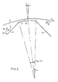
- FIG 2 is a detail diagram of island, 20, from FIG 1, more specifically showing its contour and orientation.
- FIG 3 is a detail diagram of island, showing the machined and final head contours, and indicating the effects of wrap angle and island width on head pressure.
- a paired head assembly for a magnetic tape drive is shown in cross-section in Figure 1.
- a paired head assembly a given section of the tape is first written by the write head and immediately thereafter checked by the read head.
- a tape, 10 is drawn over the surfaces of the write and read heads, generally designated by the numerals 20 and 30 respectively, and of outrigger bumps, 40 and 50, whose function will be discussed later.
- the tape path is horizontal. Because it is difficult to precisely control the tension of a horizontal tape, most designers cause the tape to climb uphill at a slight angle over the write head and then to pass downhill at a slight angle over the read head. Prior art designers have, however, attempted to make this transition as gradual as possible and to maintain the tape to head surface spacing nearly constant over the entire head assembly by the use of wide, smooth sliders mounted flush with the heads.
- the head island of my invention features a convex raised top surface and sloping sides; in cross-section it roughly resembles the frustum of a cone.
- the heads are made from a high permeability material, preferably a ceramic.
- the top surface, 21, of the write head is broken by a write gap, 22.
- the top surface, 31, of the read head is broken by a read gap, 32, through which the magnetic pattern on the tape intereacts with the field surrounding the head core.
- the sides, 23, and 24, of write head 20 are sloped at angles ⁇ and ( ⁇ w + ⁇ ) respectively so that the angle of approach between the tape, 10, and each side of the head is ⁇ .
- the read head be designed so that all angles are equal in magnitude (though opposite in sign) to those for the write head.
- the sides, 33 and 34 of read head 30 are sloped at angles ⁇ + ⁇ w ' and ⁇ ' respectively so that the angle of approach between the tape, 10, and each side of the head is ⁇ '.
- ⁇ should be at least about 10°.
- my assembly deliberately creates reduced tape to head spacing and large pressure gradients at the edges of the top surface of the head. In effect, the air cushion and any contaminants which may have been picked up by a given section of tape are scraped off just before that section passes over the head gap. The tape is thus self-cleaning.
- ⁇ is between 10° and 15°.
- the sharp corners of the head can act like small antennae, emitting radiation and creating false signals known as contour pulses on the tape.
- the tape to head spacing is not uniform across the width of the tape, and this disparity becomes more marked, as ⁇ increases beyond about 15°.
- the structural integrity of the ceramic material suffers and machining, polishing and or tape interaction with sharp edges may cause chipping or fracturing of these edges.
- top width of my island and the wrap angle ⁇ w for my heads are chosen to provide control over the flutter in the tape as it passes over the head and also over the pressure exerted on the head. It should be noted in passing that for a head radius of curvature greater than the natural radius, the wrap angle equals the angle included by the top surface of the head, and this is approximately true when the radius is slightly less than the natural radius.
- My invention features an island which is narrower by a factor of at least 3 than prior art wide islands.
- the width of the island need not be greater than 150/D, where D is the storage density of the tape in bits per inch (2,54 cm).
- D is the storage density of the tape in bits per inch (2,54 cm).
- the pressure on the head be not less than about 6 psi (4,1376 N/cm2), and because unduly high pressures increase wear on both tape and head, it is preferred that the pressure not exceed 10 psi (6,896 N/cm2).
- the wrap angle ⁇ w is a fine-tuning device to balance the island width and psi (N/cm2) loading; angles in a range of about 5° to about 10° are preferred.
- the final radius of curvature of the head approximates the "natural radius of curvature R w " of the tape.
- N being an inherent property of the tape
- T is also constrained by external factors such as the power of the drive motors and the tensile strength of the tape itself, and, as I have mentioned, it is desirable that T be kept as small as is consistent with maintaining contact between the tape and the magnetic field. It has been found that heads with a machined radius substantially shorter than the natural radius have erratic recording behavior early in the head life due to lift off of the tape from the head. The head will wear down rapidly and, because of lift-off, irregularly, creating a large volume of debris which tends to stick to the tape causing high error rates.
- the head may never attain a smooth steady-state radius, but may continue to have a significant wear rate throughout the head life.
- Heads whose machined radii are substantially longer than the natural radius of curvature of the tape also have been found to wear irregularly.
- heads with an initial machined radius of curvature no less than about half the natural radius have been found to wear in rapidly without much lift-off to a contour approximating the natural curvature of the tape, and to have negligible wear thereafter.
- the machined radius be from 1/2 to 2/3 of the natural radius of curvature of the tape.
- a head with an initial surface, 21, at an initial radius of curvature, Ro is shown. If the natural radius of curvature, R w , of the tape, 10, is slightly more than R o , it will be seen that the head will tend to wear down to a final surface, 21', with a radius of curvature equal to R w .
- the vertical head loss to wear, and hence the possible contamination due to debris, is proportional to the difference between the inverses of the initial and final radii and also proportional to the square of the island width. H w ⁇ (1/2R o -1/2R w ) ⁇ W 2 /4
- the narrow contour island of my invention greatly reduces the likelihood of contamination from weardown debris.
- the steep slope of the head provides a "trap" into which the debris can fall so that it does not adhere to the tape.
- the tape, 10, passes over outrigger islands, 40 and 50, on either side of the head islands 20 and 30.
- These outrigger islands are made from a low permeability material of substantially the same hardness as the head material, such as low permeability ceramic.
- the outrigger islands are preferably substantially identical in size and contour to the head islands. They provide an additional cleaning action for the tape.
- the wrap around the "extra" island is also functionally equivalent to doubling the wrap angle at the head, providing improved tension and flutter control without the wear at the tape edges which a single large wrap angle would cause.
- the head assembly of my invention features one or more steeply sloped, raised head islands approached by the tape at an angle greater than about 10° and wrapped by the tape at an angle between about 5° and 10°. It also features a narrow convex top surface whose radius of curvature approximates the natural curvature of the tape. It has been shown that these features work together to provide the unique advantages described.
- the steeply sloped head contour, the constraints on the machined head radius, and the narrow top width minimize contamination during the initial weardown of the head to its running radius while the choice of radius ensures that the weardown phase is short and wear thereafter minimal.
- the sloping head contour by an air tunnel effect cleans the tape and provides a trap for debris.
- the small island size reduces errors caused by contamination.
- the small island size, the choice of included, i.e., wrap angle, and a running radius which approximates the natural radius of curvature minimize wear on the tape.
Landscapes
- Engineering & Computer Science (AREA)
- Manufacturing & Machinery (AREA)
- Magnetic Heads (AREA)
Claims (3)
- Kopfzusammenbau für einen Magnetbandantrieb mit einer Transporteinrichtung zum Transport des Magnetbands (10) entlang einer Bandtransportbahn, welches Band einen natürlichen Krümmungsradius (Rw) aufweist, wobei ein Teil der Bandtransportbahn in unmittelbarer Nähe des Kopfzusammenbaus verläuft, damit durch den Kopfzusammenbau Daten auf dem Band ausgelesen oder eingeschrieben werden können, und wobei(A) der Kopfzusammenbau eine im wesentlichen bogenförmige äußere Oberfläche aufweist, angrenzend an die der Teil der Bandtransportbahn verläuft,(B) eine Schreibinsel (20) einstückig mit dem Kopfzusammenbau ausgebildet ist und über die äußere Oberfläche des Kopfzusammenbaus vorragt, welche Schreibinsel (20) eine bogenförmig gewölbte Oberfläche in einem Abstand von der äußeren Oberfläche des Kopfzusammenbaus aufweist, und(C) eine Leseinsel (30) einstückig mit dem Kopfzusammenbau ausgebildet ist und über die äußere Oberfläche des Kopfzusammenbaus vorragt, sowie einen Abstand von der Schreibinsel (20) aufweist, derart daß ein bogenförmig gewölbter Teil der bogenförmigen äußeren Oberfläche des Kopfzusammenbaus dazwischen vorhanden ist, welche Leseinsel (30) eine bogenförmige obere Oberfläche in einem Abstand von der äußeren Oberfläche des Kopfzusammenbaus aufweist, dadurch gekennzeichnet, daß die obere Oberfläche der Schreibinsel einen Krümmungsradius (Ro) aufweist, der im wesentlichen gleich dem natürlichen Krümmungsradius (Rw) des Bands (10) ist, sowie Schreibinselseiten (23,24) aufweist, die sich zwiwchen der äußeren Oberfläche des Kopfzusammenbaus und der oberen Oberfläche der Schreibinsel erstrecken, welche Schreibinselseiten eben ausgebildet sind und sich nach unten von einer Linie, die durch die Endpunkte der oberen Oberfläche der Schreibinsel definiert ist, um mindestens 10° erstrecken, und daß die obere Oberfläche der Leseinsel einen Krümmungsradius (Ro) aufweist, der im wesentlichen gleich dem natürlichen Krümmungsradius (Rw) des Bands (10) ist, sowie Leseinselseiten (33,34) aufweist, die sich zwischen der äußeren Oberfläche des Kopfzusammenbaus und der oberen Oberfläche der Leseinsel erstrecken, welche Leseinselseiten eben ausgebildet sind und sich nach unten von einer Linie, die durch die Endstellen der oberen Oberfläche der Leseinsel definiert ist, um mindestens 10° erstrecken.
- Kopfzusammenbau nach Anspruch 1, dadurch gekennzeichnet, daß(A) eine erste Führungsinsel (40) einstückig mit der äußeren Oberfläche des Kopfzusammenbaus ausgebildet ist und sich davon über diesen erstrecken, welche erste Führungsinsel (40) einen Abstand von der Schreibinsel (20) entgegengesetzt zu der Richtung aufweist, wo die Leseinsel (30) vorgesehen ist, welche erste Führungsinsel eine erste bogenförmige obere Oberfläche in einem Abstand von der äußeren Oberfläche des Kopfzusammenbaus aufweist, welche obere Oberfläche der ersten Führungsinsel einen Krümmungsradius aufweist, der im wesentlichen gleich dem natürlichen Krümmungsradius des Bands ist, sowie Seiten der ersten Führungsinsel, die sich zwischen der äußeren Oberfläche des Kopfzusammenbaus und der ersten oberen Oberfläche der Führungsinsel erstreckt, welche Seiten der ersten Führungsinsel eben ausgebildet sind und sich nach unten um mindestens 10° von einer Linie erstrecken, die durch die Endpunkte der oberen Oberfläche der ersten Führungsinsel definiert ist, und daß(B) eine zweite Führungsinsel (50) einstückig mit der äußeren Oberfläche des Kopfzusammenbaus ausgebildet ist und sich über diesen erstreckt, welche zweite Führungsinsel (50) einen Abstand von der Leseinsel (30) entgegengesetzt zu der Richtung aufweist, wo die Schreibinsel (20) vorgesehen ist, welche zweite Führungsinsel eine bogenförmige obere Oberfläche in einem Abstand von der äußeren Oberfläche des Kopfzusammenbaus aufweist, welche zweite obere Oberfläche der Führungsinsel einen Krümmungsradius aufweist, der im wesentlichen gleich dem natürlichen Krümmungsradius des Bands ist, sowie Seiten der zweiten Führungsinsel aufweist, die sich zwischen der äußeren Oberfläche des Kopfzusammenbaus und der oberen Oberfläche der zweiten Führungsinsel erstrecken, welche Seiten der zweiten Führungsinsel eben ausgebildet sind und sich nach unten um mindestens 10° von einer Linie erstrecken, die durch die Endstellen der oberen Oberfläche der zweiten Führungsinsel definiert ist.
- Kopfzusammenbau nach Anspruch 2, dadurch gekennzeichnet, daß die obere Oberfläche (21) der Schreibinsel (20), die obere Oberfläche (31) der Leseinsel (30), die obere Oberfläche der ersten Führungsinsel (40) und die obere Oberfläche der zweiten Führungsinsel (50) jeweils einem Winkel zwischen 5° und 10° einschließlich gegenüberliegen.
Applications Claiming Priority (2)
| Application Number | Priority Date | Filing Date | Title |
|---|---|---|---|
| US66941084A | 1984-11-08 | 1984-11-08 | |
| US669410 | 1984-11-08 |
Publications (3)
| Publication Number | Publication Date |
|---|---|
| EP0181263A2 EP0181263A2 (de) | 1986-05-14 |
| EP0181263A3 EP0181263A3 (en) | 1988-07-20 |
| EP0181263B1 true EP0181263B1 (de) | 1992-01-29 |
Family
ID=24686236
Family Applications (1)
| Application Number | Title | Priority Date | Filing Date |
|---|---|---|---|
| EP85402123A Expired - Lifetime EP0181263B1 (de) | 1984-11-08 | 1985-11-05 | Kopfzusammenbau mit schmaler Kontur |
Country Status (8)
| Country | Link |
|---|---|
| US (1) | US4809110A (de) |
| EP (1) | EP0181263B1 (de) |
| JP (1) | JPH0754570B2 (de) |
| KR (1) | KR940003645B1 (de) |
| AU (1) | AU583066B2 (de) |
| CA (1) | CA1247736A (de) |
| DE (1) | DE3585310D1 (de) |
| IE (1) | IE57499B1 (de) |
Families Citing this family (34)
| Publication number | Priority date | Publication date | Assignee | Title |
|---|---|---|---|---|
| EP0397713B1 (de) * | 1987-12-28 | 1994-06-01 | Eastman Kodak Company | PROFILIERTE KOPFVORRICHTUNG FüR KASSETTENSPIELER |
| WO1989006421A1 (en) * | 1987-12-28 | 1989-07-13 | Eastman Kodak Company | Magnetic head with constant area wear profile |
| US4868697A (en) * | 1987-12-28 | 1989-09-19 | Eastman Kodak Company | Magnetic head with constant area wear profile |
| EP0373179B1 (de) * | 1987-12-28 | 1993-10-27 | Eastman Kodak Company | In einem kassettentonbandgerät verwendeter koplanarer magnetischer kopfzusammenbau |
| JPH0298806A (ja) * | 1988-10-06 | 1990-04-11 | Canon Inc | マルチトラック薄膜磁気ヘッド |
| US4949724A (en) * | 1988-12-23 | 1990-08-21 | Mahutte Cornelis K | Method and apparatus for continuous measurement of cardiac output |
| US4956737A (en) * | 1989-04-04 | 1990-09-11 | Eastman Kodak Company | Magnetic head contour utilizing facets for air film skiving |
| US5055959A (en) * | 1990-01-09 | 1991-10-08 | Digital Equipment Corporation | Tape head with low spacing loss produced by narrow and wide wear regions |
| US5034838A (en) * | 1990-05-08 | 1991-07-23 | Eastman Kodak Company | Bi-directional read while write magnetic head assembly having a wear avoidance contour |
| US5214553A (en) * | 1991-04-29 | 1993-05-25 | Digital Equipment Corporation | Magnetic contact recording head for operation with tapes of varying thicknesses |
| DE4220860A1 (de) * | 1992-06-25 | 1994-01-05 | Basf Ag | Vorrichtung zur Oberflächenbearbeitung von Materialbahnen |
| TW235361B (de) * | 1992-11-13 | 1994-12-01 | Philips Electronics Nv | |
| US5426551A (en) * | 1993-07-19 | 1995-06-20 | Quantum Corp. | Magnetic contact head having a composite wear surface |
| US5423116A (en) * | 1993-07-21 | 1995-06-13 | Storage Technology Corporation | Method of manufacturing a multi-track longitudinal, metal-in-gap head |
| US5394285A (en) * | 1993-07-21 | 1995-02-28 | Storage Technology Corporation | Multi-track longitudinal, metal-in-gap head |
| JPH0997406A (ja) * | 1995-04-27 | 1997-04-08 | Eastman Kodak Co | 空気を掻き取るための傾斜したスロットを横方向に有する磁気ヘッド組立体 |
| US5844814A (en) * | 1996-09-27 | 1998-12-01 | International Business Machines Corporation | Optical position sensing device and method for sub-micron measurement |
| US5969912A (en) * | 1997-12-10 | 1999-10-19 | Cope; James Robert | Bidirectional magnetic read/write recording head surface contour with plurality of Bernoulli Pocket cavities for generating very low media-to-head separations |
| US7179551B2 (en) | 1999-02-12 | 2007-02-20 | General Electric Company | Poly(arylene ether) data storage media |
| KR100755089B1 (ko) | 1999-02-12 | 2007-09-03 | 제너럴 일렉트릭 캄파니 | 저장 매체, 기판 제조 방법, 데이터 검색 방법, 엠보싱 방법 및 데이터 저장 매체 형성 방법 |
| JP3551099B2 (ja) * | 1999-09-28 | 2004-08-04 | 日本電気株式会社 | 磁気テープ装置用薄膜磁気ヘッド |
| US6690542B1 (en) | 2000-12-13 | 2004-02-10 | Seagate Removable Storage Solutions Llc | Dual module RWW tape head assembly |
| US20020155216A1 (en) * | 2001-04-19 | 2002-10-24 | Reitz John Bradford | Spin coated media |
| US7050264B2 (en) * | 2002-11-15 | 2006-05-23 | Imation Corp. | Linear magnetic tape head with tape contact area projected minimal height above non-rotating contoured head surface |
| US7271983B2 (en) * | 2004-09-16 | 2007-09-18 | Quantum Corporation | Magnetic head with mini-outriggers and method of manufacture |
| US7256963B2 (en) * | 2004-09-16 | 2007-08-14 | Quantum Corporation | Magnetic head with adaptive data island and mini-outrigger and methods of manufacture |
| US7369362B2 (en) | 2005-03-16 | 2008-05-06 | Quantum Corporation | Tape cleaning apparatus |
| US20060227459A1 (en) * | 2005-04-11 | 2006-10-12 | Quantum Corporation | Integrated tape and data transducer head cleaning device |
| US20070183091A1 (en) * | 2006-02-03 | 2007-08-09 | Saliba George A | Read/write head having varying wear regions and methods of manufacture |
| US8958175B1 (en) | 2014-01-16 | 2015-02-17 | Oracle International Corporation | Tape head surface with non-uniform cross-width profile |
| US9928855B1 (en) | 2016-10-31 | 2018-03-27 | International Business Machines Corporation | Tape head and system having asymmetrical construction |
| US9837104B1 (en) | 2016-10-31 | 2017-12-05 | International Business Machines Corporation | Tape head having sensors proximate to an edge |
| US10068591B2 (en) | 2016-12-05 | 2018-09-04 | International Business Machines Corporation | Head having wrap-controlled flexible media interface |
| US10418059B2 (en) | 2016-12-06 | 2019-09-17 | International Business Machines Corporation | Methods for selecting wrap angle for inducing tape tenting above transducer |
Family Cites Families (10)
| Publication number | Priority date | Publication date | Assignee | Title |
|---|---|---|---|---|
| US3573769A (en) * | 1967-10-30 | 1971-04-06 | Gen Electric | Magnetic head with air relief slots |
| US3806902A (en) * | 1972-05-15 | 1974-04-23 | Nortronics Co | Magnetic head read-to-write gap crossfeed shielding |
| JPS5189408A (de) * | 1975-02-03 | 1976-08-05 | ||
| US3947887A (en) * | 1975-04-03 | 1976-03-30 | Storage Technology Corporation | Transducer head contour and method of generating same |
| JPS5321065U (de) * | 1976-07-29 | 1978-02-22 | ||
| JPS5534490A (en) * | 1978-09-01 | 1980-03-11 | Canon Inc | Alignment device |
| JPS562127U (de) * | 1979-06-14 | 1981-01-09 | ||
| NL8100143A (nl) * | 1981-01-14 | 1982-08-02 | Philips Nv | Inrichting voor magnetische opname en weergave van signalen en magnetische overdrachtskop daarvoor. |
| US4479158A (en) * | 1982-05-12 | 1984-10-23 | International Business Machines Corporation | Stationary magnetic head with a fluid operated tape lifter |
| KR100208134B1 (ko) * | 1997-06-25 | 1999-07-15 | 최진호 | 진공청소기의 흡입장치 |
-
1985
- 1985-11-05 DE DE8585402123T patent/DE3585310D1/de not_active Expired - Fee Related
- 1985-11-05 EP EP85402123A patent/EP0181263B1/de not_active Expired - Lifetime
- 1985-11-07 AU AU49423/85A patent/AU583066B2/en not_active Ceased
- 1985-11-07 KR KR1019850008316A patent/KR940003645B1/ko not_active Expired - Fee Related
- 1985-11-07 IE IE2779/85A patent/IE57499B1/en not_active IP Right Cessation
- 1985-11-07 CA CA000494766A patent/CA1247736A/en not_active Expired
- 1985-11-08 JP JP60250572A patent/JPH0754570B2/ja not_active Expired - Fee Related
-
1987
- 1987-10-08 US US07/106,935 patent/US4809110A/en not_active Expired - Lifetime
Also Published As
| Publication number | Publication date |
|---|---|
| IE852779L (en) | 1986-05-08 |
| KR940003645B1 (ko) | 1994-04-25 |
| IE57499B1 (en) | 1993-02-24 |
| JPH0754570B2 (ja) | 1995-06-07 |
| AU583066B2 (en) | 1989-04-20 |
| EP0181263A3 (en) | 1988-07-20 |
| DE3585310D1 (de) | 1992-03-12 |
| CA1247736A (en) | 1988-12-28 |
| EP0181263A2 (de) | 1986-05-14 |
| AU4942385A (en) | 1986-05-29 |
| US4809110A (en) | 1989-02-28 |
| JPS61115208A (ja) | 1986-06-02 |
| KR860004389A (ko) | 1986-06-20 |
Similar Documents
| Publication | Publication Date | Title |
|---|---|---|
| US4809110A (en) | Narrow contour head assembly | |
| US5905613A (en) | Bidirectional flat contour linear tape recording head and drive | |
| US5296993A (en) | Magnetic head with magnetic substrate and an enhanced poletip thereon | |
| US4130847A (en) | Corrosion resistant thin film head assembly and method for making | |
| EP0482170B1 (de) | In zwei richtungen, lesenden während schreibenden, magnetkopfzusammenbau mit abnützung vermeidender kontur | |
| US8542460B2 (en) | Head for tape drive with transversely varying contour | |
| US5055959A (en) | Tape head with low spacing loss produced by narrow and wide wear regions | |
| US5963401A (en) | Magnetic tape head assembly including modules having a plurality of magneto-resistive head elements | |
| US4888657A (en) | Contoured head assembly for use in a cassette loaded recorder | |
| EP1477967A2 (de) | Bandkopf mit dünner Trägerflache und Herstellungsverfahren | |
| US20160210993A1 (en) | Tape media kiss-contact read verification | |
| US5220473A (en) | Multitrack magnetic head assembly having a tape-engaging surface contoured for continuous in-contact recording | |
| US5978176A (en) | Magnetic head for a magnetic disk having a slider with indented portions for providing heat dissipation | |
| EP0340882B1 (de) | Dünnschichtmagnetkopf | |
| US6614621B2 (en) | Method of making thin film magnetic head having upper auxillary magnetic pole of accurately set thickness | |
| US5555145A (en) | Floating head slider with a magnetic head integrated therein | |
| US20040141255A1 (en) | Magnetic head device and recording/reproducing apparatus using the same | |
| EP0627732A1 (de) | Dünnfilmwandler mit reduzierter Flughöhe | |
| EP0511755B1 (de) | Kontakt-Aufnahmemagnetkopf für den Betrieb mit Bändern unterschiedlicher Dicke | |
| US6989961B2 (en) | Magnetic head with medium sliding surface having varied curvature and recording/reproducing apparatus | |
| JPS62270015A (ja) | 浮上型磁気ヘツド | |
| EP0460702B1 (de) | Magnetkopf | |
| US20040070871A1 (en) | Magnetic head assembly and magnetic tape drive unit and magnetic disk drive unit using magnetic head assembly | |
| KR19990077803A (ko) | 회전 드럼 장치 및 자기 기록/재생장치 | |
| EP0124435B1 (de) | Dünnfilmmagnetkopf mit Abnützungsanzeige |
Legal Events
| Date | Code | Title | Description |
|---|---|---|---|
| PUAI | Public reference made under article 153(3) epc to a published international application that has entered the european phase |
Free format text: ORIGINAL CODE: 0009012 |
|
| AK | Designated contracting states |
Kind code of ref document: A2 Designated state(s): DE FR GB IT NL SE |
|
| PUAL | Search report despatched |
Free format text: ORIGINAL CODE: 0009013 |
|
| AK | Designated contracting states |
Kind code of ref document: A3 Designated state(s): DE FR GB IT NL SE |
|
| 17P | Request for examination filed |
Effective date: 19881227 |
|
| 17Q | First examination report despatched |
Effective date: 19900912 |
|
| GRAA | (expected) grant |
Free format text: ORIGINAL CODE: 0009210 |
|
| AK | Designated contracting states |
Kind code of ref document: B1 Designated state(s): DE FR GB IT NL SE |
|
| REF | Corresponds to: |
Ref document number: 3585310 Country of ref document: DE Date of ref document: 19920312 |
|
| ITF | It: translation for a ep patent filed | ||
| ET | Fr: translation filed | ||
| ITTA | It: last paid annual fee | ||
| PLBE | No opposition filed within time limit |
Free format text: ORIGINAL CODE: 0009261 |
|
| STAA | Information on the status of an ep patent application or granted ep patent |
Free format text: STATUS: NO OPPOSITION FILED WITHIN TIME LIMIT |
|
| 26N | No opposition filed | ||
| EAL | Se: european patent in force in sweden |
Ref document number: 85402123.5 |
|
| PGFP | Annual fee paid to national office [announced via postgrant information from national office to epo] |
Ref country code: FR Payment date: 19981020 Year of fee payment: 14 |
|
| PGFP | Annual fee paid to national office [announced via postgrant information from national office to epo] |
Ref country code: SE Payment date: 19981021 Year of fee payment: 14 |
|
| PGFP | Annual fee paid to national office [announced via postgrant information from national office to epo] |
Ref country code: NL Payment date: 19981026 Year of fee payment: 14 |
|
| PGFP | Annual fee paid to national office [announced via postgrant information from national office to epo] |
Ref country code: GB Payment date: 19991020 Year of fee payment: 15 Ref country code: DE Payment date: 19991020 Year of fee payment: 15 |
|
| PG25 | Lapsed in a contracting state [announced via postgrant information from national office to epo] |
Ref country code: SE Free format text: LAPSE BECAUSE OF NON-PAYMENT OF DUE FEES Effective date: 19991106 |
|
| PG25 | Lapsed in a contracting state [announced via postgrant information from national office to epo] |
Ref country code: NL Free format text: LAPSE BECAUSE OF NON-PAYMENT OF DUE FEES Effective date: 20000601 |
|
| EUG | Se: european patent has lapsed |
Ref document number: 85402123.5 |
|
| PG25 | Lapsed in a contracting state [announced via postgrant information from national office to epo] |
Ref country code: FR Free format text: LAPSE BECAUSE OF NON-PAYMENT OF DUE FEES Effective date: 20000731 |
|
| NLV4 | Nl: lapsed or anulled due to non-payment of the annual fee |
Effective date: 20000601 |
|
| REG | Reference to a national code |
Ref country code: GB Ref legal event code: 732E |
|
| REG | Reference to a national code |
Ref country code: FR Ref legal event code: ST |
|
| PG25 | Lapsed in a contracting state [announced via postgrant information from national office to epo] |
Ref country code: GB Free format text: LAPSE BECAUSE OF NON-PAYMENT OF DUE FEES Effective date: 20001105 |
|
| GBPC | Gb: european patent ceased through non-payment of renewal fee |
Effective date: 20001105 |
|
| PG25 | Lapsed in a contracting state [announced via postgrant information from national office to epo] |
Ref country code: DE Free format text: LAPSE BECAUSE OF NON-PAYMENT OF DUE FEES Effective date: 20010801 |