EP0181271A1 - Kunststoffschraubkappe für den Sicherheitsverschluss einer Tube und der Gebrauch dieser Kappe - Google Patents
Kunststoffschraubkappe für den Sicherheitsverschluss einer Tube und der Gebrauch dieser Kappe Download PDFInfo
- Publication number
- EP0181271A1 EP0181271A1 EP85420172A EP85420172A EP0181271A1 EP 0181271 A1 EP0181271 A1 EP 0181271A1 EP 85420172 A EP85420172 A EP 85420172A EP 85420172 A EP85420172 A EP 85420172A EP 0181271 A1 EP0181271 A1 EP 0181271A1
- Authority
- EP
- European Patent Office
- Prior art keywords
- tube
- capsule
- bar
- opening
- shoulder
- Prior art date
- Legal status (The legal status is an assumption and is not a legal conclusion. Google has not performed a legal analysis and makes no representation as to the accuracy of the status listed.)
- Granted
Links
- 239000004033 plastic Substances 0.000 title claims abstract description 7
- 229920003023 plastic Polymers 0.000 title claims abstract description 7
- 238000007789 sealing Methods 0.000 claims abstract description 4
- 239000002775 capsule Substances 0.000 claims description 77
- 238000003466 welding Methods 0.000 claims description 20
- 230000002093 peripheral effect Effects 0.000 claims description 3
- 238000002604 ultrasonography Methods 0.000 claims description 2
- 239000000463 material Substances 0.000 abstract description 3
- -1 polypropylene Polymers 0.000 description 5
- 239000004743 Polypropylene Substances 0.000 description 4
- 229920001155 polypropylene Polymers 0.000 description 4
- 229960005486 vaccine Drugs 0.000 description 4
- 238000004806 packaging method and process Methods 0.000 description 3
- 238000000926 separation method Methods 0.000 description 3
- 238000010008 shearing Methods 0.000 description 2
- 239000007787 solid Substances 0.000 description 2
- 239000004698 Polyethylene Substances 0.000 description 1
- 230000015572 biosynthetic process Effects 0.000 description 1
- 238000004040 coloring Methods 0.000 description 1
- 238000005520 cutting process Methods 0.000 description 1
- 230000000694 effects Effects 0.000 description 1
- 239000003889 eye drop Substances 0.000 description 1
- 229940012356 eye drops Drugs 0.000 description 1
- 239000003292 glue Substances 0.000 description 1
- 238000004519 manufacturing process Methods 0.000 description 1
- 238000005259 measurement Methods 0.000 description 1
- 238000012986 modification Methods 0.000 description 1
- 230000004048 modification Effects 0.000 description 1
- 238000000465 moulding Methods 0.000 description 1
- 239000000825 pharmaceutical preparation Substances 0.000 description 1
- 229940127557 pharmaceutical product Drugs 0.000 description 1
- 229920000573 polyethylene Polymers 0.000 description 1
- 238000007790 scraping Methods 0.000 description 1
- 230000001954 sterilising effect Effects 0.000 description 1
- 238000004659 sterilization and disinfection Methods 0.000 description 1
Images

Classifications
-
- B—PERFORMING OPERATIONS; TRANSPORTING
- B65—CONVEYING; PACKING; STORING; HANDLING THIN OR FILAMENTARY MATERIAL
- B65D—CONTAINERS FOR STORAGE OR TRANSPORT OF ARTICLES OR MATERIALS, e.g. BAGS, BARRELS, BOTTLES, BOXES, CANS, CARTONS, CRATES, DRUMS, JARS, TANKS, HOPPERS, FORWARDING CONTAINERS; ACCESSORIES, CLOSURES, OR FITTINGS THEREFOR; PACKAGING ELEMENTS; PACKAGES
- B65D41/00—Caps, e.g. crown caps or crown seals, i.e. members having parts arranged for engagement with the external periphery of a neck or wall defining a pouring opening or discharge aperture; Protective cap-like covers for closure members, e.g. decorative covers of metal foil or paper
- B65D41/32—Caps or cap-like covers with lines of weakness, tearing-strips, tags, or like opening or removal devices, e.g. to facilitate formation of pouring openings
- B65D41/34—Threaded or like caps or cap-like covers provided with tamper elements formed in, or attached to, the closure skirt
- B65D41/3495—Threaded or like caps or cap-like covers provided with tamper elements formed in, or attached to, the closure skirt the tamper element being bonded or adhered to the container wall
Definitions
- the invention relates to a screw closure cap, made of plastic, with an improved tamper-evident system. It relates to the technical field of packaging elements.
- Patent application EP 0049 876 thus describes a screw cap whose tamper-evident band is connected to the lower part of the skirt by breakable bridges, this tamper-evident band comprising tabs the end of which abuts under the counter of the container during the closing screwing. The opening then produces the separation of the tamper-evident band separation which makes obvious pre opening for a user or consumer notified of the pre - initial presentation of the package.
- tamper-evident systems with a tear-off strip may also be used, but the mere tearing of a tamper-evident strip is not a sign of sufficient prior opening to safely attract the attention of all those who may need to use these doses of vaccine in different countries and countries.
- the tube to which the invention applies has a shoulder connected to the body of the tube and surmounted by an end cannula carrying at its base an external thread, while the capsule of the invention comprises, as is known, a cap carrying an internal thread which can be screwed onto the external thread of the tube cannula, as well as, at its lower part, a collar inclined typically like the shoulder of the tube.
- the lower surface of the collar is then, for example, frustoconical, with an angle at the top of the corresponding cone of the order of 120 * .
- the screwing of the capsule on the tube produces a tight closure produced in the usual way by the application and the wedging of the conical surface of the interior of the cap of the capsule on the external conical surface of the end cannula. tube, or better made using a flexible peripheral lip carried by the interior of the cap of the capsule at the level of the cannula of the tube.
- the flange of the capsule of the invention comprises at least one opening extending up to the periphery of said flange, and at least one tamper-evident strip located at the level and, in general, housed in said opening, this strip being connected to the capsule by at least one connecting bridge.
- This bar is preferably connected to the capsule by two connecting bridges, a longitudinal bridge which connects the front end of the bar to the edge of the collar delimiting the front of its "opening of the collar, and a transverse bridge connecting the internal longitudinal edge of the bar at the longitudinal edge of the flange delimiting this same opening
- This bar further carries, under its underside and near its rear end in the direction of unscrewing the capsule, a relief bearing only punctually, by one or possibly by several very small contact surfaces, on the shoulder of the tube after screwing on the capsule.
- the collar comprises, on the edge delimiting the rear of the opening described above, an oblique face inclined downwards depending on the direction of unscrewing the capsule.
- the tamper-evident closure of the tube is obtained by screwing the capsule, the latter coming through the relief from the underside of its collar abutting "punctually" on the shoulder of the tube, then by welding leading to the formation of at least one welding point, with crushing of this relief, from its point of contact or stop.
- This local welding is typically carried out by ultrasound, with an adjustment such that, when unscrewing the capsule, the connecting bridges break before this welding point.
- the complete detachment of the bar is then obtained by the start of the free rotation of the capsule, the oblique face of the edge delimiting the rear of the opening of the collar lifting and pushing the rear end of the bar by breaking its welding point.
- the punctual bearing of the relief of the underside of the bar on the shoulder is prepared in various ways: for example, by using a raised pin, or by using a transverse rib whose lower edge is inclined, the height of the rib increasing from the inside to the outside of the bar. From the point of view of the ease of molding and the mode of rupture of the bar, it is advantageous to use such a transverse rib situated in the extension of the transverse connecting bridge.
- the ruptures are then typically at the beginning of the unscrewing of the capsule: rupture by traction of the longitudinal connecting bridge, then rupture by shearing of the transverse connecting bridge, then slight rotation of the capsule and rupture of the welding point thanks to the action of the oblique face of the edge delimiting the rear of the opening of the collar.
- An opening of the collar of the capsule according to the invention is usually 0.1 times to 0.4 times the length of the periphery of the collar. It is possible to use 2 or 3 openings spaced around the periphery of the collar and 2 or 3 bars associated with each of its openings, these openings and bars can be of different geometries. To limit the maximum breaking torque required, it is then preferable to offset the positions of the inclined oblique faces situated on the edges delimiting the rear of the various openings so that, when the capsule closing the tube is opened, the breaks weld points of the bars are made successively.
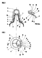
- the capsule (1) of the first example ( Figures 1 and 2) includes, as is known in the prior art, a cap (2) carrying three gripping ribs (3), a slightly inclined flange (4) and inside from its cap (2) a thread (5) screwable onto the external thread (6) of the cannula (7) of the tube (8).
- the flange (4) has an opening (9) extending over its entire width and about 20% of the length of its periphery, and a strip (10) connected to the capsule (1) by two connecting bridges (11 , 12): a longitudinal bridge (11) which connects the front end (13) of the bar (10) to the edge (14) of the flange (4) delimiting the front of its opening (9), and a bridge transverse (12) which connects the longitudinal edge (16) of the collar (4) delimiting this same opening (9).
- These two bridges (11, 12) fix the position of the bar (10) during transport and sufficiently for the closure of the tube (8) by the capsule (1) by screwing the capsule (1) and welding the bar (10).
- the flange (4) has substantially the same inclination as the shoulder (17) of the tube (8).
- the bar (10) carries under its underside a rib (18), here in the extension of its transverse connecting bridge (12), and the lower edge (19) of this rib is inclined, the height of the rib ( 18) increasing by going towards the outside of the bar (10), so that, after screwing on the capsule (1) on the tube (8) (FIG. 2), the bar (10) bears on the shoulder ( 17) of the tube (8) by a point-like or almost point-like contact surface (20) (FIG. 2a) close to the rear edge (21) of the bar (10) (FIG. 2a).
- front and rear of the present description refer by convention to the direction of rotation of the capsule during its unscrewing, direction represented by the arrow (22) in each of Figures 1, 3a, 3b, 3c and 4 .
- the collar (4) of the capsule (1) also has, in addition to the opening (9) and the tamper-evident bar (10) thus connected to the capsule (1) by two connecting bridges (11, 12) and provided with a relief (18) ensuring its punctual bearing on the shoulder (17) of the tube (8) when screwing the cap (1) to the bottom of this tube, an oblique face (23) located on the edge (24) delimiting the rear of the opening (9) and inclined downward in the direction (22) of unscrewing the capsule.
- This oblique face (23) is such that, once the connecting bridges (11, 12) broken by the unscrewing force and the capsule (1) then rotating relative to the tube (8) while the bar (10) remains fixed due to the presence of the welding point (200) which connects it to the shoulder (17) of the tube (8) (FIG. 3c), it makes it possible to lift the rear edge (21) of the bar (10) and to break the welding point (200) by tearing or by shearing, the bar (10) being then completely detached from the container and the unscrewing of the capsule (1) becoming free.
- the oblique transverse face (23) thus plays the role of a bevelled blade scraping the surface of the shoulder (17) of the tube (8) and inserting by its free edge (25) under the rear edge (21) of the bar (10), which is raised here from 0.3 to 0.5 mm from the shoulder (17) of the tube (8) by the welding point (200).
- the oblivious face that (23) makes an optimal angle of 30 to 35 ° with the direction of the axis. of the capsule, and it has been determined that generally this angle should preferably be between 25 and 40 °.
- FIGS. 3a to 3c represent a partial section at the location of the bar, sectioning the longitudinal connecting bridge (11) as well as the rib (18) of the bar (10) in the region of its punctual contact (20).
- the representations are limited to the cutting surface BB.
- 3a corresponds to the non-screwed cap, there is seen from left to right in section the edge (24) delimiting the rear of the opening (9) of the flange (4) and forming the oblique face (23), then the bar (10) carrying under its lower face (26) the rib (18) whose lower edge (19) carries the "point" contact point (20) close to the rear edge (21) of the bar (10 ), then the bridge (11) connecting the bar (10) with the edge (14) of the collar located at the front of its opening (9).
- the lateral faces (27, 28) of the rib (18) defining its lower edge (19) form between them an angle here equal to approximately 60 °, and the maximum height of the rib (18) corresponding to the level of the point (20 ) relative to the underside (26) of the bar (10) is 0.7 mm.
- the angle between the faces (27, 28) is preferably between 50 and 70 °, this at least in the region of the maximum relief point or contact point (20), and the maximum height of the rib (18) relative to the lower face (26) is preferably between 0.5 and 1 mm, so as to obtain a satisfactory welding point (200).
- This weld point (200) must be more solid than each of the connecting bridges (11, 12) for the stress of unscrewing, and not too solid so as to be broken without excessive effort by the means already described of the oblique face ( 23), which according to this section makes an optimal angle of 30 to 35 ° with the direction X of the axis of the capsule (1).
- Figure 3b shows the same elements as Figure 3a, for the screwed position on the tube. While the flange (4) is applied correctly on the shoulder (17) of the tube (8), or very close to this shoulder (17), on either side of its opening (9), the bar (10 ) is raised with a maximum spacing relative to the shoulder (17) of the tube (8) in its rear outer zone, close to the contact point (20). Thanks to its attachment to the capsule (1) by the two connecting bridges (11, 12) and to this contact point (20), the bar (10) is firmly applied to the shoulder (17) of the tube (8).
- Figure 3c is placed after welding of the bar (10), the tube being closed by the capsule in a tamper-proof manner.
- the weld point (200) was formed by means of a conventional ultrasonic welding head applied to the strip (10). In this welding, the rib (18) is crushed, so that the height of the welded point (200) fixing at this point the spacing of the bar (10) and the shoulder (17) of the tube is About 0.4 mm.
- the height of the welded connection (200) corresponding to a preferred maximum rib height of between 0.5 and 1 mm is typically between 0.2 and 0.6 mm.
- Such heights correspond to a choice of ultrasonic welding conditions easily performed by a person skilled in the art.
- the spacing thus produced between the bar (10) and the shoulder (17) of the tube (8) will allow the action of the oblique face (23), action which has already been described.
- the interior of the cap (2) of the capsule (1) carries, at the level of the cannula (7) of the tube (8) a peripheral sealing lip (29) directed towards the bottom forming a fold of the inner surface of the cap (2).
- the flexibility of this lip (29) makes it possible to absorb the deformations due to a sterilization treatment of the closed tube without loss of tightness.
- a capsule corresponding to the first example is described below with regard to its characteristics according to the invention, with reference to the same figures.
- It is a polypropylene capsule for closing a small vaccine dose tube, polypropylene tube.
- the capsule has a total height of 22 mm, an internal diameter of 5 mm at the level of its thread (5), and at the bottom of its cap (2) carrying three gripping ribs (3), a flange (4) inclined by 30 ° approximately on the horizontal with an outside diameter of 12 mm and a thickness of 1.2 mm.
- the width of the lower face of the collar (4) is 3 mm, that of its upper face is 2.5 mm, and the collar has an opening (9) extending over this entire width of 2.5 mm and over a curvilinear length of approximately 8 mm, corresponding to an angle of approximately 70 °, that is to say still approximately 22% of the length of the periphery of the collar (4).
- the bar (10) is identical to a portion of the collar (4), it has a width of 1.5 mm and is 2.5 mm shorter than the opening (9). It is connected to the capsule (1) by a longitudinal bridge (11), the outside of which is in line with the periphery of the collar (4) and the external longitudinal edge of the bar (10), 1.5 mm long. and of cross section approximately 0.35 x 0.35 mm, and by a transverse bridge (12) of length 1 mm and of cross section approximately 0.35 x 0.35 mm situated in the extension of a fine rib carried by the underside (26) of the bar (10) 1.5 mm from the rear edge (21) of the bar.
- a longitudinal bridge (11) the outside of which is in line with the periphery of the collar (4) and the external longitudinal edge of the bar (10), 1.5 mm long. and of cross section approximately 0.35 x 0.35 mm, and by a transverse bridge (12) of length 1 mm and of cross section approximately 0.35 x 0.35 mm situated in the extension of a fine rib carried
- the body of the bar (10) is thus 1 mm from the curved longitudinal edge of the flange (4) which delimits the opening (9), and respectively 1.5 mm from the edge (14) and 1 mm from the end (25) of the edge (24) which delimit the opening (9).
- the rib (18) has a maximum height of 0.7 mm with a lower edge (19) inclined so as to bear only "punctually" on the shoulder (17) of the tube (8).
- the edge (24) delimiting the rear of the opening (9) is chamfered over its entire thickness, this chamfer forming an oblique face (23) making an angle of 30 ° with the direction of the axis of the capsule. and headed down.
- a sample of tube closed by this capsule is easily opened, this opening producing the separation of the tamper-evident strip.
- the opening or hollow of the collar is very apparent, and its contrast is increased by coloring of the capsule.
- FIG. 4 shows the use of the tamper evident device in triplicate on the same capsule (100).
- the three bars (10, 10 ', 10 ") have identical geometries and connecting bridges and ribs.
- the corresponding openings (9, 9', 9") are spaced apart along the circumference of the flange (4 ).
- the respective spacings between the rear ends (21, 21 ', 21 ") of the bars (10,10', 10") and the edges (24, 24 ', 24 ") delimiting the rear of the openings (9, 9' , 9 ") go from 1 to 1.5 mm increasing from one bar to another.
- the capsule of the invention most often adapts to tubes with a diameter between 10 and 50 mm, and its collar then has a thickness between 1 and 1.5 mm and a diameter between 10 and 50 mm.
- the collar generally has a minimum width of 2 mm and the bar (s) have a minimum width of 1 mm.
- the capsule is typically either polypropylene or polyethylene, it is usually polypropylene in the case of a tube for pharmaceutical use.
- the tube associated with the capsule is also typically made from one of the two preceding materials.
- inventions of the inventive capsule include the packaging of vaccines, eye drops and other pharmaceutical products, as well as various industrial products such as glues.
Landscapes
- Engineering & Computer Science (AREA)
- Mechanical Engineering (AREA)
- Closures For Containers (AREA)
- Materials For Medical Uses (AREA)
- Tubes (AREA)
- Thiazole And Isothizaole Compounds (AREA)
- Compositions Of Macromolecular Compounds (AREA)
- Laminated Bodies (AREA)
- Processing And Handling Of Plastics And Other Materials For Molding In General (AREA)
- Infusion, Injection, And Reservoir Apparatuses (AREA)
- Plural Heterocyclic Compounds (AREA)
Priority Applications (1)
| Application Number | Priority Date | Filing Date | Title |
|---|---|---|---|
| AT85420172T ATE34356T1 (de) | 1984-10-03 | 1985-10-01 | Kunststoffschraubkappe fuer den sicherheitsverschluss einer tube und der gebrauch dieser kappe. |
Applications Claiming Priority (2)
| Application Number | Priority Date | Filing Date | Title |
|---|---|---|---|
| FR8415348A FR2571026B1 (fr) | 1984-10-03 | 1984-10-03 | Capsule a vis en matiere plastique pour la fermeture inviolable d'un tube et utilisation de ladite capsule |
| FR8415348 | 1984-10-03 |
Publications (2)
| Publication Number | Publication Date |
|---|---|
| EP0181271A1 true EP0181271A1 (de) | 1986-05-14 |
| EP0181271B1 EP0181271B1 (de) | 1988-05-18 |
Family
ID=9308401
Family Applications (1)
| Application Number | Title | Priority Date | Filing Date |
|---|---|---|---|
| EP85420172A Expired EP0181271B1 (de) | 1984-10-03 | 1985-10-01 | Kunststoffschraubkappe für den Sicherheitsverschluss einer Tube und der Gebrauch dieser Kappe |
Country Status (10)
| Country | Link |
|---|---|
| EP (1) | EP0181271B1 (de) |
| AT (1) | ATE34356T1 (de) |
| DE (1) | DE3562744D1 (de) |
| DK (1) | DK162157C (de) |
| ES (1) | ES296014Y (de) |
| FI (1) | FI79503C (de) |
| FR (1) | FR2571026B1 (de) |
| GR (1) | GR852396B (de) |
| NO (1) | NO166701C (de) |
| PT (1) | PT81237B (de) |
Cited By (10)
| Publication number | Priority date | Publication date | Assignee | Title |
|---|---|---|---|---|
| GB2242678A (en) * | 1990-04-04 | 1991-10-09 | Gene Stull | Non-resealable dispenser cap assembly |
| EP0780316A1 (de) * | 1995-12-22 | 1997-06-25 | Virbac S.A. | Manipulierbarer Behälter aus Kunststoff |
| FR2742733A1 (fr) * | 1995-12-22 | 1997-06-27 | Virbac Sa | Recipient manipulable en matiere plastique |
| WO2006092077A1 (de) * | 2005-03-03 | 2006-09-08 | Hoffmann Neopac Ag | Verschlusskappe |
| JP2010280430A (ja) * | 2009-06-08 | 2010-12-16 | Japan Crown Cork Co Ltd | 合成樹脂製蓋及びかかる蓋と容器本体とから構成された容器 |
| JP2010285162A (ja) * | 2009-06-09 | 2010-12-24 | Japan Crown Cork Co Ltd | 合成樹脂製蓋と容器本体とから構成された容器 |
| JP2010285163A (ja) * | 2009-06-09 | 2010-12-24 | Japan Crown Cork Co Ltd | 合成樹脂製蓋及びかかる蓋と容器本体とから構成された容器 |
| JP2010285160A (ja) * | 2009-06-09 | 2010-12-24 | Japan Crown Cork Co Ltd | 合成樹脂製蓋及びかかる蓋と容器本体とから構成された容器 |
| JP2010285161A (ja) * | 2009-06-09 | 2010-12-24 | Japan Crown Cork Co Ltd | 蓋装着方法 |
| JP2011063294A (ja) * | 2009-09-17 | 2011-03-31 | Japan Crown Cork Co Ltd | 合成樹脂製蓋及びかかる蓋と容器本体とから構成された容器 |
Families Citing this family (1)
| Publication number | Priority date | Publication date | Assignee | Title |
|---|---|---|---|---|
| DE4125987A1 (de) * | 1991-08-06 | 1993-02-18 | Henkel Kgaa | Schraubkappe fuer flasche mit dosierspitze |
Citations (4)
| Publication number | Priority date | Publication date | Assignee | Title |
|---|---|---|---|---|
| US3731849A (en) * | 1971-07-23 | 1973-05-08 | Teledyne Mid America Corp | Container and cap combination to indicate tampering |
| FR2276238A1 (fr) * | 1974-06-28 | 1976-01-23 | Bouchage Mecanique | Capsule inviolable a crans |
| US4098419A (en) * | 1977-02-18 | 1978-07-04 | Maxcap Inc. | Blow molded plastic bottle and antitamper cap |
| DE3025903A1 (de) * | 1980-05-28 | 1981-12-03 | Angelo Guala S.p.A., Alessandria | Garantie-verschluss fuer flaschen |
-
1984
- 1984-10-03 FR FR8415348A patent/FR2571026B1/fr not_active Expired
-
1985
- 1985-09-30 DK DK441485A patent/DK162157C/da not_active IP Right Cessation
- 1985-10-01 EP EP85420172A patent/EP0181271B1/de not_active Expired
- 1985-10-01 AT AT85420172T patent/ATE34356T1/de not_active IP Right Cessation
- 1985-10-01 DE DE8585420172T patent/DE3562744D1/de not_active Expired
- 1985-10-02 ES ES1985296014U patent/ES296014Y/es not_active Expired
- 1985-10-02 PT PT81237A patent/PT81237B/pt not_active IP Right Cessation
- 1985-10-02 NO NO853903A patent/NO166701C/no unknown
- 1985-10-02 FI FI853810A patent/FI79503C/fi not_active IP Right Cessation
- 1985-10-03 GR GR852396A patent/GR852396B/el unknown
Patent Citations (4)
| Publication number | Priority date | Publication date | Assignee | Title |
|---|---|---|---|---|
| US3731849A (en) * | 1971-07-23 | 1973-05-08 | Teledyne Mid America Corp | Container and cap combination to indicate tampering |
| FR2276238A1 (fr) * | 1974-06-28 | 1976-01-23 | Bouchage Mecanique | Capsule inviolable a crans |
| US4098419A (en) * | 1977-02-18 | 1978-07-04 | Maxcap Inc. | Blow molded plastic bottle and antitamper cap |
| DE3025903A1 (de) * | 1980-05-28 | 1981-12-03 | Angelo Guala S.p.A., Alessandria | Garantie-verschluss fuer flaschen |
Cited By (12)
| Publication number | Priority date | Publication date | Assignee | Title |
|---|---|---|---|---|
| GB2242678A (en) * | 1990-04-04 | 1991-10-09 | Gene Stull | Non-resealable dispenser cap assembly |
| GB2242678B (en) * | 1990-04-04 | 1994-02-02 | Gene Stull | Non-resealable dispenser cap construction |
| EP0780316A1 (de) * | 1995-12-22 | 1997-06-25 | Virbac S.A. | Manipulierbarer Behälter aus Kunststoff |
| FR2742733A1 (fr) * | 1995-12-22 | 1997-06-27 | Virbac Sa | Recipient manipulable en matiere plastique |
| FR2742734A1 (fr) * | 1995-12-22 | 1997-06-27 | Virbac Sa | Perfectionnement a un recipient manipulable en matiere plastique |
| WO2006092077A1 (de) * | 2005-03-03 | 2006-09-08 | Hoffmann Neopac Ag | Verschlusskappe |
| JP2010280430A (ja) * | 2009-06-08 | 2010-12-16 | Japan Crown Cork Co Ltd | 合成樹脂製蓋及びかかる蓋と容器本体とから構成された容器 |
| JP2010285162A (ja) * | 2009-06-09 | 2010-12-24 | Japan Crown Cork Co Ltd | 合成樹脂製蓋と容器本体とから構成された容器 |
| JP2010285163A (ja) * | 2009-06-09 | 2010-12-24 | Japan Crown Cork Co Ltd | 合成樹脂製蓋及びかかる蓋と容器本体とから構成された容器 |
| JP2010285160A (ja) * | 2009-06-09 | 2010-12-24 | Japan Crown Cork Co Ltd | 合成樹脂製蓋及びかかる蓋と容器本体とから構成された容器 |
| JP2010285161A (ja) * | 2009-06-09 | 2010-12-24 | Japan Crown Cork Co Ltd | 蓋装着方法 |
| JP2011063294A (ja) * | 2009-09-17 | 2011-03-31 | Japan Crown Cork Co Ltd | 合成樹脂製蓋及びかかる蓋と容器本体とから構成された容器 |
Also Published As
| Publication number | Publication date |
|---|---|
| FR2571026A1 (fr) | 1986-04-04 |
| DK162157B (da) | 1991-09-23 |
| EP0181271B1 (de) | 1988-05-18 |
| ES296014U (es) | 1987-07-16 |
| PT81237B (pt) | 1988-12-15 |
| ATE34356T1 (de) | 1988-06-15 |
| DK441485D0 (da) | 1985-09-30 |
| FI853810A0 (fi) | 1985-10-02 |
| ES296014Y (es) | 1988-01-16 |
| FR2571026B1 (fr) | 1986-12-12 |
| DE3562744D1 (en) | 1988-06-23 |
| GR852396B (de) | 1986-01-17 |
| FI79503C (fi) | 1990-01-10 |
| PT81237A (fr) | 1985-11-01 |
| NO166701B (no) | 1991-05-21 |
| FI79503B (fi) | 1989-09-29 |
| DK162157C (da) | 1992-02-24 |
| NO853903L (no) | 1986-04-04 |
| FI853810L (fi) | 1986-04-04 |
| NO166701C (no) | 1991-08-28 |
| DK441485A (da) | 1986-04-04 |
Similar Documents
| Publication | Publication Date | Title |
|---|---|---|
| EP0270134B1 (de) | Ausgiessverschluss | |
| CA2098547C (fr) | Tube en matiere plastique ayant un opercule dechirable, ledit tube avec une capsule et ses utilisations | |
| EP0406397B1 (de) | Dichtungsstopfen mit hochziehbarem, in verschiedene richtungen einstellbarem ausgussrohr | |
| EP0293290B1 (de) | Verschlussvorrichtung für Behälter | |
| EP0244327B1 (de) | Behältermundstück mit Mitteln zum Verhindern des Wiederfüllens nach der Entleerung des ursprünglichen Inhaltes | |
| EP0323370B1 (de) | Aus einer Tube, einer Schraubkappe und einem am Tubenhals anzuschweissenden inneren Verschluss bestehende Verpackung und Verfahren zum Verschliessen dieser Tube | |
| EP0001959B1 (de) | Garantievorrichtung für Behälter dessen Mündung mit einer Schraubkapsel verschlossen ist sowie Verfahren zum ersten Öffnen des Behälters | |
| EP0119145B1 (de) | Verschlussvorrichtung eines Behälters mit verengter Öffnung und Verschlusskappe | |
| EP0268538A1 (de) | Verschluss für einen anfänglich mit einer durchstechbaren Membran verschlossenen Behälter | |
| CA2150590A1 (fr) | Capsule de bouchage inviolable a verseur | |
| EP0181271B1 (de) | Kunststoffschraubkappe für den Sicherheitsverschluss einer Tube und der Gebrauch dieser Kappe | |
| CA2148781A1 (fr) | Capsule de bouchage pour un recipient ayant un col a collerette d'accrochage unique | |
| FR2600631A1 (fr) | Ensemble verseur et capsule de bouchage inviolable | |
| EP0091875B1 (de) | Kunststoffkappe mit Garantiering | |
| FR2765194A1 (fr) | Ensemble verseur a bouchage a vis pour un recipient | |
| CA1332585C (fr) | Dispositif d'ouverture-fermeture pour sachet en matiere synthetique souple avec moyen de prehension | |
| FR2565208A1 (fr) | Ensemble verseur et capsule de bouchage inviolable | |
| FR2745794A1 (fr) | Dispositif de bouchage pour un recipient tel qu'en particulier un flacon a usage medical | |
| FR2659298A1 (fr) | Ensemble d'un tube en matiere plastique et d'un accessoire de decoupage de son opercule, et procede de decoupage correspondant. | |
| FR2794435A1 (fr) | Capsule a vis a verseur pour le bouchage d'un col de recipient | |
| EP0083273B1 (de) | Zerstörbarer Einwegverschluss und Behälter mit diesem Verschluss versehen | |
| FR2606375A1 (fr) | Bouchon de protection pour recipient ferme par un opercule perforable | |
| EP0045708B1 (de) | Sicherheitskappe für das originalitätssichere Fixieren von Stopfen, mit einer das Nachfüllen verhindernden Einrichtung, auf Flaschen und andere Behälter | |
| FR2577524A1 (fr) | Ensemble d'un tube, d'une capsule a vis et d'un opercule intermediaire premontable | |
| FR2804090A1 (fr) | Structure de capsule pour recipient |
Legal Events
| Date | Code | Title | Description |
|---|---|---|---|
| PUAI | Public reference made under article 153(3) epc to a published international application that has entered the european phase |
Free format text: ORIGINAL CODE: 0009012 |
|
| AK | Designated contracting states |
Kind code of ref document: A1 Designated state(s): AT BE CH DE GB IT LI LU NL SE |
|
| 17P | Request for examination filed |
Effective date: 19860630 |
|
| 17Q | First examination report despatched |
Effective date: 19870805 |
|
| GRAA | (expected) grant |
Free format text: ORIGINAL CODE: 0009210 |
|
| AK | Designated contracting states |
Kind code of ref document: B1 Designated state(s): AT BE CH DE GB IT LI LU NL SE |
|
| REF | Corresponds to: |
Ref document number: 34356 Country of ref document: AT Date of ref document: 19880615 Kind code of ref document: T |
|
| ITF | It: translation for a ep patent filed | ||
| REF | Corresponds to: |
Ref document number: 3562744 Country of ref document: DE Date of ref document: 19880623 |
|
| GBT | Gb: translation of ep patent filed (gb section 77(6)(a)/1977) | ||
| PLBE | No opposition filed within time limit |
Free format text: ORIGINAL CODE: 0009261 |
|
| STAA | Information on the status of an ep patent application or granted ep patent |
Free format text: STATUS: NO OPPOSITION FILED WITHIN TIME LIMIT |
|
| 26N | No opposition filed | ||
| ITTA | It: last paid annual fee | ||
| PGFP | Annual fee paid to national office [announced via postgrant information from national office to epo] |
Ref country code: DE Payment date: 19930913 Year of fee payment: 9 Ref country code: CH Payment date: 19930913 Year of fee payment: 9 |
|
| PGFP | Annual fee paid to national office [announced via postgrant information from national office to epo] |
Ref country code: AT Payment date: 19930914 Year of fee payment: 9 |
|
| PGFP | Annual fee paid to national office [announced via postgrant information from national office to epo] |
Ref country code: SE Payment date: 19930915 Year of fee payment: 9 Ref country code: GB Payment date: 19930915 Year of fee payment: 9 |
|
| PGFP | Annual fee paid to national office [announced via postgrant information from national office to epo] |
Ref country code: LU Payment date: 19930928 Year of fee payment: 9 Ref country code: BE Payment date: 19930928 Year of fee payment: 9 |
|
| PGFP | Annual fee paid to national office [announced via postgrant information from national office to epo] |
Ref country code: NL Payment date: 19931031 Year of fee payment: 9 |
|
| EPTA | Lu: last paid annual fee | ||
| PG25 | Lapsed in a contracting state [announced via postgrant information from national office to epo] |
Ref country code: LU Free format text: LAPSE BECAUSE OF NON-PAYMENT OF DUE FEES Effective date: 19941001 Ref country code: GB Effective date: 19941001 Ref country code: AT Effective date: 19941001 |
|
| PG25 | Lapsed in a contracting state [announced via postgrant information from national office to epo] |
Ref country code: SE Effective date: 19941002 |
|
| PG25 | Lapsed in a contracting state [announced via postgrant information from national office to epo] |
Ref country code: LI Effective date: 19941031 Ref country code: CH Effective date: 19941031 Ref country code: BE Effective date: 19941031 |
|
| EAL | Se: european patent in force in sweden |
Ref document number: 85420172.0 |
|
| BERE | Be: lapsed |
Owner name: CEBAL Effective date: 19941031 |
|
| PG25 | Lapsed in a contracting state [announced via postgrant information from national office to epo] |
Ref country code: NL Effective date: 19950501 |
|
| GBPC | Gb: european patent ceased through non-payment of renewal fee |
Effective date: 19941001 |
|
| NLV4 | Nl: lapsed or anulled due to non-payment of the annual fee | ||
| REG | Reference to a national code |
Ref country code: CH Ref legal event code: PL |
|
| PG25 | Lapsed in a contracting state [announced via postgrant information from national office to epo] |
Ref country code: DE Effective date: 19950701 |
|
| EUG | Se: european patent has lapsed |
Ref document number: 85420172.0 |