EP0181299A2 - Messhahn - Google Patents
Messhahn Download PDFInfo
- Publication number
- EP0181299A2 EP0181299A2 EP85850335A EP85850335A EP0181299A2 EP 0181299 A2 EP0181299 A2 EP 0181299A2 EP 85850335 A EP85850335 A EP 85850335A EP 85850335 A EP85850335 A EP 85850335A EP 0181299 A2 EP0181299 A2 EP 0181299A2
- Authority
- EP
- European Patent Office
- Prior art keywords
- metering
- component
- valve
- valve component
- planar surface
- Prior art date
- Legal status (The legal status is an assumption and is not a legal conclusion. Google has not performed a legal analysis and makes no representation as to the accuracy of the status listed.)
- Withdrawn
Links
Images
Classifications
-
- G—PHYSICS
- G01—MEASURING; TESTING
- G01N—INVESTIGATING OR ANALYSING MATERIALS BY DETERMINING THEIR CHEMICAL OR PHYSICAL PROPERTIES
- G01N1/00—Sampling; Preparing specimens for investigation
- G01N1/02—Devices for withdrawing samples
- G01N1/10—Devices for withdrawing samples in the liquid or fluent state
- G01N1/20—Devices for withdrawing samples in the liquid or fluent state for flowing or falling materials
- G01N1/2035—Devices for withdrawing samples in the liquid or fluent state for flowing or falling materials by deviating part of a fluid stream, e.g. by drawing-off or tapping
-
- G—PHYSICS
- G01—MEASURING; TESTING
- G01F—MEASURING VOLUME, VOLUME FLOW, MASS FLOW OR LIQUID LEVEL; METERING BY VOLUME
- G01F11/00—Apparatus requiring external operation adapted at each repeated and identical operation to measure and separate a predetermined volume of fluid or fluent solid material from a supply or container, without regard to weight, and to deliver it
- G01F11/10—Apparatus requiring external operation adapted at each repeated and identical operation to measure and separate a predetermined volume of fluid or fluent solid material from a supply or container, without regard to weight, and to deliver it with measuring chambers moved during operation
- G01F11/12—Apparatus requiring external operation adapted at each repeated and identical operation to measure and separate a predetermined volume of fluid or fluent solid material from a supply or container, without regard to weight, and to deliver it with measuring chambers moved during operation of the valve type, i.e. the separating being effected by fluid-tight or powder-tight movements
- G01F11/20—Apparatus requiring external operation adapted at each repeated and identical operation to measure and separate a predetermined volume of fluid or fluent solid material from a supply or container, without regard to weight, and to deliver it with measuring chambers moved during operation of the valve type, i.e. the separating being effected by fluid-tight or powder-tight movements wherein the measuring chamber rotates or oscillates
- G01F11/22—Apparatus requiring external operation adapted at each repeated and identical operation to measure and separate a predetermined volume of fluid or fluent solid material from a supply or container, without regard to weight, and to deliver it with measuring chambers moved during operation of the valve type, i.e. the separating being effected by fluid-tight or powder-tight movements wherein the measuring chamber rotates or oscillates for liquid or semiliquid
Definitions
- the present invention relates to a metering valve for extracting a given minor quantity of fluid to be mixed with a larger quantity of another fluid.
- the invention relates to a metering valve for use in diluting apparatus, in which a small volume of blood is mixed with a large quantity of a diluting fluid and the resultant mixture subsequently analyzed.
- This analysis may comprise, for example, counting the number of blood corpuscles present, in which case the mixture is passed through a blood counter.
- a number of these known apparatus comprise a stationary housing incorporating a plurality of channels, and a member which can be rotated in the housing and which presents a radially through-passing channel which can be caused to connect up pairs of channels located in the housing, by appropriate rotation of the member therein.
- This enables blood to be pumped into the channel located in the rotatable member, by connecting up a pair of channels in the housing through which blood is pumped.
- the member is then rotated, so as to extract from said blood through-flow a precise amount of blood corresponding to the volume of the channel in the rotatable member.
- the channel located in the rotatable member may be turned to a further position in which it connects up a pair of channels intended for the transportation of diluting fluid.
- valve is constructed to extract solely a given volume of, for example, blood. It is often desirable, however, to extract larger or smaller volumes of blood. It is necessary in known apparatus of this kind to replace the existing valve with a valve of different volume appropriate to the volume of fluid to be extracted.
- double-dilution processes are often carried out, in which, for example, 20 microliters of blood are extracted and mixed, for example, with 10 microliters of diluting liquid. A sample volume of , for example, 30 microliters is then taken from the diluting liquid and mixed in turn with 10 milliliters of diluting liquid, and the resultant mixture then analysed.
- Apparatus for carrying out such double-diluting processes are known to the art, in which known apparatus the rotatable member of one and the same valve is provided with a plurality of diametrically arranged channels of mutually different volume.
- valves are more complex, the task of dismantling and cleaning the same is still more time consuming.
- the use of such double-dilution valves also means that valves must be provided for each degree of double-dilution.
- a metering valve according to the invention can be dismantled for cleaning purposes both quickly and without difficulty, and is constructed to enable a change in the volume of fluid to be extracted to be effected rapidly and with ease.
- the present invention relates to a metering valve which is adapted to extract a given volume of fluid from a first flow and to pass a thus extracted volume to a second flow; and which includes a stationary valve component provided with a first and a second supply channel and a first and a second discharge channel; and a metering component which can be rotated relative to the stationary component and which incorporates a metering channel having the aforesaid given volume, the valve being characterized in that the valve component has a planar surface into which said supply and discharge channels open out; and in that the metering component includes a planar surface which abuts the planar surface of the valve component and into which both ends of the metering channel open out, these channel ends being positioned so that in a first position of rotation of the metering component relative to the valve component said ends connect the first supply channel with the first discharge channel of the valve component, and in a further position of rotation connect up the second channels of the valve component.
- a metering valve of the illustrated kind is intended to be connected to a diluting apparatus incorporating pumps, in the illustrated embodiment electronic circuits for controlling rotary movement of the metering valve or valves with the aid of electric motors, diluting-fluid containers, suction lines for removing samples fluid, such as blood etc., by suction. Since the diluting apparatus per se forms no part of the present invention it will not be described in detail.
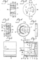
- Figures 1-6 illustrate various components of a metering valve according to the invention.
- the metering valve 1 see Fig. 7, is intended to extract a given volume of fluid from' a first fluid flow, for example blood extracted by suction through a test tube, and to then pass the extracted volume of fluid to a further fluid flow, for example a diluting fluid which is withdrawn by suction in a given quantity which is much greater than the volume of fluid extracted from the first flow.
- a first fluid flow for example blood extracted by suction through a test tube
- a further fluid flow for example a diluting fluid which is withdrawn by suction in a given quantity which is much greater than the volume of fluid extracted from the first flow.
- the metering valve includes a stationary valve component 2, see Figs. 1 and 2, which is provided with a first supply channel 3 and a first discharge channel 4, and a second supply channel 5 and a second discharge channel 6.
- the metering valve also incorporates a metering component 7 which can be rotated in relation to the stationary valve component and which is provided with a metering channel 8 having the aforesaid given volume, see Figs. 3 and 4.
- Fig. 4 illustrates the metering channel 8 turned on one side for the sake of clarity.
- the valve component 2 has a planar surface 9 in which channels 3-6 open out.
- the metering component'7 also has a planar surface 10 in which the two ends 11,12 of the metering channel 8 open out. When the valve is assembled, the planar surface 10 of the metering component 7 lies against the planar surface of the valve component 2, see Fig. 7.
- the ends 11,12 of the metering channel 8 are positioned so that in a first position of rotation of the metering component 7 relative to the valve component 2, the first supply channel 3 is connected to the first discharge channel 4 of the valve component 2, and so that in a second position of rotation of the metering component 7 in relation to the valve component 2, the metering channel connects the second supply channel 5 to the second discharge channel 6 of the valve component 2.
- the said first channels 3,4 are able to connect, for example, a suction line in a test tube containing blood with a suction pump.
- the said second channels are able to connect a vessel containing diluting fluid with a discharge line which opens into a collecting vessel for receiving diluted blood.
- the two rotational positions of the metering component may be displaced through 90° in relation to one another.
- the whole of the metering channel 8 may comprise a hose, preferably made of a plastics material.
- the hose 8 is inserted into axial holes 13,14 in the metering component 7, these holes opening into the planar surface 10.
- the volume to be extracted by the metering component 7 is varied primarily by varying the length of the hose 8 and secondly its inner diameter.
- the holes 13,14 of all metering components are suitably of mutually the same diameter, said metering components being intended to co-act, one by one, with one and the same valve component.
- a concentrically located chamber 15 is provided in the metering component 7 on the opposite side of the planar surface.
- This chamber 15 is intended to accommodate the hose 8.
- the chamber or space 15 is sealingly closed by a lid 16, which is placed on the metering component 7, see Fig. 7. This prevents contaminants from entering the metering component.
- the lid When the lid is applied it also lies against the hose 8, thereby rendering movement of the ends 11,12 of the hose 8 relative to the planar surface 10 difficult.
- the metering component 7 is made of a plastics material, preferably Teflon. This ensures an effective seal between the planar surface 10 of the metering component and the planar surface 9 of the valve component.
- the hose 8 is made from the same material as the metering component. Among other things this avoids movement of material between the hose and the metering component as a result variations in temperature. It has been found that the hose remains firmly seated in the metering component, when the hose and the metering component in general are made of "Teflon" and the holes 13,14 in the metering component have a diameter slightly smaller than the outer diameter of the hose 8.
- a sleeve 17 Arranged around the metering component 7 is a sleeve 17 which is arranged to press the planar surface 10 of the metering component against the planar surface 9 of the valve component.
- the sleeve 17 is therefore attached to the valve component 2.
- the sleeve is provided in its peripheral surface with two slots 18,19 which together with pins 20,21 projecting radially outwards from the valve component 2 form a bayonet fitting.
- a spring for example a leaf spring 22, which is arranged to press the metering component 7 against the valve component 2.
- the metering component 7 is also provided with a centrally located axial hole 23.
- the valve component 2 is also provided with a corresponding centrally located axial hole 24.
- a guide means 25 is suitably arranged in the hole 24 of the valve component, the inner diameter 26 of this guide means being equal to the inner diameter 27 of the hole 23 in the metering component 7.
- a drive shaft 28 extends through the two holes 23,24. Thus, the drive shaft 28 is rotatably arranged relative to the valve component 2.
- the drive shaft is non-rotatably connected to the metering component 7 through a slot 29 located in one end of the drive shaft 28 and co-acting with a pin 30 attached to the metering component and extending over one diameter of the hole 23 of the metering component. Consequently, rotation of the shaft 28 results in rotation of the metering component 7 relative to the stationary valve component 2.
- Fig. 7 illustrates an assembled metering valve in side view, where solely the sleeve 17 is shown in section. For the sake of clarity the channels and hose are not shown in broken lines.
- the metering valve illustrated in Fig. 7 is preferably mounted so as to project from the outer casing of a diluting apparatus.
- a metering component 7 having a hose 8 corresponding to said volume is mounted on the end of the drive shaft 28, whereafter the sleeve 17 is passed in over the metering component 7 and twisted so as to be connected to the valve component 2 through the aforesaid bayonet fitting.
- the drive shaft 28 is then rotated so as to move the metering component to the aforesaid first position of rotation. Blood is withdrawn by suction until the hose is filled. The drive shaft 28 then rotates the metering component to its second position of rotation. Diluting fluid is then pumped through the hose and into the aforesaid collecting vessel.
- the sleeve When desiring to extract a volume of fluid different to the aforesaid volume, the sleeve is removed by a simple manipulation of the hand and replaced with a further metering component, which in turn is secured by means of the sleeve. It will therewith be seen that the metering component can be exchanged or removed for cleaning the planar surfaces 9,10 in an extremely simple and rapid manner.
- metering component can be exchanged rapidly and simply, in combination with the fact that the metering component is inexpensive to manufacture, means that a large number of metering component of mutually different given volumes can be provided for use together with one and the same diluting apparatus, therefore enabling the apparatus to be used for different diluting processes.
- a first metering valve extracts a given volume of fluid, for example blood which is diluted, whereafter the second metering valve extracts a given volume of the diluted blood, this volume being diluted in its turn.
- the two metering components can be readily and quickly changed, it is possible to readily vary a total degree of dilution. For example, if ten metering components are available and all have mutually different extraction volume, these components can be combined two and two, so as to obtain forty-five different total degrees of dilution.
- a metering unit can be readily and quickly removed for cleaning purposes or for replacement with a unit of different volume.
- a large number of total degrees of dilution can be readily achieved without requiring access to a large number of expensive valves, as in the case when using known metering valves.
Landscapes
- Life Sciences & Earth Sciences (AREA)
- General Physics & Mathematics (AREA)
- Physics & Mathematics (AREA)
- Chemical & Material Sciences (AREA)
- Pathology (AREA)
- Analytical Chemistry (AREA)
- Biochemistry (AREA)
- General Health & Medical Sciences (AREA)
- Hydrology & Water Resources (AREA)
- Immunology (AREA)
- Health & Medical Sciences (AREA)
- Fluid Mechanics (AREA)
- Multiple-Way Valves (AREA)
- Sampling And Sample Adjustment (AREA)
- Check Valves (AREA)
- Investigating Or Analysing Biological Materials (AREA)
- Sliding Valves (AREA)
- Measuring Volume Flow (AREA)
- Infusion, Injection, And Reservoir Apparatuses (AREA)
Applications Claiming Priority (2)
| Application Number | Priority Date | Filing Date | Title |
|---|---|---|---|
| SE8405561A SE450853B (sv) | 1984-11-06 | 1984-11-06 | Doseringsventil for avskiljande av en viss bestemd vetskevolym fran ett forsta flode och tillforande av denna volym till ett andra flode |
| SE8405561 | 1984-11-06 |
Publications (2)
| Publication Number | Publication Date |
|---|---|
| EP0181299A2 true EP0181299A2 (de) | 1986-05-14 |
| EP0181299A3 EP0181299A3 (de) | 1988-05-25 |
Family
ID=20357641
Family Applications (1)
| Application Number | Title | Priority Date | Filing Date |
|---|---|---|---|
| EP85850335A Withdrawn EP0181299A3 (de) | 1984-11-06 | 1985-10-24 | Messhahn |
Country Status (4)
| Country | Link |
|---|---|
| US (1) | US4660424A (de) |
| EP (1) | EP0181299A3 (de) |
| JP (1) | JPS61165077A (de) |
| SE (1) | SE450853B (de) |
Cited By (3)
| Publication number | Priority date | Publication date | Assignee | Title |
|---|---|---|---|---|
| EP0336234A3 (de) * | 1988-04-04 | 1989-11-29 | Afora Oy | Vorrichtung zur kontinuierlichen Probenentnahme von Lauge aus einem Zellstoffkocher |
| WO1998039630A1 (en) * | 1997-03-04 | 1998-09-11 | Avecia Limited | Fluid transfer apparatus |
| EP1866620A4 (de) * | 2005-04-08 | 2015-11-25 | Boule Medical Ab | Vorrichtung zum auffüllen eines probevolumen definierenden geräts |
Families Citing this family (1)
| Publication number | Priority date | Publication date | Assignee | Title |
|---|---|---|---|---|
| AU2830297A (en) * | 1996-05-06 | 1997-11-26 | Daniel G. Cheresko | Oil and gas metering and measuring device |
Family Cites Families (10)
| Publication number | Priority date | Publication date | Assignee | Title |
|---|---|---|---|---|
| CH351420A (de) * | 1956-02-27 | 1961-01-15 | Perkin Elmer Corp | Probeentnahmevorrichtung |
| GB855234A (en) * | 1956-02-27 | 1960-11-30 | Perkin Elmer Corp | Sampling devices |
| US3475950A (en) * | 1966-02-14 | 1969-11-04 | Combustion Eng | Chromatograph sample system |
| US3567389A (en) * | 1968-04-03 | 1971-03-02 | Coulter Electronics | Fluid transfer valve structure |
| US4059009A (en) * | 1976-09-10 | 1977-11-22 | Micromeritics Instrument Corporation | Liquid chromatography system |
| SU603900A1 (ru) * | 1976-12-22 | 1978-04-25 | Предприятие П/Я В-8888 | Устройство дл дозировани проб в газовый хроматограф |
| US4152391A (en) * | 1977-12-16 | 1979-05-01 | Coulter Electronics, Inc. | Liquid transfer valve |
| US4411575A (en) * | 1981-05-01 | 1983-10-25 | The Perkin-Elmer Corporation | Sample transfer vessel |
| US4445391A (en) * | 1981-10-19 | 1984-05-01 | Coulter Electronics, Inc. | Liquid metering and transfer valve assembly |
| US4476731A (en) * | 1983-03-03 | 1984-10-16 | Scientific Systems, Inc. | Injection valve for liquid chromatographic column and system therefor |
-
1984
- 1984-11-06 SE SE8405561A patent/SE450853B/sv not_active IP Right Cessation
-
1985
- 1985-10-24 EP EP85850335A patent/EP0181299A3/de not_active Withdrawn
- 1985-11-01 US US06/793,766 patent/US4660424A/en not_active Expired - Fee Related
- 1985-11-05 JP JP60247871A patent/JPS61165077A/ja active Pending
Cited By (3)
| Publication number | Priority date | Publication date | Assignee | Title |
|---|---|---|---|---|
| EP0336234A3 (de) * | 1988-04-04 | 1989-11-29 | Afora Oy | Vorrichtung zur kontinuierlichen Probenentnahme von Lauge aus einem Zellstoffkocher |
| WO1998039630A1 (en) * | 1997-03-04 | 1998-09-11 | Avecia Limited | Fluid transfer apparatus |
| EP1866620A4 (de) * | 2005-04-08 | 2015-11-25 | Boule Medical Ab | Vorrichtung zum auffüllen eines probevolumen definierenden geräts |
Also Published As
| Publication number | Publication date |
|---|---|
| EP0181299A3 (de) | 1988-05-25 |
| JPS61165077A (ja) | 1986-07-25 |
| SE8405561L (sv) | 1986-05-07 |
| US4660424A (en) | 1987-04-28 |
| SE8405561D0 (sv) | 1984-11-06 |
| SE450853B (sv) | 1987-08-03 |
Similar Documents
| Publication | Publication Date | Title |
|---|---|---|
| EP0920906A1 (de) | Statischer Mischer | |
| JP4290880B2 (ja) | 4分の1ターン迅速接続フィッティング | |
| EP0029674B1 (de) | Flüssigkeitsprobennehmer und Pipeline oder Behälter mit diesem Probennehmer | |
| US5388972A (en) | Peristaltic pump with removable tubing of precise length | |
| EP3775831B1 (de) | Probenahmevorrichtung | |
| US2757541A (en) | Sampling apparatus | |
| US4726237A (en) | Fluid metering apparatus and method | |
| EP0466291A2 (de) | Vorrichtung und Verfahren zur Extraktion mit überkritischen Fluiden | |
| EP0089937A1 (de) | Verfahren und Vorrichtung zur fortgesetzten Verdünnung flüssiger Proben | |
| SE456041B (sv) | Ventilaggregat for metning och overforing av vetska for anvendning i ett utspedningssystem | |
| US3567389A (en) | Fluid transfer valve structure | |
| BR112012032729B1 (pt) | Dispositivo de amostragem | |
| US6247840B1 (en) | Dialysis container with sample saver | |
| US4660424A (en) | Metering valve | |
| RU2265821C2 (ru) | Устройство для взятия проб | |
| CN112005113A (zh) | 液相色谱模块中的集成柱和检测器 | |
| DE69113993T2 (de) | Ventil zum transfer und zur dosierung von flüssigkeiten. | |
| KR20040093169A (ko) | 유동 제한기 | |
| EP0508749A2 (de) | Probennahmeventil | |
| US9999887B2 (en) | Apparatus for analyzing a test liquid | |
| DE2123134A1 (de) | Anordnung zum Messen der Stromungs geschwindigkeit einer Flüssigkeit | |
| US5132014A (en) | Apparatus and method for supercritical fluid extraction | |
| US5616300A (en) | Priming and injection valve for analytical instruments | |
| US4682507A (en) | Material sampling apparatus | |
| US3803920A (en) | Sample dilution device-disc diluter |
Legal Events
| Date | Code | Title | Description |
|---|---|---|---|
| PUAI | Public reference made under article 153(3) epc to a published international application that has entered the european phase |
Free format text: ORIGINAL CODE: 0009012 |
|
| AK | Designated contracting states |
Kind code of ref document: A2 Designated state(s): AT BE CH DE FR GB IT LI LU NL |
|
| PUAL | Search report despatched |
Free format text: ORIGINAL CODE: 0009013 |
|
| RHK1 | Main classification (correction) |
Ipc: G01N 1/00 |
|
| AK | Designated contracting states |
Kind code of ref document: A3 Designated state(s): AT BE CH DE FR GB IT LI LU NL |
|
| STAA | Information on the status of an ep patent application or granted ep patent |
Free format text: STATUS: THE APPLICATION IS DEEMED TO BE WITHDRAWN |
|
| 18D | Application deemed to be withdrawn |
Effective date: 19890501 |
|
| RIN1 | Information on inventor provided before grant (corrected) |
Inventor name: PERMER, CHRISTER |