EP0181439A2 - Circuit de préréglage d'une tension de commande - Google Patents
Circuit de préréglage d'une tension de commande Download PDFInfo
- Publication number
- EP0181439A2 EP0181439A2 EP19850109957 EP85109957A EP0181439A2 EP 0181439 A2 EP0181439 A2 EP 0181439A2 EP 19850109957 EP19850109957 EP 19850109957 EP 85109957 A EP85109957 A EP 85109957A EP 0181439 A2 EP0181439 A2 EP 0181439A2
- Authority
- EP
- European Patent Office
- Prior art keywords
- voltage
- control
- switch
- output
- circuit
- Prior art date
- Legal status (The legal status is an assumption and is not a legal conclusion. Google has not performed a legal analysis and makes no representation as to the accuracy of the status listed.)
- Withdrawn
Links
- 230000000694 effects Effects 0.000 abstract description 4
- 238000000034 method Methods 0.000 abstract description 4
- 239000003990 capacitor Substances 0.000 description 4
- 230000003111 delayed effect Effects 0.000 description 1
- 230000001419 dependent effect Effects 0.000 description 1
- 230000005669 field effect Effects 0.000 description 1
- 238000012544 monitoring process Methods 0.000 description 1
Images
Classifications
-
- H—ELECTRICITY
- H03—ELECTRONIC CIRCUITRY
- H03G—CONTROL OF AMPLIFICATION
- H03G3/00—Gain control in amplifiers or frequency changers
-
- H—ELECTRICITY
- H03—ELECTRONIC CIRCUITRY
- H03L—AUTOMATIC CONTROL, STARTING, SYNCHRONISATION OR STABILISATION OF GENERATORS OF ELECTRONIC OSCILLATIONS OR PULSES
- H03L7/00—Automatic control of frequency or phase; Synchronisation
- H03L7/06—Automatic control of frequency or phase; Synchronisation using a reference signal applied to a frequency- or phase-locked loop
- H03L7/08—Details of the phase-locked loop
- H03L7/085—Details of the phase-locked loop concerning mainly the frequency- or phase-detection arrangement including the filtering or amplification of its output signal
- H03L7/093—Details of the phase-locked loop concerning mainly the frequency- or phase-detection arrangement including the filtering or amplification of its output signal using special filtering or amplification characteristics in the loop
-
- H—ELECTRICITY
- H03—ELECTRONIC CIRCUITRY
- H03L—AUTOMATIC CONTROL, STARTING, SYNCHRONISATION OR STABILISATION OF GENERATORS OF ELECTRONIC OSCILLATIONS OR PULSES
- H03L7/00—Automatic control of frequency or phase; Synchronisation
- H03L7/06—Automatic control of frequency or phase; Synchronisation using a reference signal applied to a frequency- or phase-locked loop
- H03L7/08—Details of the phase-locked loop
- H03L7/14—Details of the phase-locked loop for assuring constant frequency when supply or correction voltages fail
Definitions
- the invention relates to an arrangement for presetting an amplifier, as used, for example, as a regulator in a phase locked loop.
- VCO voltage-controlled oscillator
- the switch S1 and - if present S2 - is actuated by a switching criterion acting from the outside, which can be, for example, level monitoring of the input signal voltage E.
- a switching criterion acting from the outside which can be, for example, level monitoring of the input signal voltage E.
- a direct reaction of the switches to failures of the components shown is not intended either by the arrangement according to the invention or by the two internally known solutions shown.
- the invention has for its object to provide a circuit of the type mentioned, in which on the one hand the preset control voltage U3 is adhered to as precisely as possible in the switch-off state, and on the other hand the DC voltages applied to the control amplifier N1 and the capacitor C come close to the values of the operating case.
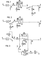
- a switch S is in the in 'series to the output of the control amplifier N1 mounted behind which a voltage U2 determined by an internal resistor R4, the size of the control voltage U3, the switch S is opened provided.
- voltage U2 has no effect because of the low-impedance output of control amplifier N1.
- the voltage U4 shown in FIG. 2 will usually deviate noticeably from its previous value.
- the resulting charging of the capacitor C has a disadvantageous effect if it is subsequently switched back to the normal operating mode.
- Figure 2 shows a further possibility in which the input of the control amplifier N1 between the output voltage of the converter U and an auxiliary voltage U2 is switched.
- the generally high DC voltage gain of the connected control amplifier N1 has a disadvantageous effect, since the voltage U3 becomes more dependent on fluctuations in the voltage U2 and the reference voltage U B applied to the control amplifier N1.
- the controlled variable is present at input E of the circuit.
- the control voltage for the manipulated variable is tapped at output A.
- the converter U arranged at the input supplies an output voltage proportional to the controlled variable.
- the output f of the first control amplifier N1 is connected to the one input g of the second control amplifier N2.
- Its output h is connected via a switch S1 to an input i of the first control amplifier N2.
- the sum of the operating phases in this loop circuit goes against a limit of -180 ° for lower frequencies.
- the large sum of the loop gains of the amplifiers N1 and N2 also guarantee a high accuracy of the control voltage U3.
- the circuit according to the invention shows good dynamic behavior when switching between the shutdown and operating state.
Landscapes
- Dc-Dc Converters (AREA)
- Stabilization Of Oscillater, Synchronisation, Frequency Synthesizers (AREA)
Applications Claiming Priority (2)
| Application Number | Priority Date | Filing Date | Title |
|---|---|---|---|
| DE19843441143 DE3441143A1 (de) | 1984-11-10 | 1984-11-10 | Schaltung zur voreinstellung einer regelspannung |
| DE3441143 | 1984-11-10 |
Publications (1)
| Publication Number | Publication Date |
|---|---|
| EP0181439A2 true EP0181439A2 (fr) | 1986-05-21 |
Family
ID=6250002
Family Applications (1)
| Application Number | Title | Priority Date | Filing Date |
|---|---|---|---|
| EP19850109957 Withdrawn EP0181439A2 (fr) | 1984-11-10 | 1985-08-07 | Circuit de préréglage d'une tension de commande |
Country Status (3)
| Country | Link |
|---|---|
| EP (1) | EP0181439A2 (fr) |
| DE (1) | DE3441143A1 (fr) |
| DK (1) | DK516885A (fr) |
Cited By (3)
| Publication number | Priority date | Publication date | Assignee | Title |
|---|---|---|---|---|
| EP0313129A3 (en) * | 1987-10-17 | 1989-09-06 | Philips Patentverwaltung Gmbh | Phase-locked loop with a voltage-controlled oscillator |
| EP0536027A1 (fr) * | 1991-10-04 | 1993-04-07 | Thomson-Csf | Procédé et dispositif d'annulation de l'erreur de phase sur le déphasage entre les signaux d'entrée et de sortie d'une boucle à verrouillage de phase |
| WO2001031792A3 (fr) * | 1999-10-29 | 2002-01-03 | Adc Telecommunications Inc | Systemes et procedes relatifs a des circuits de maintien dans des boucles a phase asservie |
Families Citing this family (2)
| Publication number | Priority date | Publication date | Assignee | Title |
|---|---|---|---|---|
| DE3822293A1 (de) * | 1988-07-01 | 1990-01-04 | Bosch Gmbh Robert | Digitaler phasenregelkreis |
| JPH06197014A (ja) * | 1992-12-25 | 1994-07-15 | Mitsubishi Electric Corp | 位相同期回路 |
-
1984
- 1984-11-10 DE DE19843441143 patent/DE3441143A1/de not_active Withdrawn
-
1985
- 1985-08-07 EP EP19850109957 patent/EP0181439A2/fr not_active Withdrawn
- 1985-11-08 DK DK516885A patent/DK516885A/da not_active Application Discontinuation
Cited By (5)
| Publication number | Priority date | Publication date | Assignee | Title |
|---|---|---|---|---|
| EP0313129A3 (en) * | 1987-10-17 | 1989-09-06 | Philips Patentverwaltung Gmbh | Phase-locked loop with a voltage-controlled oscillator |
| EP0536027A1 (fr) * | 1991-10-04 | 1993-04-07 | Thomson-Csf | Procédé et dispositif d'annulation de l'erreur de phase sur le déphasage entre les signaux d'entrée et de sortie d'une boucle à verrouillage de phase |
| FR2682235A1 (fr) * | 1991-10-04 | 1993-04-09 | Thomson Csf | Procede et dispositif d'annulation de l'erreur de phase sur le dephasage entre les signaux d'entree et de sortie d'une boucle a verrouillage de phase. |
| WO2001031792A3 (fr) * | 1999-10-29 | 2002-01-03 | Adc Telecommunications Inc | Systemes et procedes relatifs a des circuits de maintien dans des boucles a phase asservie |
| US7010076B1 (en) | 1999-10-29 | 2006-03-07 | Adc Telecommunications, Inc. | Systems and methods for holdover circuits in phase locked loops |
Also Published As
| Publication number | Publication date |
|---|---|
| DK516885D0 (da) | 1985-11-08 |
| DK516885A (da) | 1986-05-11 |
| DE3441143A1 (de) | 1986-05-22 |
Similar Documents
| Publication | Publication Date | Title |
|---|---|---|
| DE69626991T2 (de) | Leistungstransistorsteuerschaltung für Spannungsregler | |
| DE3025100A1 (de) | Verstaerker | |
| DE3131574A1 (de) | "stromregelschaltung fuer einen ueber eine leistungstreiberstufe gesteuerten verbraucher" | |
| DE2620191C2 (de) | Schaltnetzteil für die Versorgung eines Fernsehgerätes | |
| DE1291412B (de) | Hochfrequenzgenerator | |
| EP0181439A2 (fr) | Circuit de préréglage d'une tension de commande | |
| DE1139553B (de) | Breitbandiger Frequenzteiler | |
| DE2330776A1 (de) | Schaltung zur zuruecknahme einer belastung mit variabler geschwindigkeit | |
| DE60114733T2 (de) | Phasenregelschleife mit verringerter Verriegelungszeit | |
| DE2930216C2 (fr) | ||
| EP0737379A1 (fr) | Transformateur de tension | |
| DE3333223A1 (de) | Schaltregler mit einem komparator, dem eine periodische vergleichsgroesse mit vorgegebenem zeitlichen verlauf zugefuehrt ist | |
| DE3112502A1 (de) | Saegezahngenerator | |
| AT369202B (de) | Elektronische synchronisierschlatungsanordnung zum parallelschalten von zwei wechselstromnetzen bzw. zum zuschalten von einem halbleiter-wechsel- richter an ein in betrieb befindliches wechsel- stromnetz | |
| DE2757505A1 (de) | Roentgendiagnostikgenerator, bei dem die roentgenroehrenspannung ueber den roentgenroehrenstrom geregelt wird | |
| DE19841972A1 (de) | Getakteter Shuntregler | |
| DE2449376C2 (de) | HF-Generator mit Spannungsstabilisierung | |
| EP0533981B1 (fr) | Récepteur haute fréquence | |
| DE3218448A1 (de) | Schaltungsanordnung mit einem bei ueberschreitung kritischer stoergroessenwerte stillsetzbaren schaltregler | |
| DE3220553C2 (de) | Sägezahngenerator | |
| EP0122541B1 (fr) | Circuit d'alimentation en courant | |
| EP0495141B1 (fr) | Dispositif de réglage d'amplitude | |
| DE3544622A1 (de) | Schaltungsanordnung fuer eine digitale pll-schaltung mit verkuerzter einrastdauer | |
| DE2527099C3 (de) | Vertikalablenkschaltung für einen Fernsehempfänger | |
| DE3709382A1 (de) | Verfahren zur bildung der einschaltsignale fuer die halbleiterschalter eines wechselrichters |
Legal Events
| Date | Code | Title | Description |
|---|---|---|---|
| PUAI | Public reference made under article 153(3) epc to a published international application that has entered the european phase |
Free format text: ORIGINAL CODE: 0009012 |
|
| AK | Designated contracting states |
Kind code of ref document: A2 Designated state(s): AT CH LI NL |
|
| STAA | Information on the status of an ep patent application or granted ep patent |
Free format text: STATUS: THE APPLICATION HAS BEEN WITHDRAWN |
|
| 18W | Application withdrawn |
Withdrawal date: 19870904 |
|
| RIN1 | Information on inventor provided before grant (corrected) |
Inventor name: RUTHEMANN, KLAUS, DIPL.-ING. |