EP0181607B1 - Dispositif pour la fixation des rails de chemin de fer sur des traverses en acier en forme d'Y - Google Patents
Dispositif pour la fixation des rails de chemin de fer sur des traverses en acier en forme d'Y Download PDFInfo
- Publication number
- EP0181607B1 EP0181607B1 EP85114169A EP85114169A EP0181607B1 EP 0181607 B1 EP0181607 B1 EP 0181607B1 EP 85114169 A EP85114169 A EP 85114169A EP 85114169 A EP85114169 A EP 85114169A EP 0181607 B1 EP0181607 B1 EP 0181607B1
- Authority
- EP
- European Patent Office
- Prior art keywords
- sleeper
- cross
- screw
- piece member
- steel
- Prior art date
- Legal status (The legal status is an assumption and is not a legal conclusion. Google has not performed a legal analysis and makes no representation as to the accuracy of the status listed.)
- Expired
Links
- 229910000831 Steel Inorganic materials 0.000 title claims abstract description 25
- 239000010959 steel Substances 0.000 title claims abstract description 25
- 241001669679 Eleotris Species 0.000 claims abstract description 27
- 239000004033 plastic Substances 0.000 claims abstract description 7
- 229920003023 plastic Polymers 0.000 claims abstract description 7
- 239000000463 material Substances 0.000 claims abstract 3
- 230000002787 reinforcement Effects 0.000 claims description 4
- 239000003000 extruded plastic Substances 0.000 claims 1
- 239000002991 molded plastic Substances 0.000 claims 1
- 239000004567 concrete Substances 0.000 description 3
- XEEYBQQBJWHFJM-UHFFFAOYSA-N Iron Chemical compound [Fe] XEEYBQQBJWHFJM-UHFFFAOYSA-N 0.000 description 2
- 239000000835 fiber Substances 0.000 description 2
- 238000002347 injection Methods 0.000 description 2
- 239000007924 injection Substances 0.000 description 2
- 238000004519 manufacturing process Methods 0.000 description 2
- 230000008719 thickening Effects 0.000 description 2
- 238000003466 welding Methods 0.000 description 2
- 238000005452 bending Methods 0.000 description 1
- 239000011230 binding agent Substances 0.000 description 1
- 238000010276 construction Methods 0.000 description 1
- 239000004744 fabric Substances 0.000 description 1
- 239000011210 fiber-reinforced concrete Substances 0.000 description 1
- 239000003365 glass fiber Substances 0.000 description 1
- 229910052742 iron Inorganic materials 0.000 description 1
- 229920000642 polymer Polymers 0.000 description 1
Images



Classifications
-
- E—FIXED CONSTRUCTIONS
- E01—CONSTRUCTION OF ROADS, RAILWAYS, OR BRIDGES
- E01B—PERMANENT WAY; PERMANENT-WAY TOOLS; MACHINES FOR MAKING RAILWAYS OF ALL KINDS
- E01B9/00—Fastening rails on sleepers, or the like
- E01B9/02—Fastening rails, tie-plates, or chairs directly on sleepers or foundations; Means therefor
- E01B9/32—Fastening on steel sleepers with clamp members
- E01B9/34—Fastening on steel sleepers with clamp members by resilient steel clips
-
- E—FIXED CONSTRUCTIONS
- E01—CONSTRUCTION OF ROADS, RAILWAYS, OR BRIDGES
- E01B—PERMANENT WAY; PERMANENT-WAY TOOLS; MACHINES FOR MAKING RAILWAYS OF ALL KINDS
- E01B3/00—Transverse or longitudinal sleepers; Other means resting directly on the ballastway for supporting rails
- E01B3/16—Transverse or longitudinal sleepers; Other means resting directly on the ballastway for supporting rails made from steel
Definitions
- the invention relates to a device of the type mentioned in the preamble of claim 1 for fastening rails on Y-steel sleepers.
- a device of this type is known from the Luxembourg patent specification 81 085, in which the traverse can be made of steel with two tubular parts with screw holes and a web connecting these parts or a steel fiber concrete block into which screw dowels for the sleeper screws are cast at a suitable distance from one another.
- Such crossbeams are each laterally inserted at a fastening point between the rail and a Y-steel sleeper into a cavity which is formed between two steel support parts which are H-shaped in cross section and are connected at a distance from one another in the region of a fastening point.
- the upper legs with their mutually facing edges form a slot between them, which forms an opening for the sleeper screws.
- the crossbeam When fastened, the crossbeam lies from the inside on the upper inner legs of the two H-beam parts.
- a cross member designed as a steel fiber concrete part or welded steel part is relatively expensive and complex to manufacture. If the concrete part cracks or breaks, the screw anchors can loosen. Such cracks and breaks result from changing loads and weather influences.
- the steel crossbar is very rigid. When tightening or loosening the steel spring that clamps the rail foot, bending and torsional forces act on the sleeper screws. These destroy the screw and / or the screw anchors. With both types, parts have to be replaced after some time.
- the invention has for its object to improve a device of the type mentioned above for fastening rails on Y-steel sleepers with regard to their durability, reliability and manufacturing costs and to achieve that during the long life of sleepers and rails, the sleeper screws in the crossmember several times can be loosened, tightened and tightened without causing damage.
- the design of the traverse made of plastic means a considerable cost saving compared to the traverse made of steel fiber reinforced concrete or steel, while at the same time increasing durability and reliability.
- the screw anchors or the screws can be easily screwed into the bores of the tubular parts, and when screw-in screw anchors are screwed in, a pressure is also applied, so that an increase in the frictional engagement is achieved.
- the two screw holes are inclined towards one another in the screwing direction.
- the traverse can consist of a single piece made of injection molded or cast plastic.
- tubular parts of the crossmember have a widened cross section in the region of their contact surface against the sleepers in order to enlarge these contact surfaces.
- tubular parts may be provided with internal or external reinforcement, for example in the form of rings, pipe sections, fabric or the like.
- Fig. 1 partially shows one
- FIG. 2 is an enlarged top view in section 11 for the rail 2.
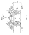
- FIG. 3 is a section 111-111 through FIG. 2
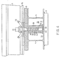
- FIG. 4 is a section IV-IV through FIG. 2.
- the elements 4 and 5 made of H-steel profiles are connected by bolts 8 and 9 on the top and bolts 10 and 11 on the bottom at a distance by welding.
- a slot 12 is formed by the distance, the width of which is slightly larger than the diameter of sleeper screws 13 and 14.
- the rail 1 rests with its foot 15 on a base plate 16 made of plastic, which in turn rests on a slightly wedge-shaped base plate 17 which rests on an upper cross part 18 of the element 5.
- the bolt 8 has an inclined edge 19, between which and the foot 15 a guide plate 20 is located in a corresponding manner between one inclined edge 21 of the bolt 9 and the foot 15 a guide plate 22.
- Tension clamps 23 and 24 are each drawn through the heads of the sleeper screws 13 and 14 against the foot 15 of the rail 1 while they are on the other side of the sleeper screws 13 and 14 respectively Support on the guide plates 20 and 22 so that the foot 15 is resiliently pulled against the cross member 18.
- a cross member 26 is inserted from the outside into a free space 25 between the elements 4 and 5.
- the cross member 26 consists of two pipe sections 27 and 28 which are connected to one another by means of webs 29 and 30 made of flat iron by welding.
- the web 30 extends over the entire underside of the pipe sections 27 and 28 and also engages in a leading manner in a slot 33 formed between two lower transverse parts 31 and 32, so that the crossmember is guided against lateral movements.
- the underside of the tube pieces 27 and 28 is closed by floor plates 34 and 35, which are welded to both the tube pieces and the web 30.
- screw anchors 36 and 37 which are embedded in the interior of the pipe sections 27 and 28 by a binding agent 38 and 39.
- the screw anchors 36 and 37 also have external threads 40 and 41. If necessary, the binding in the area of the external thread can also be designed in such a way that the screw anchors 36 and 37 can themselves be screwed in and out.
- the threshold screws 13 and 14 are screwed into the screw bolts 36 and 37 with their screw threads 42 and 43, respectively.
- the bolts 36 and 37 are slightly inclined in the direction of the elements 4 and 5, so that they are adapted to the angle of inclination of the lower rail flanges.
- FIG. 5 shows, according to the invention, a crossmember 52 which has two tubular parts 53 and 54 in which bores 56 are provided centrally, optionally with an internal thread 55, for screwing in the screw threads 42, 43 of sleeper screws 13, 14 (FIGS. 2-4) are and which together with a web 57 form a piece that is cast or injection molded from plastic.
- the tubular parts 53 and 54 have a larger cross section, so that flange-shaped thickenings 60 and 61 are formed, which serve to enlarge the contact surfaces 58 and 59 and also to reinforce them.
- ring-shaped reinforcements 62 in the area of the thickenings 60 and 61, which are made of steel, glass fiber or the like and can also have other shapes familiar to the person skilled in the art.
Landscapes
- Engineering & Computer Science (AREA)
- Architecture (AREA)
- Civil Engineering (AREA)
- Structural Engineering (AREA)
- Mechanical Engineering (AREA)
- Bridges Or Land Bridges (AREA)
- Machines For Laying And Maintaining Railways (AREA)
- Train Traffic Observation, Control, And Security (AREA)
Claims (5)
Priority Applications (1)
| Application Number | Priority Date | Filing Date | Title |
|---|---|---|---|
| AT85114169T ATE43663T1 (de) | 1984-11-08 | 1985-11-07 | Vorrichtung zur befestigung von schienen einer eisenbahn auf y-stahlschwellen. |
Applications Claiming Priority (2)
| Application Number | Priority Date | Filing Date | Title |
|---|---|---|---|
| DE3440789 | 1984-11-08 | ||
| DE3440789 | 1984-11-08 |
Publications (2)
| Publication Number | Publication Date |
|---|---|
| EP0181607A1 EP0181607A1 (fr) | 1986-05-21 |
| EP0181607B1 true EP0181607B1 (fr) | 1989-05-31 |
Family
ID=6249780
Family Applications (1)
| Application Number | Title | Priority Date | Filing Date |
|---|---|---|---|
| EP85114169A Expired EP0181607B1 (fr) | 1984-11-08 | 1985-11-07 | Dispositif pour la fixation des rails de chemin de fer sur des traverses en acier en forme d'Y |
Country Status (3)
| Country | Link |
|---|---|
| EP (1) | EP0181607B1 (fr) |
| AT (1) | ATE43663T1 (fr) |
| DE (1) | DE3570710D1 (fr) |
Families Citing this family (2)
| Publication number | Priority date | Publication date | Assignee | Title |
|---|---|---|---|---|
| DE4116306A1 (de) * | 1991-05-15 | 1992-11-19 | Salzgitter Peine Stahlwerke | Vormontierbare schienenbefestigung |
| CN111532978B (zh) * | 2020-06-11 | 2025-03-14 | 中铁七局集团广州工程有限公司 | 一种快装组合式龙门吊轨道基础 |
Family Cites Families (6)
| Publication number | Priority date | Publication date | Assignee | Title |
|---|---|---|---|---|
| FR349974A (fr) * | 1904-06-10 | 1905-08-18 | Gauchet A | Système de traverses métalliques pour voies ferrées |
| GB159558A (en) * | 1919-11-18 | 1921-02-18 | Uriah Oscar Long | Improvements in railway sleepers |
| US1697398A (en) * | 1928-05-26 | 1929-01-01 | Frank G Metcalf | Insulating rail connection for metal ties |
| DE659135C (de) * | 1935-12-05 | 1938-04-26 | Valentin Anton Petkovic Dr | Schienenbefestigung auf einer eisernen Schwelle in T-Form |
| LU81085A1 (de) * | 1979-03-28 | 1980-04-21 | Arbed | Zur befestigung von eisenbahnschienen auf stahlschwellen geeignetes befestigungssystem |
| NL8202093A (nl) * | 1982-05-21 | 1983-12-16 | Philips Nv | Klem voor het bevestigen van spoorrails, werkwijze voor het vervaardigen van een klem. |
-
1985
- 1985-11-07 DE DE8585114169T patent/DE3570710D1/de not_active Expired
- 1985-11-07 AT AT85114169T patent/ATE43663T1/de not_active IP Right Cessation
- 1985-11-07 EP EP85114169A patent/EP0181607B1/fr not_active Expired
Also Published As
| Publication number | Publication date |
|---|---|
| DE3570710D1 (en) | 1989-07-06 |
| ATE43663T1 (de) | 1989-06-15 |
| EP0181607A1 (fr) | 1986-05-21 |
Similar Documents
| Publication | Publication Date | Title |
|---|---|---|
| DE3720381A1 (de) | Vorrichtung zur befestigung von eisenbahnschienen auf fester fahrbahn | |
| DE2803021A1 (de) | Baugruppe zur bildung eines niveaugleichen uebergangs einer strasse ueber ein bahnschienenpaar | |
| DE3619417A1 (de) | Betonschwelle | |
| DE1994725U (de) | Fugendichtungsleiste zur verwendung beim strassen- und brueckendeckenbau | |
| DE1911259A1 (de) | Befestigungsvorrichtung fuer eine stromfuehrende Schiene | |
| DE1295579B (de) | Vorrichtung zum UEberbruecken von Dehnungsfugen, insbesondere in Bruecken | |
| CH620004A5 (en) | Railway sleeper | |
| DE3521673C2 (fr) | ||
| EP0181607B1 (fr) | Dispositif pour la fixation des rails de chemin de fer sur des traverses en acier en forme d'Y | |
| AT404266B (de) | Schienengleicher bahnübergang | |
| DE102012223844A1 (de) | Temporäre hilfsbrücken-abstützeinrichtung für gleisabschnitte | |
| EP1026321A1 (fr) | Raccord en acier pour traverses de chemins de fer, notamment traverses en béton précontraint pour aiguillages | |
| DE19508108A1 (de) | Zweiblock-Schwelle | |
| DE102007048042B3 (de) | Rillenschienenkreuzungsbereich | |
| DE3426550C2 (fr) | ||
| DE8432697U1 (de) | Vorrichtung zur befestigung von schienen einer eisenbahn auf stahlschwellen, insbesondere auf y-stahlschwellen | |
| LU81085A1 (de) | Zur befestigung von eisenbahnschienen auf stahlschwellen geeignetes befestigungssystem | |
| DE4317495A1 (de) | Schwelle | |
| DE4236191A1 (de) | Bahnkörper | |
| AT255468B (de) | Fahrschienenbefestigung an Betonschwellen oder Betondecken | |
| DE8517651U1 (de) | Vorrichtung zur Befestigung von Schienen einer Eisenbahn auf Stahlschwellen, insbesondere auf Y-Stahlschwellen | |
| DE8615554U1 (de) | Betonschwelle | |
| DE19828302C2 (de) | Flüssigkeitsdichtes Großflächenplattensystem aus rechteckigen, insbesondere quadratischen Betonplatten | |
| DE3828440C1 (en) | Sleeper made of flanged steel girders | |
| EP0759106B1 (fr) | Fixation de rails |
Legal Events
| Date | Code | Title | Description |
|---|---|---|---|
| PUAI | Public reference made under article 153(3) epc to a published international application that has entered the european phase |
Free format text: ORIGINAL CODE: 0009012 |
|
| AK | Designated contracting states |
Kind code of ref document: A1 Designated state(s): AT BE CH DE FR GB IT LI NL SE |
|
| RIN1 | Information on inventor provided before grant (corrected) |
Inventor name: WEDEKIND, GERHARD Inventor name: FRENZEL, JUERGEN Inventor name: FASTERDING, GUENTER |
|
| 17P | Request for examination filed |
Effective date: 19861124 |
|
| 17Q | First examination report despatched |
Effective date: 19880115 |
|
| GRAA | (expected) grant |
Free format text: ORIGINAL CODE: 0009210 |
|
| AK | Designated contracting states |
Kind code of ref document: B1 Designated state(s): AT BE CH DE FR GB IT LI NL SE |
|
| REF | Corresponds to: |
Ref document number: 43663 Country of ref document: AT Date of ref document: 19890615 Kind code of ref document: T |
|
| REF | Corresponds to: |
Ref document number: 3570710 Country of ref document: DE Date of ref document: 19890706 |
|
| ET | Fr: translation filed | ||
| ITF | It: translation for a ep patent filed | ||
| GBT | Gb: translation of ep patent filed (gb section 77(6)(a)/1977) | ||
| PLBE | No opposition filed within time limit |
Free format text: ORIGINAL CODE: 0009261 |
|
| STAA | Information on the status of an ep patent application or granted ep patent |
Free format text: STATUS: NO OPPOSITION FILED WITHIN TIME LIMIT |
|
| 26N | No opposition filed | ||
| ITTA | It: last paid annual fee | ||
| EAL | Se: european patent in force in sweden |
Ref document number: 85114169.7 |
|
| PGFP | Annual fee paid to national office [announced via postgrant information from national office to epo] |
Ref country code: FR Payment date: 19961010 Year of fee payment: 12 |
|
| PGFP | Annual fee paid to national office [announced via postgrant information from national office to epo] |
Ref country code: AT Payment date: 19961015 Year of fee payment: 12 |
|
| PGFP | Annual fee paid to national office [announced via postgrant information from national office to epo] |
Ref country code: SE Payment date: 19961018 Year of fee payment: 12 |
|
| PGFP | Annual fee paid to national office [announced via postgrant information from national office to epo] |
Ref country code: BE Payment date: 19961021 Year of fee payment: 12 |
|
| PGFP | Annual fee paid to national office [announced via postgrant information from national office to epo] |
Ref country code: GB Payment date: 19961022 Year of fee payment: 12 |
|
| PGFP | Annual fee paid to national office [announced via postgrant information from national office to epo] |
Ref country code: NL Payment date: 19961024 Year of fee payment: 12 |
|
| PGFP | Annual fee paid to national office [announced via postgrant information from national office to epo] |
Ref country code: CH Payment date: 19961028 Year of fee payment: 12 |
|
| PGFP | Annual fee paid to national office [announced via postgrant information from national office to epo] |
Ref country code: DE Payment date: 19961116 Year of fee payment: 12 |
|
| PG25 | Lapsed in a contracting state [announced via postgrant information from national office to epo] |
Ref country code: GB Free format text: LAPSE BECAUSE OF NON-PAYMENT OF DUE FEES Effective date: 19971107 Ref country code: AT Free format text: LAPSE BECAUSE OF NON-PAYMENT OF DUE FEES Effective date: 19971107 |
|
| PG25 | Lapsed in a contracting state [announced via postgrant information from national office to epo] |
Ref country code: SE Free format text: LAPSE BECAUSE OF NON-PAYMENT OF DUE FEES Effective date: 19971108 |
|
| PG25 | Lapsed in a contracting state [announced via postgrant information from national office to epo] |
Ref country code: LI Free format text: LAPSE BECAUSE OF NON-PAYMENT OF DUE FEES Effective date: 19971130 Ref country code: FR Free format text: THE PATENT HAS BEEN ANNULLED BY A DECISION OF A NATIONAL AUTHORITY Effective date: 19971130 Ref country code: CH Free format text: LAPSE BECAUSE OF NON-PAYMENT OF DUE FEES Effective date: 19971130 Ref country code: BE Free format text: LAPSE BECAUSE OF NON-PAYMENT OF DUE FEES Effective date: 19971130 |
|
| BERE | Be: lapsed |
Owner name: STAHLWERKE PEINE-SALZGITTER A.G. Effective date: 19971130 |
|
| PG25 | Lapsed in a contracting state [announced via postgrant information from national office to epo] |
Ref country code: NL Free format text: LAPSE BECAUSE OF NON-PAYMENT OF DUE FEES Effective date: 19980601 |
|
| GBPC | Gb: european patent ceased through non-payment of renewal fee |
Effective date: 19971107 |
|
| REG | Reference to a national code |
Ref country code: CH Ref legal event code: PL |
|
| PG25 | Lapsed in a contracting state [announced via postgrant information from national office to epo] |
Ref country code: DE Free format text: LAPSE BECAUSE OF NON-PAYMENT OF DUE FEES Effective date: 19980801 |
|
| EUG | Se: european patent has lapsed |
Ref document number: 85114169.7 |
|
| NLV4 | Nl: lapsed or anulled due to non-payment of the annual fee |
Effective date: 19980601 |
|
| REG | Reference to a national code |
Ref country code: FR Ref legal event code: ST |