EP0181623B1 - Dispositif auxiliaire pour fraiser des rainures pour assembler des planches à angle droit - Google Patents
Dispositif auxiliaire pour fraiser des rainures pour assembler des planches à angle droit Download PDFInfo
- Publication number
- EP0181623B1 EP0181623B1 EP85114264A EP85114264A EP0181623B1 EP 0181623 B1 EP0181623 B1 EP 0181623B1 EP 85114264 A EP85114264 A EP 85114264A EP 85114264 A EP85114264 A EP 85114264A EP 0181623 B1 EP0181623 B1 EP 0181623B1
- Authority
- EP
- European Patent Office
- Prior art keywords
- alignment
- slits
- auxiliary device
- table support
- cutter
- Prior art date
- Legal status (The legal status is an assumption and is not a legal conclusion. Google has not performed a legal analysis and makes no representation as to the accuracy of the status listed.)
- Expired
Links
- 230000013011 mating Effects 0.000 claims 2
- 241000826860 Trapezium Species 0.000 claims 1
- 238000003801 milling Methods 0.000 abstract description 15
- 239000002023 wood Substances 0.000 description 4
- 238000005259 measurement Methods 0.000 description 2
- 230000006978 adaptation Effects 0.000 description 1
- 238000004519 manufacturing process Methods 0.000 description 1
Images


Classifications
-
- B—PERFORMING OPERATIONS; TRANSPORTING
- B27—WORKING OR PRESERVING WOOD OR SIMILAR MATERIAL; NAILING OR STAPLING MACHINES IN GENERAL
- B27F—DOVETAILED WORK; TENONS; SLOTTING MACHINES FOR WOOD OR SIMILAR MATERIAL; NAILING OR STAPLING MACHINES
- B27F1/00—Dovetailed work; Tenons; Making tongues or grooves; Groove- and- tongue jointed work; Finger- joints
- B27F1/08—Making dovetails, tongues, or tenons, of definite limited length
- B27F1/12—Corner- locking mechanisms, i.e. machines for cutting crenellated joints
-
- Y—GENERAL TAGGING OF NEW TECHNOLOGICAL DEVELOPMENTS; GENERAL TAGGING OF CROSS-SECTIONAL TECHNOLOGIES SPANNING OVER SEVERAL SECTIONS OF THE IPC; TECHNICAL SUBJECTS COVERED BY FORMER USPC CROSS-REFERENCE ART COLLECTIONS [XRACs] AND DIGESTS
- Y10—TECHNICAL SUBJECTS COVERED BY FORMER USPC
- Y10T—TECHNICAL SUBJECTS COVERED BY FORMER US CLASSIFICATION
- Y10T409/00—Gear cutting, milling, or planing
- Y10T409/30—Milling
- Y10T409/303416—Templet, tracer, or cutter
- Y10T409/303696—Templet
Definitions
- the invention relates to an auxiliary device for milling grooves in right-angled planks for comb-corner connections by means of a hand-held milling cutter, on the workbench side consisting of a right-angled guide part with a table support plate and a back plate, both plates being comb-like with slots which are flush in the area of the corner angle merge into one another, and on the milling cutter side consists of a guide piece guided in the slots.
- auxiliary device for milling such corner connections by means of a hand-held router which on the workbench side consists of a right-angled guide part with a table support plate and a back plate. Both plates are comb-like with slots that merge into one another in the area of the corner angle. A guide piece is provided on the cutter side and is guided in the slots.
- this device it is possible to mill out the grooves in the longitudinal and transverse wood with the required relative positional accuracy without complex calculations and measurements, however, the second board to be machined must be clamped together with the guide piece on the workbench side by exactly half the groove spacing, if e.g. two boards of the same width are to be joined flush. This still requires certain alignment work and leaves room for error.
- the invention has for its object to improve the generic auxiliary device in such a way that the correct alignment of the second board to be processed results inevitably and foolproof.
- this object is achieved in that the table support plate is provided on its free edge facing away from the corner angle with at least one alignment finger projecting parallel to the extension of the slots of the table support plate, which, offset from the slots by a gap, is aligned with a prong spacing two slots lies and whose cross-section is adapted to the contour of the groove to be milled.
- the grooves in the longitudinal wood can first be milled in the usual way. Then this first board is turned over and placed with the groove side - with flush side edges - on the second board.
- the alignment of the auxiliary device for milling the transverse grooves in the second board is now achieved by inserting the alignment finger into a groove of the first board. In this way, the grooves and tines of the two boards can be correctly and dimensionally allocated without taking any measurements and without complicated alignment work, taking into account their flushness - or a desired edge overhang.
- two alignment fingers can be arranged in the middle of the table top, the center distance of which is equal to the center distance between two adjacent slots.
- the arrangement of two alignment fingers improves the guiding accuracy of the auxiliary device, and due to the adjacent position of the alignment fingers, this advantage also with very narrow corner connections, i.e. narrow boards, can take effect.
- one or two further alignment fingers can be provided in the outer region of the table support plate. These additional alignment fingers improve the contact between the longitudinal timber and the auxiliary device in the case of wide corner connections.
- the alignment finger (s) can have a trapezoidal cross section, the smaller base lying in the table support plane of the table support plate.
- This trapezoidal cross section is adapted in a special way to suitably designed dovetail grooves.
- this embodiment can also be associated with a cylindrical end mill, the diameter of which is equal to the length of the large trapezoidal base. As a result, both frustoconical and cylindrical end mills can be used with the same auxiliary device.
- the alignment finger or fingers can have a rectangular cross section.
- This contour is particularly suitable for milling rectangular grooves.
- a frustoconical end mill can also be used, the smallest diameter of which is equal to the width of the rectangular cross section.
- the use for both types of grooves is possible.
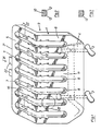
- Fig. 1 shows a perspective view of the guide part 1 of an auxiliary device for milling grooves in rectangular planks for comb-corner joints.
- the guide part has the basic shape of a U-shaped screw clamp which can be clamped to a workbench 3 or the like by means of two clamping screws 2, 2, cf. 4 to 6.
- the guide part 1 comprises, in addition to a clamping leg 4 for the clamping screws 2, 2, a table support plate 5 and a back plate 6, which are aligned at right angles to one another.
- Both plates 5, 6 are comb-like with slots 7, 8, which merge into one another in the area of the corner angle 9 between the two plates 5, 6. Tines 10 and 11 remain between the slots 7, 8, which also merge into one another and have the same width as the slots 7, 8.
- the tines 10, 11 are provided on their longitudinal edges facing the workbench 3 with corner grooves 12, 13 which serve as a guide for a cutter-side, T-shaped guide piece 14; see. 2 to 5 in particular.
- corner grooves 12, 13 are only indicated on the surfaces of the plates 5 and 6 in FIG. 1.
- Fig. 4 shows a first step for milling longitudinal grooves 15 in a first board 16, the longitudinal wood.
- A, e.g. B. frustoconical, end mill 17 is inserted by means of the guide piece 14 into a slot 7 of the table platen 5 in the horizontal direction.
- a second board 18, the cross member is provided with transverse grooves 19 in a second operation.
- the table support plate 5 of the guide part 1 is provided with two alignment fingers 22 on its free edge 21 facing away from the corner bracket 9. These protrude parallel to the extension of the slots 7 of the table support plate 5 and are offset from the slots 7 in such a way that they are each in alignment with a prong 10 spacing two slots 7.
- the first board 16 is now turned over and placed with the groove side on the second board. Then the two alignment fingers 22 are inserted into the end openings of the longitudinal grooves 15 of the first board 16 so far that there is a flush contact between the front edge 23 of the first board 16 and the free edge 21 of the table platen 5.
- the two boards 16, 18 are now aligned with one another with their side edges 24, 25.
- the second board 18 can now be clamped to the workbench 3 with the aid of the guide part 1, the transverse grooves 19 to be milled in the vertical direction now being precisely aligned.
- the two alignment fingers 22 are arranged in the middle of the table support plate 5, their center distance being equal to the center distance between two adjacent slots 7. In this way, good guidance is ensured even with corner connections between very narrow boards.
- 5 further alignment fingers 26, indicated by dash-dotted lines, can be provided on the free edge 21 in the outer region of the table support plate.
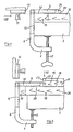
- FIG. 7 shows a section in the area of a slot 8 of the back plate, which has a trapezoidally enlarged passage 27 for the frustoconical end mill 17, cf. also FIG. 8.
- dovetail-shaped grooves 15 are created.
- This contour is adapted to the cross section of the alignment fingers 22, as FIG. 9 shows more precisely.
- the alignment finger 22 has a trapezoidal cross-section, the smaller base 28, in adaptation to the flipped first board 16, lying on the table support surface 29 of the table support plate 5.
- the length 30 of the small trapezoidal base corresponds to the smallest diameter 31 of the truncated cone cutter 17.
- the embodiment of the passage opening 27 and the alignment finger 22 also allow the use of a cylindrical end mill 32 according to FIG. 10, only its diameter 33 having to be equal to the length of the large trapezoidal base 34 of the alignment finger 22.
- FIG. 11 shows a second example of an alignment finger 35 with a rectangular cross-section, which of course is first of all adapted to rectangular grooves of the same width.
- alignment with dotted tail-shaped grooves - or a frustoconical cutter 36 - is also possible if the width of the alignment fingers 35 corresponds to the narrowest width at the opening of this groove.
- the guide part 37 shows a further embodiment of the guide part 37 of an auxiliary device for milling grooves in the case of boards for comb-corner connections which are to be contracted at right angles.
- the guide part 37 consists of a guide plate 38 and an alignment plate 39 arranged at right angles to it.
- the guide plate 38 is, like the table support plate or the back plate of the embodiment according to FIG. 1, provided with comb-like slots 40 which pass through the alignment plate 39.
- the alignment plate 39 itself has no slots, but is provided on its free edge 42 facing away from the corner angle 41 of the plates 38, 39 with two alignment fingers 43 which protrude perpendicularly to the extent of the slots 40 of the guide plate 38.
- the alignment fingers are facing the slots 40 offset so that they lie in alignment with a prong 44 spacing two slots 40.
- the cross section of the alignment fingers 43 is adapted to the contour of a groove 15 to be milled.
- longitudinal grooves 15 can be milled in a first board 16 in a first step analogous to FIG. 4.
- the guide plate 38 is placed on the board 16 and the guide part 37 is clamped to the work table 3 with a screw clamp or the like (not shown).
- transverse grooves 19 can be milled in a second board 18 in a second step.
- the alignment plate 39 is placed on the second board 18, while the guide plate 38 now lies vertically in front of the work table 3 with the slots 40 pointing downward.
- the guide part 37 can be precisely aligned again and then clamped onto the work table 3.
Landscapes
- Life Sciences & Earth Sciences (AREA)
- Engineering & Computer Science (AREA)
- Wood Science & Technology (AREA)
- Mechanical Engineering (AREA)
- Forests & Forestry (AREA)
- Dovetailed Work, And Nailing Machines And Stapling Machines For Wood (AREA)
- Polishing Bodies And Polishing Tools (AREA)
- Joining Of Corner Units Of Frames Or Wings (AREA)
Claims (8)
Priority Applications (1)
| Application Number | Priority Date | Filing Date | Title |
|---|---|---|---|
| AT85114264T ATE33580T1 (de) | 1984-11-09 | 1985-11-08 | Hilfsvorrichtung zum fraesen von nuten bei rechtwinklig zusammenzuzinkenden brettern. |
Applications Claiming Priority (2)
| Application Number | Priority Date | Filing Date | Title |
|---|---|---|---|
| DE19843440945 DE3440945A1 (de) | 1984-11-09 | 1984-11-09 | Hilfsvorrichtung zum fraesen von nuten bei rechtwinklig zusammenzuzinkenden brettern |
| DE3440945 | 1984-11-09 |
Publications (2)
| Publication Number | Publication Date |
|---|---|
| EP0181623A1 EP0181623A1 (fr) | 1986-05-21 |
| EP0181623B1 true EP0181623B1 (fr) | 1988-04-20 |
Family
ID=6249882
Family Applications (1)
| Application Number | Title | Priority Date | Filing Date |
|---|---|---|---|
| EP85114264A Expired EP0181623B1 (fr) | 1984-11-09 | 1985-11-08 | Dispositif auxiliaire pour fraiser des rainures pour assembler des planches à angle droit |
Country Status (4)
| Country | Link |
|---|---|
| US (1) | US4648433A (fr) |
| EP (1) | EP0181623B1 (fr) |
| AT (1) | ATE33580T1 (fr) |
| DE (2) | DE3440945A1 (fr) |
Families Citing this family (20)
| Publication number | Priority date | Publication date | Assignee | Title |
|---|---|---|---|---|
| US4928399A (en) * | 1989-02-09 | 1990-05-29 | Jer's Pattern Project, Inc. | Marking template |
| US5199477A (en) * | 1992-02-13 | 1993-04-06 | Keller David A | Apparatus and method for forming dovetail joints |
| US5421384A (en) * | 1994-01-26 | 1995-06-06 | Nuwordu; Alexander A. | Unlimited width dovetailing system with overhead clamp |
| US5692861A (en) * | 1996-09-12 | 1997-12-02 | Stottmann; Richard L. | Method and device for making dovetail and pin pattern plates |
| US7455089B2 (en) * | 2004-07-30 | 2008-11-25 | Black & Decker Inc. | Jig apparatus |
| US7857020B2 (en) * | 2004-07-30 | 2010-12-28 | Black & Decker Inc. | Jig apparatus |
| US7434604B2 (en) * | 2004-07-30 | 2008-10-14 | Black & Decker Inc. | Jig apparatus |
| GB2422132B (en) * | 2005-01-12 | 2009-07-15 | Derek Quinton | Slot cutting apparatus |
| US7241091B1 (en) * | 2006-06-23 | 2007-07-10 | Kun-Ying Yang | Decoration-used mold unit |
| USD560235S1 (en) | 2006-08-22 | 2008-01-22 | Black & Decker Corporation | Sliding tapered dovetail and fixed half-blind dovetail template |
| USD573615S1 (en) | 2006-08-22 | 2008-07-22 | Black & Decker Inc. | Dust collector |
| USD559875S1 (en) | 2006-08-22 | 2008-01-15 | Black & Decker Corporation | Half-blind router bit depth guide |
| USD569882S1 (en) | 2006-08-22 | 2008-05-27 | Black & Decker Inc. | Miniature variable-spaced finger assembly |
| USD559287S1 (en) | 2006-08-22 | 2008-01-08 | Black & Decker Corporation | Variable-spaced finger assembly |
| USD575312S1 (en) | 2006-08-22 | 2008-08-19 | Black & Decker Inc. | Outrigger for a jig apparatus |
| USD571836S1 (en) | 2006-08-22 | 2008-06-24 | Black & Decker Inc. | Box joint template |
| USD577752S1 (en) | 2006-08-22 | 2008-09-30 | Black & Decker Inc. | Jig apparatus |
| USD574864S1 (en) | 2006-08-22 | 2008-08-12 | Black & Decker Inc | Mortise and tenon assembly |
| US7828024B1 (en) * | 2008-05-07 | 2010-11-09 | General Tool Mfg. Co, LLC | Dovetail jig |
| US20160214425A1 (en) * | 2015-01-22 | 2016-07-28 | Mabel Ko | Writing Template |
Family Cites Families (5)
| Publication number | Priority date | Publication date | Assignee | Title |
|---|---|---|---|---|
| DE1004363B (de) * | 1953-11-06 | 1957-03-14 | Bosch Gmbh Robert | Zusatzeinrichtung fuer elektrische Hand-werkzeugmaschinen mit einem zum Fuehren des zu bearbeitenden Werkstuecks dienenden Auflagetisch |
| US3606916A (en) * | 1969-09-30 | 1971-09-21 | Mildred M Day | Gauge apparatus and method for cutting uniformly spaced routered tenons and mortises |
| DE2524247A1 (de) * | 1975-05-31 | 1976-12-09 | Robert Wolff | Fraeslehre fuer das fraesen der schwalbenschwanznuten bei rechtwinklig zusammenzuzinkenden brettern |
| DE2642924C3 (de) * | 1976-09-24 | 1980-02-07 | Robert 5446 Engeln Wolff | Hilfsvorrichtung zum Fräsen von Schwalbenschwanznuten bei rechtwinklig zusammenzuzinkenden Brettern |
| IT1075361B (it) * | 1976-05-15 | 1985-04-22 | Wolff Robert | Maschera per fresare incavi a coda di rondine in tavole da congiungere con incastro ortogonlae |
-
1984
- 1984-11-09 DE DE19843440945 patent/DE3440945A1/de not_active Withdrawn
-
1985
- 1985-11-08 EP EP85114264A patent/EP0181623B1/fr not_active Expired
- 1985-11-08 DE DE8585114264T patent/DE3562198D1/de not_active Expired
- 1985-11-08 AT AT85114264T patent/ATE33580T1/de active
- 1985-11-12 US US06/796,809 patent/US4648433A/en not_active Expired - Fee Related
Also Published As
| Publication number | Publication date |
|---|---|
| ATE33580T1 (de) | 1988-05-15 |
| DE3440945A1 (de) | 1986-05-15 |
| DE3562198D1 (en) | 1988-05-26 |
| EP0181623A1 (fr) | 1986-05-21 |
| US4648433A (en) | 1987-03-10 |
Similar Documents
| Publication | Publication Date | Title |
|---|---|---|
| EP0181623B1 (fr) | Dispositif auxiliaire pour fraiser des rainures pour assembler des planches à angle droit | |
| DE69512488T2 (de) | Keilzinkenschablone | |
| DE3343683A1 (de) | Bohr- und fraesfuehrer fuer auswechselbare antriebsmaschinen | |
| EP0149429B1 (fr) | Dispositif pour maintenir une pièce dans une position spatiale désirée | |
| EP0584729A1 (fr) | Dispositif de perçage pour trous de chevilles | |
| EP0320869A2 (fr) | Dispositif auxiliaire pour fraiser les queues-d'aronde | |
| DE3430496C2 (de) | Hilfsvorrichtung zum Fräsen von Schwalbenschwanznuten bei rechtwinklig zusammenzuzinkenden Brettern | |
| DE4216338C2 (de) | Schutzhaube für Holzfräsmaschinen | |
| DE4016834A1 (de) | Fraeslehre zum fraesen von zinken | |
| DE19844516A1 (de) | Tragbare Vorrichtung zur Erstellung von Dübellöchern und/oder Ausfräsungen | |
| DE9016090U1 (de) | Vorrichtung zum Zwangsführen eines Gerätes | |
| DE2808276C2 (de) | Holzbearbeitungsmaschine zum Zapfenschlagen und Längsprofilieren | |
| DE3706832C2 (de) | Führungssystem für Elektrowerkzeuge | |
| EP0118077B1 (fr) | Butée à onglets | |
| DE3105181A1 (de) | Schneidwerkzeug | |
| EP0160264A1 (fr) | Outil de marquage | |
| DE2642924C3 (de) | Hilfsvorrichtung zum Fräsen von Schwalbenschwanznuten bei rechtwinklig zusammenzuzinkenden Brettern | |
| DE2544097A1 (de) | Schraubstockbacken fuer werkzeugmaschinen | |
| DE2059558C3 (de) | Verstellbarer Endanschlag | |
| DE2524247A1 (de) | Fraeslehre fuer das fraesen der schwalbenschwanznuten bei rechtwinklig zusammenzuzinkenden brettern | |
| DE1453193B2 (de) | Führungseinrichtung für abzurichtende krummgesägte oder windschief verzogene Werkstücke aus Holz oder ähnlichem Werkstoff | |
| DE4404967C1 (de) | Längsanschlag für eine Holzfräsmaschine | |
| DE9211151U1 (de) | Radiusfräsvorrichtung, insbesondere zum Fräsen von kreisbogenförmigen Nuten in Holz | |
| EP0666133B1 (fr) | Guidage longitudinal pour fraiseuses à bois | |
| DE1800469C3 (de) | Vorrichtung zum Fräsen von Keil zinken |
Legal Events
| Date | Code | Title | Description |
|---|---|---|---|
| PUAI | Public reference made under article 153(3) epc to a published international application that has entered the european phase |
Free format text: ORIGINAL CODE: 0009012 |
|
| AK | Designated contracting states |
Kind code of ref document: A1 Designated state(s): AT BE CH DE FR GB LI NL |
|
| 17P | Request for examination filed |
Effective date: 19860502 |
|
| 17Q | First examination report despatched |
Effective date: 19871007 |
|
| GRAA | (expected) grant |
Free format text: ORIGINAL CODE: 0009210 |
|
| AK | Designated contracting states |
Kind code of ref document: B1 Designated state(s): AT BE CH DE FR GB LI NL |
|
| REF | Corresponds to: |
Ref document number: 33580 Country of ref document: AT Date of ref document: 19880515 Kind code of ref document: T |
|
| REF | Corresponds to: |
Ref document number: 3562198 Country of ref document: DE Date of ref document: 19880526 |
|
| GBT | Gb: translation of ep patent filed (gb section 77(6)(a)/1977) | ||
| ET | Fr: translation filed | ||
| PLBE | No opposition filed within time limit |
Free format text: ORIGINAL CODE: 0009261 |
|
| STAA | Information on the status of an ep patent application or granted ep patent |
Free format text: STATUS: NO OPPOSITION FILED WITHIN TIME LIMIT |
|
| 26N | No opposition filed | ||
| PGFP | Annual fee paid to national office [announced via postgrant information from national office to epo] |
Ref country code: BE Payment date: 19921007 Year of fee payment: 8 |
|
| PGFP | Annual fee paid to national office [announced via postgrant information from national office to epo] |
Ref country code: GB Payment date: 19921009 Year of fee payment: 8 Ref country code: CH Payment date: 19921009 Year of fee payment: 8 |
|
| PGFP | Annual fee paid to national office [announced via postgrant information from national office to epo] |
Ref country code: FR Payment date: 19921027 Year of fee payment: 8 |
|
| PGFP | Annual fee paid to national office [announced via postgrant information from national office to epo] |
Ref country code: AT Payment date: 19921028 Year of fee payment: 8 |
|
| PGFP | Annual fee paid to national office [announced via postgrant information from national office to epo] |
Ref country code: DE Payment date: 19921111 Year of fee payment: 8 |
|
| PGFP | Annual fee paid to national office [announced via postgrant information from national office to epo] |
Ref country code: NL Payment date: 19921130 Year of fee payment: 8 |
|
| PG25 | Lapsed in a contracting state [announced via postgrant information from national office to epo] |
Ref country code: GB Effective date: 19931108 Ref country code: AT Effective date: 19931108 |
|
| PG25 | Lapsed in a contracting state [announced via postgrant information from national office to epo] |
Ref country code: LI Effective date: 19931130 Ref country code: CH Effective date: 19931130 Ref country code: BE Effective date: 19931130 |
|
| BERE | Be: lapsed |
Owner name: WOLFF ROBERT Effective date: 19931130 |
|
| PG25 | Lapsed in a contracting state [announced via postgrant information from national office to epo] |
Ref country code: NL Effective date: 19940601 |
|
| GBPC | Gb: european patent ceased through non-payment of renewal fee |
Effective date: 19931108 |
|
| NLV4 | Nl: lapsed or anulled due to non-payment of the annual fee | ||
| PG25 | Lapsed in a contracting state [announced via postgrant information from national office to epo] |
Ref country code: FR Effective date: 19940729 |
|
| REG | Reference to a national code |
Ref country code: CH Ref legal event code: PL |
|
| PG25 | Lapsed in a contracting state [announced via postgrant information from national office to epo] |
Ref country code: DE Effective date: 19940802 |
|
| REG | Reference to a national code |
Ref country code: FR Ref legal event code: ST |