EP0181645B1 - Chambre de combustion pour moteur à combustion interne - Google Patents
Chambre de combustion pour moteur à combustion interne Download PDFInfo
- Publication number
- EP0181645B1 EP0181645B1 EP85114542A EP85114542A EP0181645B1 EP 0181645 B1 EP0181645 B1 EP 0181645B1 EP 85114542 A EP85114542 A EP 85114542A EP 85114542 A EP85114542 A EP 85114542A EP 0181645 B1 EP0181645 B1 EP 0181645B1
- Authority
- EP
- European Patent Office
- Prior art keywords
- combustion chamber
- cavity
- exhaust valve
- chamber structure
- piston
- Prior art date
- Legal status (The legal status is an assumption and is not a legal conclusion. Google has not performed a legal analysis and makes no representation as to the accuracy of the status listed.)
- Expired - Lifetime
Links
- 238000002485 combustion reaction Methods 0.000 title claims description 52
- 239000000446 fuel Substances 0.000 claims description 28
- 238000002347 injection Methods 0.000 claims description 28
- 239000007924 injection Substances 0.000 claims description 28
- 239000007921 spray Substances 0.000 claims description 12
- 238000011144 upstream manufacturing Methods 0.000 claims 1
- 238000009736 wetting Methods 0.000 claims 1
- 239000007789 gas Substances 0.000 description 16
- 239000004071 soot Substances 0.000 description 6
- 230000003247 decreasing effect Effects 0.000 description 5
- 229930195733 hydrocarbon Natural products 0.000 description 4
- 150000002430 hydrocarbons Chemical class 0.000 description 4
- 230000006835 compression Effects 0.000 description 2
- 238000007906 compression Methods 0.000 description 2
- 238000010586 diagram Methods 0.000 description 2
- 238000003754 machining Methods 0.000 description 2
- QVGXLLKOCUKJST-UHFFFAOYSA-N atomic oxygen Chemical compound [O] QVGXLLKOCUKJST-UHFFFAOYSA-N 0.000 description 1
- 238000007796 conventional method Methods 0.000 description 1
- 230000014759 maintenance of location Effects 0.000 description 1
- 239000001301 oxygen Substances 0.000 description 1
- 229910052760 oxygen Inorganic materials 0.000 description 1
Images


Classifications
-
- F—MECHANICAL ENGINEERING; LIGHTING; HEATING; WEAPONS; BLASTING
- F02—COMBUSTION ENGINES; HOT-GAS OR COMBUSTION-PRODUCT ENGINE PLANTS
- F02B—INTERNAL-COMBUSTION PISTON ENGINES; COMBUSTION ENGINES IN GENERAL
- F02B23/00—Other engines characterised by special shape or construction of combustion chambers to improve operation
- F02B23/02—Other engines characterised by special shape or construction of combustion chambers to improve operation with compression ignition
- F02B23/06—Other engines characterised by special shape or construction of combustion chambers to improve operation with compression ignition the combustion space being arranged in working piston
- F02B23/0645—Details related to the fuel injector or the fuel spray
- F02B23/066—Details related to the fuel injector or the fuel spray the injector being located substantially off-set from the cylinder centre axis
-
- F—MECHANICAL ENGINEERING; LIGHTING; HEATING; WEAPONS; BLASTING
- F02—COMBUSTION ENGINES; HOT-GAS OR COMBUSTION-PRODUCT ENGINE PLANTS
- F02B—INTERNAL-COMBUSTION PISTON ENGINES; COMBUSTION ENGINES IN GENERAL
- F02B23/00—Other engines characterised by special shape or construction of combustion chambers to improve operation
- F02B23/02—Other engines characterised by special shape or construction of combustion chambers to improve operation with compression ignition
- F02B23/06—Other engines characterised by special shape or construction of combustion chambers to improve operation with compression ignition the combustion space being arranged in working piston
- F02B23/0618—Other engines characterised by special shape or construction of combustion chambers to improve operation with compression ignition the combustion space being arranged in working piston having in-cylinder means to influence the charge motion
- F02B23/0624—Swirl flow
-
- F—MECHANICAL ENGINEERING; LIGHTING; HEATING; WEAPONS; BLASTING
- F02—COMBUSTION ENGINES; HOT-GAS OR COMBUSTION-PRODUCT ENGINE PLANTS
- F02B—INTERNAL-COMBUSTION PISTON ENGINES; COMBUSTION ENGINES IN GENERAL
- F02B23/00—Other engines characterised by special shape or construction of combustion chambers to improve operation
- F02B23/02—Other engines characterised by special shape or construction of combustion chambers to improve operation with compression ignition
- F02B23/06—Other engines characterised by special shape or construction of combustion chambers to improve operation with compression ignition the combustion space being arranged in working piston
- F02B23/0675—Other engines characterised by special shape or construction of combustion chambers to improve operation with compression ignition the combustion space being arranged in working piston the combustion space being substantially spherical, hemispherical, ellipsoid or parabolic
-
- F—MECHANICAL ENGINEERING; LIGHTING; HEATING; WEAPONS; BLASTING
- F02—COMBUSTION ENGINES; HOT-GAS OR COMBUSTION-PRODUCT ENGINE PLANTS
- F02B—INTERNAL-COMBUSTION PISTON ENGINES; COMBUSTION ENGINES IN GENERAL
- F02B2275/00—Other engines, components or details, not provided for in other groups of this subclass
- F02B2275/14—Direct injection into combustion chamber
-
- F—MECHANICAL ENGINEERING; LIGHTING; HEATING; WEAPONS; BLASTING
- F02—COMBUSTION ENGINES; HOT-GAS OR COMBUSTION-PRODUCT ENGINE PLANTS
- F02B—INTERNAL-COMBUSTION PISTON ENGINES; COMBUSTION ENGINES IN GENERAL
- F02B2275/00—Other engines, components or details, not provided for in other groups of this subclass
- F02B2275/40—Squish effect
-
- F—MECHANICAL ENGINEERING; LIGHTING; HEATING; WEAPONS; BLASTING
- F02—COMBUSTION ENGINES; HOT-GAS OR COMBUSTION-PRODUCT ENGINE PLANTS
- F02B—INTERNAL-COMBUSTION PISTON ENGINES; COMBUSTION ENGINES IN GENERAL
- F02B3/00—Engines characterised by air compression and subsequent fuel addition
- F02B3/06—Engines characterised by air compression and subsequent fuel addition with compression ignition
-
- Y—GENERAL TAGGING OF NEW TECHNOLOGICAL DEVELOPMENTS; GENERAL TAGGING OF CROSS-SECTIONAL TECHNOLOGIES SPANNING OVER SEVERAL SECTIONS OF THE IPC; TECHNICAL SUBJECTS COVERED BY FORMER USPC CROSS-REFERENCE ART COLLECTIONS [XRACs] AND DIGESTS
- Y02—TECHNOLOGIES OR APPLICATIONS FOR MITIGATION OR ADAPTATION AGAINST CLIMATE CHANGE
- Y02T—CLIMATE CHANGE MITIGATION TECHNOLOGIES RELATED TO TRANSPORTATION
- Y02T10/00—Road transport of goods or passengers
- Y02T10/10—Internal combustion engine [ICE] based vehicles
- Y02T10/12—Improving ICE efficiencies
Definitions
- This invention relates to a combustion chamber structure in a direct injection type internal combustion engine according to the preamble of the main claim.
- Engines of this type are disclosed in GB-A 1 172 455, DE-A 32 14 096 and CH-A 335 297.
- a substantially spherical cavity is formed in an upper surface of each piston.
- the opening of the cavity is made smaller in area than the bottom of the cavity, to increase the speed of a swirl stream therein, and to positively utilize a squishing action to improve combustion efficiency.
- the cavity opening be reduced in area, and that the injection position be as far from the cavity center as possible but not so far that the spray strikes the wall of the cavity.
- the cavity opening has a spray relief.
- the space above the piston should be made small in order to maximize the cavity volume and the compression ratio; however, machining accuracy limits the amount that this space may be reduced. If, however, in a direct injection type internal combustion engine, this space is decreased in size, the exhaust valve and the piston may interfere with each other, so that valve stamping may occur during operation.
- the fuel spray from a fuel injection nozzle is caused to strike against the wall of the combustion chamber thereby to form a fuel film on the wall, or that, in an engine in which the cavity opening is not reduced in area, the unburned or partly-burned gas leaks onto the upper surface of the piston and is cooled there, so that the combustion is stopped, thus forming soot and hydrocarbons.
- an object of this invention is to provide a combustion chamber structure in an internal combustion engine in which combustion of unburned or partially- burned gas which leaks out to the cavity in the upper surface of the piston is positively accelerated, thereby reducing the amount of soot and hydrocarbons in the exhaust gas, improving combustion efficiency, and providing high power.
- the invention is especially useful for direct injection type internal combustion engines using single-hole type injection nozzles.
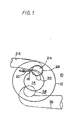
- a generally spherical cavity 14 is formed in the upper surface of a piston 12 which is moved up and down within a cylinder block 10.
- the cavity 14 has a spray relief 16 which partially increases the opening area of the cavity 14 as viewed along an axis of the piston 12, and is faced by a fuel injection valve 20 which is secured to a cylinder head 18.
- the fuel injection valve 20 is so designed that it can spray fuel 22 from its single injection hole through the spray relief 16 into the cavity 14 in such a manner that the fuel spray goes along the swirl stream in the cavity 14.
- a recess 24 is formed adjacent to the cavity 14, thus providing an auxiliary combustion chamber.
- an exhaust valve 28 for opening and closing an exhaust port 26 in an exhaust system is provided in the cylinder head 18, in such a manner that it is shifted in the direction of enlargement of the combustion chamber (upwardly in Fig. 4) rather than towards the lower surface of the cylinder head 18 thus forming an auxiliary combustion chamber 30 in a manner similar to the recess 24.
- the auxiliary combustion chamber 30 has a cut 32 which is wider towards the exhaust valve 28 from the cavity 14, and is used for guiding leaked gas.
- a cut 34 is formed in the bottom surface of the exhaust valve 28 in such a manner that the cut 34 is aligned with the aforementioned cut 32 while its width and depth are gradually increased, from the side adjacent to the cut 32 towards its other end.
- the exhaust valve 28 is disposed in such a manner that it partially overlaps the cavity 14 as viewed along an axis of the piston 12.
- the exhaust valve 28 also overlies the recess 24 forming the one auxiliary combustion chamber provided on one side of the cavity 14 such that on the opposite side of the recess 24 the exhaust valve is provided.
- the intake valve 38 is adapted to open and close the intake port 36 which is a part of the suction system and forms the swirling air stream in the combustion chamber.
- the fuel injection valve 20 jets fuel 22 into the cavity 14. At the same time, the air is compressed and the gas temperature in the combustion chamber is increased, as a result of which the fuel 22 thus jetted is ignited, combusted, and exploded.
- the piston 12 is moved downwardly during combustion, burned and unburned gas begins to leak onto the upper surface of the piston from the cavity 14.
- the exhaust valve 28 is located near the cavity 14, so that the gas streaming from the cavity 14 to the exhaust valve 28 is maintained hot by the high temperature exhaust valve 28 and its atmospheric temperature. Therefore, combustion is complete, and the unburned gas, having its combustion accelerated, is discharged through the exhaust port 26. Combustion is further accelerated by means of the recess 24 and the auxiliary chamber 30.
- combustion efficiency is improved, and valve stamping by the exhaust valve 28 or the piston 12 is prevented, so that the space may be provided with a lower accuracy. Therefore, assembly is easier, and the machining cost is relatively low.
- the space is the same as in the conventional structure, then the volume ratio of the piston 12 can be large, the air utilization factor is increased, and the combustion in the top clearance is carried out mainly in the auxiliary combustion chamber 30 and collectively in the recess 24. Therefore, oxygen is supplied to the recess 24 and the auxiliary combustion chamber 30 with the aid of the swirl stream therein, and the air utilization factor is further increased. In this case, the compression ratio is scarcely decreased, so that the starting characteristic is maintained substantially unchanged, and engine performance is scarcely lowered during warm-up.
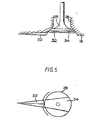
- reference character A designates a point where the fuel 22 strikes the wall of the cavity 14; L i , a line connecting the center 0 of the cavity 14 and the point A as viewed along an axis of the piston 12; and L 2 , a line extending radially from the cavity center O in such a manner that the line L 2 is downstream of the swirl stream and forms an angle of 130° with the line L 1 .
- L i a line connecting the center 0 of the cavity 14 and the point A as viewed along an axis of the piston 12
- L 2 a line extending radially from the cavity center O in such a manner that the line L 2 is downstream of the swirl stream and forms an angle of 130° with the line L 1 .
- the cavity 14 has no recess 16, and the fuel 22 from the fuel injection valve 20 strikes the wall of the cavity 14, it is preferable that, when the rated speed is about 4,000 rpm, the exhaust valve be positioned in a range of about 130° from the position -where the exhaust valve contacts the line L 1 from the downstream side of the swirl stream, which extends, as shown in the Figure, to the position where the exhaust valve contacts the line L 2 from the downstream side of the swirl stream.
- the exhaust valve 28 is positioned in a range of about 30° from the position where the exhaust valve contacts a line L 3 from the downstream side of the swirl stream, which extends, as shown in the Figure, to the position where the exhaust valve contacts a line L 4 from the downstream side of the swirl stream.
- the line L 3 connects the center O of the cavity 14 and the fuel injection hole of the fuel injection valve 20.
- the line L 4 is extended from the center O of the cavity 14 and forms an angle of 30° with the line L 3 .
- the cavity 14 has a recess 16, and the fuel 22 from the fuel injection valve 20 does not strike the wall of the cavity 14, similarly as in the case of the above- described engine, it is desirable that the exhaust valve is positioned in a range of about 30° downstream of the fuel injection hole of the fuel injection valve 20.
Landscapes
- Engineering & Computer Science (AREA)
- Chemical & Material Sciences (AREA)
- Combustion & Propulsion (AREA)
- Mechanical Engineering (AREA)
- General Engineering & Computer Science (AREA)
- Combustion Methods Of Internal-Combustion Engines (AREA)
Claims (8)
Applications Claiming Priority (2)
| Application Number | Priority Date | Filing Date | Title |
|---|---|---|---|
| JP59241535A JPS61118523A (ja) | 1984-11-15 | 1984-11-15 | 内燃機関用燃焼室構造 |
| JP241535/84 | 1984-11-15 |
Publications (2)
| Publication Number | Publication Date |
|---|---|
| EP0181645A1 EP0181645A1 (fr) | 1986-05-21 |
| EP0181645B1 true EP0181645B1 (fr) | 1991-01-23 |
Family
ID=17075792
Family Applications (1)
| Application Number | Title | Priority Date | Filing Date |
|---|---|---|---|
| EP85114542A Expired - Lifetime EP0181645B1 (fr) | 1984-11-15 | 1985-11-15 | Chambre de combustion pour moteur à combustion interne |
Country Status (3)
| Country | Link |
|---|---|
| EP (1) | EP0181645B1 (fr) |
| JP (1) | JPS61118523A (fr) |
| DE (1) | DE3581493D1 (fr) |
Cited By (1)
| Publication number | Priority date | Publication date | Assignee | Title |
|---|---|---|---|---|
| DE102009020420A1 (de) * | 2009-05-08 | 2010-11-11 | Volkswagen Ag | Brennkraftmaschine mit Direkteinspritzung |
Family Cites Families (4)
| Publication number | Priority date | Publication date | Assignee | Title |
|---|---|---|---|---|
| CH335297A (de) * | 1955-03-14 | 1958-12-31 | Lanova Ag | Brennstoff-Einspritzverfahren für Brennkraftmaschinen |
| DE1451636A1 (de) * | 1963-09-21 | 1969-07-10 | Daimler Benz Ag | Dieselmotor,insbesondere Viertaktmotor fuer Kraftfahrzeuge |
| GB1172455A (en) * | 1966-05-25 | 1969-12-03 | Ustav Pro Vyzkum Motorovych Vo | Improvements in or relating to internal combustion engines |
| JPS57171026A (en) * | 1981-04-16 | 1982-10-21 | Nippon Soken Inc | Direct injection type diesel engine |
-
1984
- 1984-11-15 JP JP59241535A patent/JPS61118523A/ja active Pending
-
1985
- 1985-11-15 DE DE8585114542T patent/DE3581493D1/de not_active Expired - Lifetime
- 1985-11-15 EP EP85114542A patent/EP0181645B1/fr not_active Expired - Lifetime
Cited By (1)
| Publication number | Priority date | Publication date | Assignee | Title |
|---|---|---|---|---|
| DE102009020420A1 (de) * | 2009-05-08 | 2010-11-11 | Volkswagen Ag | Brennkraftmaschine mit Direkteinspritzung |
Also Published As
| Publication number | Publication date |
|---|---|
| EP0181645A1 (fr) | 1986-05-21 |
| DE3581493D1 (de) | 1991-02-28 |
| JPS61118523A (ja) | 1986-06-05 |
Similar Documents
| Publication | Publication Date | Title |
|---|---|---|
| US4289094A (en) | Two-stroke cycle gasoline engine | |
| US4211189A (en) | Internal combustion engine with dual induction system and more particularly to combustion chamber design thereof | |
| US4359027A (en) | Two-cycle internal combustion engine having high swirl combustion chamber | |
| US4951642A (en) | Combustion chamber of internal combustion engine | |
| US4178903A (en) | Internal combustion engine with an auxiliary combustion chamber | |
| US4545344A (en) | Diesel engine having turbulent combustion chamber | |
| US4344407A (en) | Cylinder head, ports, and piston configuration | |
| CA1206826A (fr) | Moteur a combustion interne avec allumage par flamme | |
| EP0181645B1 (fr) | Chambre de combustion pour moteur à combustion interne | |
| US6701883B2 (en) | Cylinder head for use on a spark-ignition internal combustion engine and such spark-ignition internal combustion engine | |
| US5054441A (en) | Decompression device in a two-cycle engine | |
| JPS5823219A (ja) | 火花点火式内燃機関 | |
| JPH0147606B2 (fr) | ||
| US4254750A (en) | Internal combustion engine with an auxiliary combustion chamber | |
| JPH07116945B2 (ja) | 火花点火式エンジンの燃焼室 | |
| KR100365113B1 (ko) | 직접분사식가솔린기관의피스톤헤드형상구조 | |
| JP2717960B2 (ja) | エンジンの燃焼室 | |
| KR100365114B1 (ko) | 직접분사식가솔린기관의피스톤헤드형상구조 | |
| JPH0545789Y2 (fr) | ||
| JPS6023463Y2 (ja) | デイ−ゼルエンジンの燃料噴射ノズル装置 | |
| KR100227389B1 (ko) | 엔진의 연소실 구조 | |
| KR200174503Y1 (ko) | 내연기관의 연소실 구조 | |
| JPS5926772B2 (ja) | 副室式内燃機関 | |
| JPS6316123A (ja) | 内燃機関 | |
| JPH02305319A (ja) | エンジンの燃焼室構造 |
Legal Events
| Date | Code | Title | Description |
|---|---|---|---|
| PUAI | Public reference made under article 153(3) epc to a published international application that has entered the european phase |
Free format text: ORIGINAL CODE: 0009012 |
|
| AK | Designated contracting states |
Kind code of ref document: A1 Designated state(s): DE GB |
|
| 17P | Request for examination filed |
Effective date: 19861017 |
|
| 17Q | First examination report despatched |
Effective date: 19870408 |
|
| GRAA | (expected) grant |
Free format text: ORIGINAL CODE: 0009210 |
|
| AK | Designated contracting states |
Kind code of ref document: B1 Designated state(s): DE GB |
|
| REF | Corresponds to: |
Ref document number: 3581493 Country of ref document: DE Date of ref document: 19910228 |
|
| REG | Reference to a national code |
Ref country code: GB Ref legal event code: 746 |
|
| PLBE | No opposition filed within time limit |
Free format text: ORIGINAL CODE: 0009261 |
|
| STAA | Information on the status of an ep patent application or granted ep patent |
Free format text: STATUS: NO OPPOSITION FILED WITHIN TIME LIMIT |
|
| 26N | No opposition filed | ||
| PGFP | Annual fee paid to national office [announced via postgrant information from national office to epo] |
Ref country code: GB Payment date: 19921103 Year of fee payment: 8 |
|
| PGFP | Annual fee paid to national office [announced via postgrant information from national office to epo] |
Ref country code: DE Payment date: 19921123 Year of fee payment: 8 |
|
| PG25 | Lapsed in a contracting state [announced via postgrant information from national office to epo] |
Ref country code: GB Effective date: 19931115 |
|
| GBPC | Gb: european patent ceased through non-payment of renewal fee |
Effective date: 19931115 |
|
| PG25 | Lapsed in a contracting state [announced via postgrant information from national office to epo] |
Ref country code: DE Effective date: 19940802 |