EP0181661A1 - Absorptionswärmepumpe mit einem eine Rektifiziervorrichtung enthaltenden Austreiber - Google Patents
Absorptionswärmepumpe mit einem eine Rektifiziervorrichtung enthaltenden Austreiber Download PDFInfo
- Publication number
- EP0181661A1 EP0181661A1 EP85201714A EP85201714A EP0181661A1 EP 0181661 A1 EP0181661 A1 EP 0181661A1 EP 85201714 A EP85201714 A EP 85201714A EP 85201714 A EP85201714 A EP 85201714A EP 0181661 A1 EP0181661 A1 EP 0181661A1
- Authority
- EP
- European Patent Office
- Prior art keywords
- pipe
- holder
- generator
- section
- lamellae
- Prior art date
- Legal status (The legal status is an assumption and is not a legal conclusion. Google has not performed a legal analysis and makes no representation as to the accuracy of the status listed.)
- Withdrawn
Links
Images


Classifications
-
- F—MECHANICAL ENGINEERING; LIGHTING; HEATING; WEAPONS; BLASTING
- F28—HEAT EXCHANGE IN GENERAL
- F28D—HEAT-EXCHANGE APPARATUS, NOT PROVIDED FOR IN ANOTHER SUBCLASS, IN WHICH THE HEAT-EXCHANGE MEDIA DO NOT COME INTO DIRECT CONTACT
- F28D15/00—Heat-exchange apparatus with the intermediate heat-transfer medium in closed tubes passing into or through the conduit walls ; Heat-exchange apparatus employing intermediate heat-transfer medium or bodies
- F28D15/02—Heat-exchange apparatus with the intermediate heat-transfer medium in closed tubes passing into or through the conduit walls ; Heat-exchange apparatus employing intermediate heat-transfer medium or bodies in which the medium condenses and evaporates, e.g. heat pipes
- F28D15/06—Control arrangements therefor
-
- F—MECHANICAL ENGINEERING; LIGHTING; HEATING; WEAPONS; BLASTING
- F25—REFRIGERATION OR COOLING; COMBINED HEATING AND REFRIGERATION SYSTEMS; HEAT PUMP SYSTEMS; MANUFACTURE OR STORAGE OF ICE; LIQUEFACTION SOLIDIFICATION OF GASES
- F25B—REFRIGERATION MACHINES, PLANTS OR SYSTEMS; COMBINED HEATING AND REFRIGERATION SYSTEMS; HEAT PUMP SYSTEMS
- F25B15/00—Sorption machines, plants or systems, operating continuously, e.g. absorption type
- F25B15/02—Sorption machines, plants or systems, operating continuously, e.g. absorption type without inert gas
-
- F—MECHANICAL ENGINEERING; LIGHTING; HEATING; WEAPONS; BLASTING
- F25—REFRIGERATION OR COOLING; COMBINED HEATING AND REFRIGERATION SYSTEMS; HEAT PUMP SYSTEMS; MANUFACTURE OR STORAGE OF ICE; LIQUEFACTION SOLIDIFICATION OF GASES
- F25B—REFRIGERATION MACHINES, PLANTS OR SYSTEMS; COMBINED HEATING AND REFRIGERATION SYSTEMS; HEAT PUMP SYSTEMS
- F25B33/00—Boilers; Analysers; Rectifiers
-
- Y—GENERAL TAGGING OF NEW TECHNOLOGICAL DEVELOPMENTS; GENERAL TAGGING OF CROSS-SECTIONAL TECHNOLOGIES SPANNING OVER SEVERAL SECTIONS OF THE IPC; TECHNICAL SUBJECTS COVERED BY FORMER USPC CROSS-REFERENCE ART COLLECTIONS [XRACs] AND DIGESTS
- Y02—TECHNOLOGIES OR APPLICATIONS FOR MITIGATION OR ADAPTATION AGAINST CLIMATE CHANGE
- Y02A—TECHNOLOGIES FOR ADAPTATION TO CLIMATE CHANGE
- Y02A30/00—Adapting or protecting infrastructure or their operation
- Y02A30/27—Relating to heating, ventilation or air conditioning [HVAC] technologies
-
- Y—GENERAL TAGGING OF NEW TECHNOLOGICAL DEVELOPMENTS; GENERAL TAGGING OF CROSS-SECTIONAL TECHNOLOGIES SPANNING OVER SEVERAL SECTIONS OF THE IPC; TECHNICAL SUBJECTS COVERED BY FORMER USPC CROSS-REFERENCE ART COLLECTIONS [XRACs] AND DIGESTS
- Y02—TECHNOLOGIES OR APPLICATIONS FOR MITIGATION OR ADAPTATION AGAINST CLIMATE CHANGE
- Y02B—CLIMATE CHANGE MITIGATION TECHNOLOGIES RELATED TO BUILDINGS, e.g. HOUSING, HOUSE APPLIANCES OR RELATED END-USER APPLICATIONS
- Y02B30/00—Energy efficient heating, ventilation or air conditioning [HVAC]
- Y02B30/62—Absorption based systems
Definitions
- the invention relates to an absorption heat pump comprising generator and absorber arranged in a first circuit for a solution of work medium and solvent and a condenser and evaporator arranged in a second circuit for the work medium, an outlet of the generator being connected to the condenser and an outlet of the evaporator being connected to the absorber, which is connected via an outlet to an inlet of the generator, while a vertically arranged first metal pipe which extends into a holder of the generator and is closed at its upper end is connected at its lower end to a vessel arranged outside the holder and forming part of the generator, which vessel contains an evaporation and condensation medium, respectively, the space between the holder and the said first pipe being connected to a supply for the solution and to an outlet for gaseous work medium.
- the invention has for its object to provide an absorption heat pump in which the above disadvantages are avoided.
- the invention is for this purpose characterized in that the first pipe is filled in an upper rectifying section with a thermally insulating gas and is wetted with condensing work medium on the inner side of its wall in a lower generating section adjoining the upper section, while the pipe is provided both in the upper and in the lower section with at least one fin which is secured to the outer side of the wall of the pipe and is arranged so as to be clear of the inner side of the wall of the holder.
- the upper part of the first pipe Due to the fact that the upper part of the first pipe is thermally separated from the lower part, the upper part automatically acts as a rectifier while the lower part acts as a generator.
- the integration of rectifier and generator in one pipe body leads to a very simple construction, which can be mass-produced at low cost.
- a preferred embodiment of the absorption heat pump in which also a so-called dephlegmator having constructional features analoguous to those of the rectifier and generator is arranged in the holder, is further characterized in that the holder is provided with a finned second metal pipe which is coaxial with the first pipe, said second pipe being arranged above the first pipe and being closed at its end which faces the first pipe, and said second pipe concentrically surrounding a third pipe which at its open lower end ism communication with a supply for a cooling medium and at its open upper end passes through the closed upper end of the second pipe and is connected to an outlet for the cooling medium, while the space between the holder and the second pipe is connected near the upper end of the holder to the condenser.
- An embodiment of the absorption heat pump having an optimum heat transfer between the condensing medium in the first pipe and the rich solution in the space between the first pipe and the holder is characterized in that the metal fin secured to the first pipe consists of a number of interconnected lamellae which extend helically around the first pipe.
- An embodiment of the absorption heat pump having besides an optimum heat transfer also an optimum mass transfer is further characterized in that the lamellae are provided with capillary passages, the adjacent lamellae of successive turns of the helix partially overlapping each other in the circumferential direction of the first pipe, and the capillary passage located above the surface of an underlying lamella being offset with respect to the capillary passage of said underlying lamella.
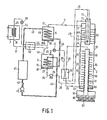
- the preferred embodiment of an absorption heat pump shown in Figure 1 has a first circuit for a solution of work medium and solvent, in which a generator 1 and an absorber 3 are arranged, and a second circuit for the work medium in which a condenser 5 and an evaporator 7 are arranged.
- the solution used is, for example, a mixture of ammonia (work medium) and water (solvent).
- a first outlet 9 of the generator 1 is connected through a conduit 11 to an inlet 13 of the condenser 5, while an outlet 15 of the evaporator 7 is connected via a conduit 17 to a first inlet 19 of the absorber 3.
- the condenser 5 has an outlet 21, which is connected through a conduit 23 to an inlet 25 of the evaporator 7.
- An outlet 27 of the absorber 3 is connected through a series of conduits 29 to an inlet 31 of the generator 1, while a second outlet 33 of the generator 1 is connected through a conduit 35 to a second inlet 37 of the absorber 3.
- the heat pump is provided with a transport conduit 43 for a heating liquid, for example water.
- the water is circulated in the transport conduit 43 by means of a pump 45. Vieqed from the pump 45 in the direction of flow of the water, the latter is successively transported to a heating body 47 for room heating, a heat exchanger 49 arranged in the condenser 5, a heat-mass-exchanger 51 arranged in the absorber and back to the pump 45.
- the conduits 17 and 23 extend in opposite directions of flow through a heat exchanger 53, while the conduits 29 and 35 extend in opposite directions of flow thorugh a heat exchanger 55.
- the generator 1 has a vertically arranged circular-cylindrical holder 57, in which a first metal pipe 59 of circular cross-section is coaxially arranged.
- the first pipe 59 is closed at its upper end and passes near its lower end through the bottom of the holder 57 to the outside.
- a vessel 61 is connected to the lower end of the first pipe 59.
- a has burner 63 is connected to the first pipe 59.
- a metal fin which consists of a number of interconnected rectangular lamellae 65 extending helically around the first pipe 59 the individual lamellae projecting radially from the pipe.
- the adjacent lamellae 65 of successive turns of the helix partially overlap each other in the circumferential (tangential) direction of the first pipe 59 (see also Figures 2 and 3).
- Each of the lamellae 65 is provided with a capillary passage 67, the passage located above the surface of an underlying lamella being offset with respect to the passage of the underlying lamella.
- the holder 57 is provided with a finned second metal pipe 69 of circular cross section which is coaxial with the first pipe 59, said second pipe 69 being arranged above the first pipe 59 and being closed at its lower end which faces the first pipe 59.
- the second metal pipe 69 concentrically surrounds a third pipe 71 of circular cross-section which at its open lower end is in communication with a supply 73 for a cooling medium (solution) and at its end passes through the closed upper end of the second metal pipe 69 and is connected to an outlet 75 for the cooling medium, which outlet is connected to the conduit 29.
- the second pipe 69 passes through the closed upper end of the holder 57.
- the third pipe 71 is thermally insulated or made of a thermally insulating material (not shown).
- a metal fin which consists of a number of interconnected rectangular lamellae 77 extending helically around the second pipe 69.
- the helical fin constituted by the lamellae 77 is preferably pressed bodily into the space between the holder 57 and the second pile 69, the inner edge of the fin engaging the outer surface of the second pipe 69 and the outer edge of the fin engaging the inner surface of the holder 57.
- the lamellae 65 of the fin wound around the first pipe 59 are arranged so as to be completely clear of the inner surface of the holder 57.
- the lamellae configuration of the fin wound around the second pipe 69 is entirely identical to that of the fin wound around the first pipe 59 except for the fact that the lamellae 77 of the fin wound around the second pipe 69 do not possess capillary passages. However, this may be the case if the mass pair used provides a reason for it.
- the holder 57 has three sections, namely: a first section 79, which acts as a generator, a section 8; which acts as a rectifier, and a section 83 which acts as a so-called dephlegmator.
- a first section 79 which acts as a generator
- a section 8 which acts as a rectifier
- a section 83 which acts as a so-called dephlegmator.
- the combination of the three sections 79, 81 and 83 is designated as a generator 1.
- the generator 1 consequently is a generator in which a rectifier and a dephlegmator are integrated.
- the third section 83 acting as dephlegmator is to be preferred, in a number of cases this section mays also be dispensed with.
- the vessel 61 contains a liquid evaporation and condensation medium 85, such as, for example, water.
- a quantity of non-condensing gas 87 Into the upper part of the first pipe 59 is introduced a quantity of non-condensing gas 87, by which the rectifier action of the section 81 is through about.
- the gas 87 may be, for example, nitrogen gas.
- the water vapour ascends in the first pipe 59 and forms on the comparatively cold inner surface of the wall of this pipe a condensate film 91 which extends as far as the rectifier section 81.
- thermo-siphon a particular form of a heat pipe.
- heat is transferred with the aid of the condensate film 91 in the generator section 79 to the lamellae 65.
- a film 93 (see Figure 3, 4 and 5) of an initially comparatively cold rich solution of ammonia and water is present on these lamellae 65. This solution flows into the generator via the inlet 31 and originates from the absorber 3.
- a comparatively cold rich solution 97 in the absorber 3 is continuously pumped to the generator 1 via the series of circuits 29.
- this solution reaches the dephlegmator section 83 and is then conducted via the third pipe 71, which forms part of the series of conduits 29, to the heat exchanger 55 and is there already preheated by comparatively hot poor solution flowing in the conduit 35.
- the preheated rich solution entering the holder 57 via the inlet 31 falls first on the lamellae 65 of the rectifier section 81, then on the lamellae 65 of the generator section 79 and is collected in an impoverished state in the lower part of the holder 57 as a comparatively hot poor solution 89.
- the operation of the generator section 79 is now first described, after which the operation of the rectifier section 81 and of the dephlegmator section 83 is described.
- each of the lamellae 65 Due to the comparatively cold rich solution flowing downwards, the aforementioned film 93 is formed on each of the lamellae 65, which film is effectively composed of a comparatively hot lower layer 97 and a cold upper layer 99 (see Figure 5). Viewed over the thickness of the liquid film 93 on the lamellae 65, the temperature increases, as is indicated by an arrow 101.
- the lamellae 65 are directed slightly downwards at their free ends (radial direction) in order to prevent an excess quantity of solution flowing along the outer side of the wall of the first pipe 59. Due to the helical arrangement of the lamellae 65, each lamella is also directed slightly downwards at a longitudinal edge (tangential direction). This orientation of the lamellae 65 is clearly visible in Figures 3 to 5.
- falling drops 103 which are indicated with reference to four lamellae 65 in Figure 3 at different stages.
- the drops 103 fall each time on the film 93 of an underlying lamella 65 beside the capillary passage 67 of the underlying lamella. In Figure 3, this is indicated with a drop 105 on the lowermost lamella 65. Due to the falling drops 103, an intensive mixing is obtained of the richer comparatively cold upper layer 99 in the film 93 with the already impoverished comparatively how lower layer 97 so that the temperature increases uniformly throughout the thickness of the film 93 and the concentration of work medium in the film 93 is distributed homogeneously. Thus, a largest possible quantity of ammonia gas is released from the solution flowing downwards.
- drops 107 are formed, which fall on the film 93 on the subjacent lamellae.
- already formed hot ammonia gas ascending in the holder 57 flows around these drops, as a result of which an additional quantity of ammonia gas is released from the falling drops.
- the rectifier section 81 the ascending hot ammonia gas comes into contact with the still comparatively cold film on the lamellae 65 of this section and the drops falling downwards in this section. As a result, not only an additional quantity of ammonia gas is released, but also the water vapour still present in the ammonia gas is condensed for a considerable part.
- the condensed water is collected in the lower part of the holder 57 and is mixed there with the impoversihed solution 89.
- the rectifier section is substantially adiabatic because no heat is supplied or dissipated from the outside.
- the holder 57 is enveloped for this purpose in an insulating sheath (non shown in Figure 1).
- the nitrogen gas 87 in the rectifier section 81 has the same pressure as the water vapour in the upper part of the generator section 79.
- the water vapour in the upper part of the generator section 79 is separated comparatively clearly from the nitrogen gas in the rectifier section 81.
- the nitrogen gas 87 behaves like an insulator so that the section 81 actually operates automatically as a rectifier )adiabatic).
- a non-condensable gas having a comparatively small diffusion coefficient is used in the rectifier section 81 to minimize heat and mass diffusion on the transitional region between vapour and inert gas and to cause a smallest possible transitional region to be formed.
- a large transitional region in fact decreases the condensation temperature and hence also the heat transfer in the generator section 79, while at the same time a smaller part of the section 81 acts as an adiabatic rectifier.
- the rectangular lamellae 65 have a length of 30 mm, a width of 9 mm and a thickness of, for example, 1 mm.
- the average diameters of the pipe 59 and the holder 57 are 60 mm and 125 mm, respectively, while the wall thicknesses are 2.5 mm and 2.5 mm.
- the vertical distance between two adjacent lamellae is about 9 mm.
- the capillary passages 67 are situated approximately centrally (tangential direction) in the outer part (radial direction) of the lamellae 65 and have a diameter of 2 mm.
- the ascending ammonia gas already cooled in the rectifier section 81 is mostly not yet completely free of water vapour. Therefore, the ammonia gas is preferably passed further through a dephlegmator, which in the present case is constituted by the dephlegmator section 83.
- the temperature in the dephlegmator section 83 is lower than the temperature in the rectifier section 81 because the rich solution flowing through the inlet 73 into the second pipe 69 and the third pipe 71 has not yet been preheated in the heat exchanger 55.
- the solution in the dephlegmator section 83 serves as a cooling medium, which extracts heat from the comparatively hot ammonia gas flowing along the lamellae 77.
- the lamellae 65 of the generator section 79 and the rectifier section 81 are arranged so as to be clear of the inner side of the wall of the holder 57 and that the lamellae 77 of the dephlegmator section 83 angage the inner side of the wall of the holder 57.
- the generator section 79 and the rectifier section 81 act as a heat-mass exchanger, while the dephlegmator section 83 acts as a heat exchanger.
- the third pipe 71 in the dephlegmator section 83 is constructed as a thermally insulated pipe (not shown in Figure 1).
- the hot ammonia gas substantially completely free of water vapour passes via the first outlet 9 of the holder 57 and the conduit 11 to the condenser 5 and is condensed there whilst transferring heat to the heating liquid in the heat exchanger 49.
- the condensor 5 In the lower part of the condensor 5 there is collected a sufficient quantity of ammonia 109, which passes via the outlet 21 and the conduit 23 to the evaporator 7 after having been expanded in the expansion valve 39.
- heat is supplied by means of a heat exchanger 111 to the liquid ammonia, c which consequently evaporates.
- the ammonia gas formed in the evaporator 7 passes via the outlet 15 and the conduit 17 to the first inlet 19 of the absorber 3.
- the comparatively hot liquid ammonia originating from the condensor 5 is already precooled in the beat exchanger 53 by means of the comparatively cold ammonia gas from the evaporator 7.
- the heat released during the absorption process is supplied by means of the heat exchanger 51 to the heating liquid in the transport conduit 43.
- the comparatively hot impoverished solution dissipated via the second outlet 33 from the holder 57 passes through the pipe 35 to the heat exchanger 55 and gives up heat there to the comparatively cold rich solution originating from the absorber 3.
- the impoversihed solution in the pipe 35 is consequently already precooled so that the absorption process can be optimally effected.
- the pressure of the poor solution is reduced, after which this solution is supplied via the second inlet 37 to the absorber.
- the poor solution forms a liquid film on the outer side of the heat exchanger 51 and absorbs the ammonia gas supplied via the first inlet 19.
- the heat-mass exchanger 51 in the absorber 3 may be replaced by a finned pipe of the kind shown in Figure 2. The heat and mass transfer obtained with such a pipe is comparatively high and is based on a mixing process similar to that described with reference to the generator section 79, with the difference that the temperature gradient across the liquid film on a lamella has an opposite direction.
- the nitrogen gas used in the rectifier section 81 may be replaced by other gases, such as, for example, hydrogen gas, argon gas or helium gas,
- the gas used must not be corrosive in relation to the evaporation and condensation medium in the vessel 61 and to the materials of the vessel 61 and of the first pipe 59. Moreover, the gas must not condense at the pressure and temperature prevailing in the pipe 59.
- a gas is preferably used having a comparatively low diffusion coefficient.
- the dephlegmator section 83 described may be dispensed with when a small quantity of water vapour in the ammonia gas is considered acceptable.
- the heating of the vessel 61 may be effected by a gas burner or oil burner. Electrical heating or heating by flue gases is also possible, however.
- a heat exchanger into which flue gases are passed.
- a particular advantage of the invention resides in the fact that similar technologies can be used for the manufacture of the generator, the rectifier and the dephlegmator.
- the manufacture of fins consisting of lamellae can in fact be standardized to a great extent and these fins can be mass-produced in a simple manner and at low cost.
- the invention is described with reference to a finned pipe, in which a substantial drop formation takes place near the free ends and the downwardly directed longitudinal edges of the lamellae, but is not limited thereto.
- the extent to which the said drop formation takes place depends upon a large number of parameters. Important parameters in this connection are:
- lamellae 65 which are provided with capillary passages 67 for an optimum mixing process
- lamellae without capillary passages are adequate. Also in these cases, due to the cascade of lamellae already such a mass exchange is obtained that the absorption heat pump has a comparatively high efficiency.
Landscapes
- Engineering & Computer Science (AREA)
- Physics & Mathematics (AREA)
- Thermal Sciences (AREA)
- Mechanical Engineering (AREA)
- General Engineering & Computer Science (AREA)
- Life Sciences & Earth Sciences (AREA)
- Sustainable Development (AREA)
- Power Engineering (AREA)
- Sorption Type Refrigeration Machines (AREA)
Applications Claiming Priority (2)
| Application Number | Priority Date | Filing Date | Title |
|---|---|---|---|
| NL8403281 | 1984-10-30 | ||
| NL8403281A NL8403281A (nl) | 1984-10-30 | 1984-10-30 | Absorptiewarmtepomp met geintegreerde generator en rectificator. |
Publications (1)
| Publication Number | Publication Date |
|---|---|
| EP0181661A1 true EP0181661A1 (de) | 1986-05-21 |
Family
ID=19844678
Family Applications (1)
| Application Number | Title | Priority Date | Filing Date |
|---|---|---|---|
| EP85201714A Withdrawn EP0181661A1 (de) | 1984-10-30 | 1985-10-21 | Absorptionswärmepumpe mit einem eine Rektifiziervorrichtung enthaltenden Austreiber |
Country Status (3)
| Country | Link |
|---|---|
| US (1) | US4573330A (de) |
| EP (1) | EP0181661A1 (de) |
| NL (1) | NL8403281A (de) |
Cited By (1)
| Publication number | Priority date | Publication date | Assignee | Title |
|---|---|---|---|---|
| FR2695573A1 (fr) * | 1992-09-15 | 1994-03-18 | Pechiney Recherche | Contacteur gaz-liquide à film ruisselant. |
Families Citing this family (19)
| Publication number | Priority date | Publication date | Assignee | Title |
|---|---|---|---|---|
| DE3621993A1 (de) * | 1985-07-02 | 1987-02-12 | Ruhrgas Ag | Absorptions- heiz- oder kuehlvorrichtung |
| US4691528A (en) * | 1985-08-15 | 1987-09-08 | Yazaki Corporation | Air-cooled absorption type water cooling/heating apparatus |
| JP2657809B2 (ja) * | 1987-12-22 | 1997-09-30 | 謙治 岡安 | 熱伝達装置 |
| US4877080A (en) * | 1988-06-13 | 1989-10-31 | Ahlstromforetagen Svenska Ab | Process and apparatus for cooling a fluid |
| US4926659A (en) * | 1989-03-30 | 1990-05-22 | Gas Research Institute | Double effect air conditioning system |
| US5033274A (en) * | 1989-11-28 | 1991-07-23 | Erickson Donald C | Rectification reflux by latent heat exchange with partially depressurized absorbent |
| US5067330A (en) * | 1990-02-09 | 1991-11-26 | Columbia Gas System Service Corporation | Heat transfer apparatus for heat pumps |
| US5205137A (en) * | 1990-09-05 | 1993-04-27 | Hitachi, Ltd. | Absorption air conditioner |
| EP0518833B1 (de) * | 1991-06-13 | 1998-05-13 | Enea Ente Per Le Nuove Tecnologie, L'energia E L'ambiente | Wärmepumpe zum Heizen oder zum Kühlen von Gebäuden und kombiniert damit zur Ausgabe von heissem Wasser für Sanitärvorrichtungen |
| US5771710A (en) * | 1995-03-17 | 1998-06-30 | Gas Research Institute | Thermosyphon cooled absorber for air cooled absorption cycles |
| US5784279A (en) * | 1995-09-29 | 1998-07-21 | Bpm Technology, Inc. | Apparatus for making three-dimensional articles including moving build material reservoir and associated method |
| US5666818A (en) * | 1995-12-26 | 1997-09-16 | Instituto Tecnologico And De Estudios Superiores | Solar driven ammonia-absorption cooling machine |
| KR0177726B1 (ko) * | 1996-06-19 | 1999-04-15 | 구자홍 | 암모니아 지이에이엑스 흡수식 사이클 |
| WO1999024769A1 (en) * | 1997-11-12 | 1999-05-20 | Hitachi, Ltd. | Absorption water heater/chiller and high temperature regenerator therefor |
| US6314752B1 (en) * | 1998-12-18 | 2001-11-13 | The Ohio State University Research Foundation | Mass and heat transfer devices and methods of use |
| US20020048396A1 (en) * | 2000-09-20 | 2002-04-25 | Bewley Wilbur C. | Apparatus and method for three-dimensional scanning of a subject, fabrication of a natural color model therefrom, and the model produced thereby |
| GB0103752D0 (en) * | 2001-02-15 | 2001-04-04 | Vantico Ltd | Three-Dimensional printing |
| IT202100018314A1 (it) * | 2021-07-12 | 2023-01-12 | Milano Politecnico | Deflemmatore per un generatore di vapore refrigerante per macchine termiche ad assorbimento, e relativo generatore comprendente un tale deflemmatore |
| CN117940721A (zh) * | 2021-07-12 | 2024-04-26 | 米兰理工大学 | 用于吸收式热机的冷冻剂蒸气发生器的精馏器以及包含这种精馏器的发生器 |
Citations (12)
| Publication number | Priority date | Publication date | Assignee | Title |
|---|---|---|---|---|
| NL54788C (de) * | 1940-04-06 | |||
| US2281906A (en) * | 1941-03-11 | 1942-05-05 | Socony Vacuum Oil Co Inc | Adiabatic fractionating column |
| US2392894A (en) * | 1944-02-19 | 1946-01-15 | Worthington Pump & Mach Corp | Refrigeration system |
| CA454585A (en) * | 1949-02-15 | Elis Jodell Georg | Storage type water-heating system | |
| US2581347A (en) * | 1943-07-09 | 1952-01-08 | Electrolux Ab | Absorption refrigeration apparatus and heating arrangement therefor |
| LU47960A1 (de) * | 1964-02-14 | 1965-04-12 | ||
| GB1163331A (en) * | 1965-09-30 | 1969-09-04 | David Dalin | Improvements in or relating to Heat Exchangers |
| US3693373A (en) * | 1971-02-22 | 1972-09-26 | Gerald K Gable | Absorption refrigeration machine |
| FR2194932A1 (de) * | 1972-08-02 | 1974-03-01 | Westinghouse Electric Corp | |
| DE2529257A1 (de) * | 1975-07-01 | 1977-01-20 | Dornier System Gmbh | Waermetransporteinrichtung |
| US4308107A (en) * | 1978-01-04 | 1981-12-29 | Dieter Markfort | Distillation process and apparatus for its realization |
| WO1982000597A1 (en) * | 1980-08-13 | 1982-03-04 | Battelle Development Corp | Countercurrent flow absorber and desorber |
Family Cites Families (6)
| Publication number | Priority date | Publication date | Assignee | Title |
|---|---|---|---|---|
| US2241621A (en) * | 1937-07-31 | 1941-05-13 | Shoeld Mark | Method of and means for separating gases from liquids |
| US3254507A (en) * | 1965-05-12 | 1966-06-07 | Whirlpool Co | Generator for absorption refrigeration system |
| US3509732A (en) * | 1965-10-20 | 1970-05-05 | Whirlpool Co | Absorption refrigeration system |
| US3750421A (en) * | 1972-07-21 | 1973-08-07 | Arkla Ind | Horizontal firing of generator in absorption refrigerator |
| US4106309A (en) * | 1977-05-13 | 1978-08-15 | Allied Chemical Corporation | Analyzer and rectifier method and apparatus for absorption heat pump |
| US4291545A (en) * | 1980-01-10 | 1981-09-29 | Worsham Iii James R | Absorption heat pump |
-
1984
- 1984-10-30 NL NL8403281A patent/NL8403281A/nl not_active Application Discontinuation
-
1985
- 1985-04-29 US US06/728,436 patent/US4573330A/en not_active Expired - Fee Related
- 1985-10-21 EP EP85201714A patent/EP0181661A1/de not_active Withdrawn
Patent Citations (12)
| Publication number | Priority date | Publication date | Assignee | Title |
|---|---|---|---|---|
| CA454585A (en) * | 1949-02-15 | Elis Jodell Georg | Storage type water-heating system | |
| NL54788C (de) * | 1940-04-06 | |||
| US2281906A (en) * | 1941-03-11 | 1942-05-05 | Socony Vacuum Oil Co Inc | Adiabatic fractionating column |
| US2581347A (en) * | 1943-07-09 | 1952-01-08 | Electrolux Ab | Absorption refrigeration apparatus and heating arrangement therefor |
| US2392894A (en) * | 1944-02-19 | 1946-01-15 | Worthington Pump & Mach Corp | Refrigeration system |
| LU47960A1 (de) * | 1964-02-14 | 1965-04-12 | ||
| GB1163331A (en) * | 1965-09-30 | 1969-09-04 | David Dalin | Improvements in or relating to Heat Exchangers |
| US3693373A (en) * | 1971-02-22 | 1972-09-26 | Gerald K Gable | Absorption refrigeration machine |
| FR2194932A1 (de) * | 1972-08-02 | 1974-03-01 | Westinghouse Electric Corp | |
| DE2529257A1 (de) * | 1975-07-01 | 1977-01-20 | Dornier System Gmbh | Waermetransporteinrichtung |
| US4308107A (en) * | 1978-01-04 | 1981-12-29 | Dieter Markfort | Distillation process and apparatus for its realization |
| WO1982000597A1 (en) * | 1980-08-13 | 1982-03-04 | Battelle Development Corp | Countercurrent flow absorber and desorber |
Cited By (2)
| Publication number | Priority date | Publication date | Assignee | Title |
|---|---|---|---|---|
| FR2695573A1 (fr) * | 1992-09-15 | 1994-03-18 | Pechiney Recherche | Contacteur gaz-liquide à film ruisselant. |
| EP0588733A1 (de) * | 1992-09-15 | 1994-03-23 | Le Carbone Lorraine | Flüssiggas Kontaktapparat des fallenden Filmtyps |
Also Published As
| Publication number | Publication date |
|---|---|
| NL8403281A (nl) | 1986-05-16 |
| US4573330A (en) | 1986-03-04 |
Similar Documents
| Publication | Publication Date | Title |
|---|---|---|
| US4573330A (en) | Absorption heat pump comprising an integrated generator and rectifier | |
| US3865184A (en) | Heat pipe and method and apparatus for fabricating same | |
| AU690048B2 (en) | Steam condensing apparatus | |
| US4567736A (en) | Absorption heat pump | |
| US20140131010A1 (en) | Condensing air preheater with heat pipes | |
| US5699671A (en) | Downflow shell and tube reboiler-condenser heat exchanger for cryogenic rectification | |
| EP0181662B1 (de) | Rippenrohrwärmetauscher | |
| US3516264A (en) | Absorption refrigeration system and method for its operation | |
| KR100368516B1 (ko) | 연속증기발생기 | |
| CA1294271C (en) | Internally enhanced tubes | |
| US5557946A (en) | Absorption type heat pump | |
| US4468934A (en) | Absorption refrigeration system | |
| JPS6142072Y2 (de) | ||
| JPH09280692A (ja) | 吸収式冷凍機のためのプレート型蒸発・吸収器 | |
| US3461677A (en) | Helically distributed heat exchange fractionating column | |
| CN222012819U (zh) | 一种内外双螺旋重力热管 | |
| KR19990009858A (ko) | 에어컨의 응축수 배수구조 | |
| JPS62131198A (ja) | 分離型ヒ−トパイプ式空気予熱器 | |
| JP2663776B2 (ja) | 凝縮器 | |
| JPS59109778A (ja) | 凝縮熱交換器 | |
| KR100286833B1 (ko) | 흡수식 냉난방 시스템의 재생기용 열교환기 | |
| RU2087824C1 (ru) | Термосифонный теплообменник | |
| KR100297053B1 (ko) | 흡수식냉난방시스템 | |
| KR0127530Y1 (ko) | 공조기의 정류장치 | |
| TW509773B (en) | Structure of evaporation region for absorption and diffusion freezing circulation |
Legal Events
| Date | Code | Title | Description |
|---|---|---|---|
| PUAI | Public reference made under article 153(3) epc to a published international application that has entered the european phase |
Free format text: ORIGINAL CODE: 0009012 |
|
| AK | Designated contracting states |
Kind code of ref document: A1 Designated state(s): DE FR GB IT NL SE |
|
| 17P | Request for examination filed |
Effective date: 19861107 |
|
| 17Q | First examination report despatched |
Effective date: 19870514 |
|
| STAA | Information on the status of an ep patent application or granted ep patent |
Free format text: STATUS: THE APPLICATION HAS BEEN WITHDRAWN |
|
| 18W | Application withdrawn |
Withdrawal date: 19870817 |
|
| RIN1 | Information on inventor provided before grant (corrected) |
Inventor name: VAN DER SLUYS, WILLEM LUDOVICUS NICOLAAS Inventor name: ROELOFS, JOHANNUS CHRISTIANUS MARTINUS Inventor name: PASTOOR, JACOBUS |