EP0181708B1 - Hebevorrichtung - Google Patents
Hebevorrichtung Download PDFInfo
- Publication number
- EP0181708B1 EP0181708B1 EP85307440A EP85307440A EP0181708B1 EP 0181708 B1 EP0181708 B1 EP 0181708B1 EP 85307440 A EP85307440 A EP 85307440A EP 85307440 A EP85307440 A EP 85307440A EP 0181708 B1 EP0181708 B1 EP 0181708B1
- Authority
- EP
- European Patent Office
- Prior art keywords
- platform
- base
- end portions
- linkage device
- secured
- Prior art date
- Legal status (The legal status is an assumption and is not a legal conclusion. Google has not performed a legal analysis and makes no representation as to the accuracy of the status listed.)
- Expired
Links
- 230000003019 stabilising effect Effects 0.000 claims abstract description 33
- 238000010276 construction Methods 0.000 claims description 7
- 239000003351 stiffener Substances 0.000 claims description 7
- 239000000463 material Substances 0.000 claims description 5
- 230000007246 mechanism Effects 0.000 description 8
- 229920003023 plastic Polymers 0.000 description 7
- 239000004033 plastic Substances 0.000 description 7
- 229910052751 metal Inorganic materials 0.000 description 5
- 239000002184 metal Substances 0.000 description 5
- 239000012530 fluid Substances 0.000 description 3
- 241000252254 Catostomidae Species 0.000 description 2
- 238000001125 extrusion Methods 0.000 description 2
- 229920002457 flexible plastic Polymers 0.000 description 2
- 238000007789 sealing Methods 0.000 description 2
- 230000006641 stabilisation Effects 0.000 description 2
- 229910000838 Al alloy Inorganic materials 0.000 description 1
- 235000004443 Ricinus communis Nutrition 0.000 description 1
- 240000000528 Ricinus communis Species 0.000 description 1
- 239000006096 absorbing agent Substances 0.000 description 1
- 229910045601 alloy Inorganic materials 0.000 description 1
- 239000000956 alloy Substances 0.000 description 1
- 230000004323 axial length Effects 0.000 description 1
- 230000008602 contraction Effects 0.000 description 1
- 230000008878 coupling Effects 0.000 description 1
- 238000010168 coupling process Methods 0.000 description 1
- 238000005859 coupling reaction Methods 0.000 description 1
- 238000013016 damping Methods 0.000 description 1
- 230000007423 decrease Effects 0.000 description 1
- 230000003247 decreasing effect Effects 0.000 description 1
- 230000000694 effects Effects 0.000 description 1
- 238000002347 injection Methods 0.000 description 1
- 239000007924 injection Substances 0.000 description 1
- 238000007689 inspection Methods 0.000 description 1
- 238000012423 maintenance Methods 0.000 description 1
- 230000007257 malfunction Effects 0.000 description 1
- 238000004519 manufacturing process Methods 0.000 description 1
- 239000002991 molded plastic Substances 0.000 description 1
- 230000002093 peripheral effect Effects 0.000 description 1
- 230000035939 shock Effects 0.000 description 1
Images



Classifications
-
- B—PERFORMING OPERATIONS; TRANSPORTING
- B66—HOISTING; LIFTING; HAULING
- B66F—HOISTING, LIFTING, HAULING OR PUSHING, NOT OTHERWISE PROVIDED FOR, e.g. DEVICES WHICH APPLY A LIFTING OR PUSHING FORCE DIRECTLY TO THE SURFACE OF A LOAD
- B66F3/00—Devices, e.g. jacks, adapted for uninterrupted lifting of loads
- B66F3/24—Devices, e.g. jacks, adapted for uninterrupted lifting of loads fluid-pressure operated
- B66F3/25—Constructional features
- B66F3/35—Inflatable flexible elements, e.g. bellows
-
- A—HUMAN NECESSITIES
- A47—FURNITURE; DOMESTIC ARTICLES OR APPLIANCES; COFFEE MILLS; SPICE MILLS; SUCTION CLEANERS IN GENERAL
- A47C—CHAIRS; SOFAS; BEDS
- A47C3/00—Chairs characterised by structural features; Chairs or stools with rotatable or vertically-adjustable seats
- A47C3/20—Chairs or stools with vertically-adjustable seats
- A47C3/30—Chairs or stools with vertically-adjustable seats with vertically-acting fluid cylinder
-
- A—HUMAN NECESSITIES
- A47—FURNITURE; DOMESTIC ARTICLES OR APPLIANCES; COFFEE MILLS; SPICE MILLS; SUCTION CLEANERS IN GENERAL
- A47C—CHAIRS; SOFAS; BEDS
- A47C3/00—Chairs characterised by structural features; Chairs or stools with rotatable or vertically-adjustable seats
- A47C3/20—Chairs or stools with vertically-adjustable seats
- A47C3/38—Chairs or stools with vertically-adjustable seats with additional seat or additional legs for varying height of seat
-
- A—HUMAN NECESSITIES
- A61—MEDICAL OR VETERINARY SCIENCE; HYGIENE
- A61G—TRANSPORT, PERSONAL CONVEYANCES, OR ACCOMMODATION SPECIALLY ADAPTED FOR PATIENTS OR DISABLED PERSONS; OPERATING TABLES OR CHAIRS; CHAIRS FOR DENTISTRY; FUNERAL DEVICES
- A61G7/00—Beds specially adapted for nursing; Devices for lifting patients or disabled persons
- A61G7/10—Devices for lifting patients or disabled persons, e.g. special adaptations of hoists thereto
- A61G7/1001—Devices for lifting patients or disabled persons, e.g. special adaptations of hoists thereto specially adapted for specific applications
- A61G7/1003—Devices for lifting patients or disabled persons, e.g. special adaptations of hoists thereto specially adapted for specific applications mounted on or in combination with a bath-tub
-
- A—HUMAN NECESSITIES
- A61—MEDICAL OR VETERINARY SCIENCE; HYGIENE
- A61G—TRANSPORT, PERSONAL CONVEYANCES, OR ACCOMMODATION SPECIALLY ADAPTED FOR PATIENTS OR DISABLED PERSONS; OPERATING TABLES OR CHAIRS; CHAIRS FOR DENTISTRY; FUNERAL DEVICES
- A61G7/00—Beds specially adapted for nursing; Devices for lifting patients or disabled persons
- A61G7/10—Devices for lifting patients or disabled persons, e.g. special adaptations of hoists thereto
- A61G7/1013—Lifting of patients by
- A61G7/1019—Vertical extending columns or mechanisms
-
- A—HUMAN NECESSITIES
- A61—MEDICAL OR VETERINARY SCIENCE; HYGIENE
- A61G—TRANSPORT, PERSONAL CONVEYANCES, OR ACCOMMODATION SPECIALLY ADAPTED FOR PATIENTS OR DISABLED PERSONS; OPERATING TABLES OR CHAIRS; CHAIRS FOR DENTISTRY; FUNERAL DEVICES
- A61G7/00—Beds specially adapted for nursing; Devices for lifting patients or disabled persons
- A61G7/10—Devices for lifting patients or disabled persons, e.g. special adaptations of hoists thereto
- A61G7/1049—Attachment, suspending or supporting means for patients
- A61G7/1059—Seats
-
- A—HUMAN NECESSITIES
- A47—FURNITURE; DOMESTIC ARTICLES OR APPLIANCES; COFFEE MILLS; SPICE MILLS; SUCTION CLEANERS IN GENERAL
- A47B—TABLES; DESKS; OFFICE FURNITURE; CABINETS; DRAWERS; GENERAL DETAILS OF FURNITURE
- A47B2200/00—General construction of tables or desks
- A47B2200/0035—Tables or desks with features relating to adjustability or folding
- A47B2200/005—Leg adjustment
- A47B2200/0065—Bellows for desk legs
-
- A—HUMAN NECESSITIES
- A61—MEDICAL OR VETERINARY SCIENCE; HYGIENE
- A61G—TRANSPORT, PERSONAL CONVEYANCES, OR ACCOMMODATION SPECIALLY ADAPTED FOR PATIENTS OR DISABLED PERSONS; OPERATING TABLES OR CHAIRS; CHAIRS FOR DENTISTRY; FUNERAL DEVICES
- A61G7/00—Beds specially adapted for nursing; Devices for lifting patients or disabled persons
- A61G7/10—Devices for lifting patients or disabled persons, e.g. special adaptations of hoists thereto
- A61G7/1013—Lifting of patients by
- A61G7/1021—Inflatable cushions
Definitions
- This invention concerns lifting apparatus generally comprising a base, a platform disposed above the base, thrust means therebetween to lift the platform relative to the base, and platform stabilising means to connect the platform and base in parallel.
- each lazy-tongs is slidably connected to the base and platform, and includes upper and lower linkage devices and an intermediate linkage device which serves as connecting means connecting the upper and lower linkage devices; a central pivot of each of the three upper linkage devices is connected to an upper peripheral circular ring member, and central pivots of the three intermediate and three lower linkages are similarly connected respectively to an intermediate ring member and lower ring member; and the three ring members are arranged horizontally to form part of said bracing means, and are secured to the inside of a pleated bellows which serves as the thrust means.
- the bearing or pivot clearances allow the platform to move linearly in any direction in or near to the plane of the platform; and in any lifting position of the platform intermediate its maximum upper and minimum lower positions, the bracing means allows the platform to rotate freely through a restricted but unacceptably large angle, thus failing to stabilise the platform and allowing twisting torsion loads to be applied to the relatively weak bellows.
- the platform can pitch, roll and yaw to an unacceptable extent.
- the ring members have to be directly attached to the bellows and subject the lazy tongs to lifting forces produced by the bellows, thus giving rise to the further problems of wear, friction and malfunction of the platform stabilising means.
- this known apparatus has the advantage that the horizontal dimensions of the linkage devices are relatively small in relation to the overall lift distance which can be produced by the apparatus, so that the apparatus is compact when the platform is lowered.
- a medical couch comprising a lower frame, an upper frame for carrying a table top, and a link mechanism interconnecting both frames.
- the link mechanism includes pivotally interconnected support arms which are operated in a scissor action to lift and lower the upper frame with respect to the lower frame.
- An electronic motor drive system containing an electric motor and a lead screw is provided for performing such operation.
- the drive system is pivotally connected to the lower frame such that the lead screw extends towards the upper frame.
- the pivoting axis is arranged horizontally.
- a nut element which- is mounted on the lead screw travels therealong when the motor is in operation.
- Ths nut element is provided for supporting the link mechanism and pivotally connected therewith.
- the nut element will be pivoted about an upper horizontal axis when it travels along the lead screw.
- the nut element moves the upper frame to a selected horizontal position above and parallel to the lower frame.
- the link mechanism is described as including a first and a second pair of multiple pivotably interconnected support arms.
- the first and second pairs of link mechanisms are connected to opposite sides of the frames. Both are positioned vertically.
- Each pair of double link mechanisms consists of two pairs of acting links or arms.
- the link mechanism includes two sets of four-interconnecting links or arms. Several bars extend transversely between the pairs of limbs or arms to pivotally connect and secure together the two sets of double link arrangements.
- An object of the invention is to enable said problems to be reduced or avoided.
- the present invention particularly concerns lifting apparatus comprising a base and a platform disposed above the base, thrust means for lifting the platform relative to the base, and platform stabilising means connecting the platform and base in parallel;
- the platform stabilising means comprises an upper extensible linkage device, a lower extensible linkage device, and connecting means pivotally connecting lower end portions of the upper extensible linkage device to upper end portions of the lower extensible linkage device so that said linkage devices are constrained to move in unison; wherein a first two upper end portions of the upper extensible linkage device are secured to the platform by coaxial upper pivot means so as to be constrained to pivotal movement about an upper common axis fixed in relation to the platform and second two upper end portions of the upper extensible linkage device are slidably connected to parallel guides secured to the platform to be movable linearly of the platform in directions perpendicular to said upper common fixed axis; and wherein a first two lower end portions of the lower extensible linkage device are secured to the base by lower pivot means so as to constrained for pivotal
- the invention provides such apparatus which is characterised in that the upper and lower extensible linkage devices each comprise a single inner rigid member which extends transversely between and is pivotally secured to two outer elongate rigid members by median pivot means so that the outer rigid members are held in spaced apart parallel relationship for constrained arcuate movement relative to the inner rigid member about a common median axis of the median pivot means; and in that the thrust means wholly encloses the stabilising means and is arranged so that lifting forces are applied to said platform independently of said stabilising means.
- Said thrust means is preferably pneumatically inflatable to apply lifting forces directly to the platform independently of the platform stabilising means.
- the apparatus of the invention thus provides complete stability for the platform by means of stabilising means which is smooth, i.e. non-jerky, in operation, compact in relation to the lift which can be produced, and of relatively light and simple construction.
- the inner rigid members preferably provide stop means being abutted by the outer rigid members when the apparatus is in the lowered i.e. minimum height, position; and the outer rigid members of each linkage device are preferably connected by tie means to further secure the outer rigid members in parallel.
- The'apparatus is particularly suitable for low pressure pneumatic operation e.g. using a pneumatic supply of less than 1 kilogram per square centimetre, and preferably less than 0.5 kilograms per square centimetre (0.5 kg/cm 2 ).
- the extended angle between the inner and outer rigid members may be very large at a maximum lift, and the apparatus is preferably arranged so that this angle can be least 130°, and preferably at least 135°, or more so that the maximum distance between the platform and base can be about 80% of the combined overall length (height) of the inner rigid members, without loss of platform stability.
- the connecting means preferably comprises intermediate pivot means directly pivotally connecting the upper and lower linkage devices.
- the platform stabilising means is particularly effective, is simple and inexpensive to construct and is reliable in use.
- the platform and base preferably each have a pair of parallel guides secured rigidly thereto so as to be offset outwardly from the linkage devices to slidably receive sliders supporting pairs of co-axial main pivots projecting outwardly from the linkage devices.
- the inner rigid members each preferably integrally incorporate two parallel main elongate portions, from which said upper and lower end portins project, and a plurality of rigid transverse portions extending between and supporting said main elongate portions.
- Each of the intermediate and median pivot means preferably comprises a rigid rod which extends transversely across the platform stabilising means, and through axially elongate cylindrical bearings of the inner and outer rigid members.
- the lower pivot means preferably comprise a lower rigid rod
- the upper pivots may comprise an upper rigid rod, which rods extend across the platform stabilising means and are secured in end portions of the guides.
- Each main pivot means preferably comprises a rigid rod which extends across the platform stabilising means and is secured in the sliders.
- the apparatus may be provided with a part such as a seat, seat and backrest assembly, cushion, cradle, flank panel or' mattress mounted, e.g. releasably located, upon the platform, and the platform may be shaped to receive such a part.
- a part such as a seat, seat and backrest assembly, cushion, cradle, flank panel or' mattress mounted, e.g. releasably located, upon the platform, and the platform may be shaped to receive such a part.
- the invention provides a particularly easy to fit and remove form of backrest assembly comprising a frame, a facing supported on the frame, oppositely directed lugs on the frame to fit into first recesses provided by the platform, and manually retractable bolts biased to outwardly projecting positions for engaging into second recesses by the platform.
- the side edges of the platform, and optionally also the front and rear edges of the platform may be provided with protuberances which extend longitudinally of the edges to receive slide-on fittings for adjustably locating arm-rest, leg- support panels, or flank panels on the platform.
- the invention further provides a flank panel assembly for use with a form of the apparatus of the invention having, along the side edges of the platform, an elongate headed protuberance joined to the platform by a neck, the assembly comprising a panel and a hinge; wherein the hinge comprises a first relatively rigid part having an elongate recess shaped to accept the protuberance, a second relatively rigid part secured to the panel, and a thin flexible elongate intermediate part. Said hinge is a co-extrusion of rigid and flexible plastics materials.
- the base may be provided with feet, suckers, castors or wheel or may form part of a bath, chair, bed, floor, wheelchair, trolley or vehicle.
- Biasing means and/or motion damping means may be enclosed in the thrust means to act on the platform stabilising means; and lift limiting means may also be provided to limit the maximum distance between the base and the platform.
- the pneumatic thrust means include a flexible wall, and in experiments with forms of said apparatus, I have found that distortions of the flexible wall can arise under certain conditions.
- advantageous wall constructions are disclosed herein.
- the flexible wall is preferably provided with vertically spaced horizontal stiffeners bonded to inwardly projecting flexible portions of the wall within the extensible member. Said stiffeners may be of flattened or tapered section, and are preferably cast or injection moulded.
- the lifting apparatus generally comprises a base 10 and a platform 11, together with low pressure pneumatic thrust means 12, means 13 to admit pressurised fluid into the thrust means 12 and platform stabilising means 14, which is located between the base 10 and platform 11 and is surrounded by the thrust means.
- the thrust means 12 has a flexible wall 15, of large area concertina bellows form, which extends between and is sealed to the base 10 and platform 11, e.g. as hereinafter described, and the means 13 is provided, for example, in the form of a valve and fluid plug socket, in the base 10 or in the platform 11 or wall 15.
- the platform stabilising means 14 generally comprises an upper extensible linkage device 20, a lower extensible linkage device 21 connector means 18 which may include an extensible linkage device, for example, as hereinafter described.
- Each extensible linkage device 20, 21 is an assembly comprising two elongate outer rigid members 16 connected by median pivot means 17 to opposite sides of an inner rigid member 19 so as to be relatively angularly movable so that the linkage device increases in height and decreases in width as an angle A between the inner meber 19 and the outer members is increased, and vice versa.
- the rigid members 16 and 19 are of a strong metal or alloy, e.g. aluminium alloy, and are cast or machined so that, in transverse cross-section, the members 16 and main portions 22 of the members 19 are substantiallly as wide as they are thick.
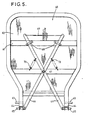
- the main portions 22 of each member 19 are secured in rigid parallel relationship by rigid integral transverse portions 23 disposed adjacent the median pivot means 17 and between projecting end portions 24 and 25 or 26 and 27 of the main portions 22, as shown in Figures 3 and 4.
- One or more of the extreme transverse portions 23 may be hollow and extend to the ends of the rigid member 19 whereby to close the gap between the end portions 24 and 24; 25, 25; 26, 26; and/or 27 and 27, whereby to further integrally unite said end portions.
- the median pivot means 17 each comprise a rigid metal rod 28 which extends through axially elongate bearing sockets 29 ( Figure 4) so as to extend transversely horizontally across the linkage device 20 or 21.
- the connector means 18 comprises parallel intermediate pivot means 30, each comprising a metal rod 31 or 32 which extends across the linkage devices and through bearing sockets 29.
- the rod 32 connects the upper end portions 26 of the member 19 of the linkage device 21 to the lower end portions 33 of the member 16 of the upper linkage device 20; and the rod 31 similarly connects the lower end portions 25 to the upper end portions 34 of the members 16 of the lower linkage device 21.
- the platform and base have releasably secured thereto respective pairs of mutually opposed upper guides 35 or lower guides 36, which guides are of channel form and are arranged in parallel and are offset outwardly from the linkage devices 20, 21.
- the upper end portions 24 support a further metal rod 37 in bearing sockets 29 which rod provides outwardly projecting end portions (not shown) each of which is secured fixedly to an end part of an upper guide 35 and is bedded in a plastics block 38 fixed in the guide 35.
- the lower end portions 27 similarly support a further metal rod 39, which rod provides outwardly projecting end portions (not shown) bedded in plastics-block sliders 40 which are a tight sliding fit n the lower guide 36.
- the end portions 24 and 27 are extended outwards adjacent to the guides 35, 36 to further support the rods 37, 39.
- the rods 28, 31, 32, 37 and 39 provide bracing for the end portions and are a close or push fit in the bearing sockets 29.
- the upper end portions 41 of the members 16 of the upper linkage device 20 may support a rod similar to the rod 39 having end portions bedded in plastics block sliders 42 in the upper guides 35, and the lower end portions 43 of the members 16 of the lower linkage device 21 may support a rod similar to the rod 37 having end portions bedded in plastics blocks 44 fixed in the lower guides 36.
- the linkage devices 20, 21 are provided with tie means 45 which comprises a rigid upper bar 46 extending horizontally between and secured to the upper end portions 41 and a similar lower bar 47 secured to the lower end portion 43, which tie means 45 is proximal to the end portions 25 and 26 when the apparatus is in the lowered position shown in - Figure 1.
- the tie means 45 provides rigid spacing and bracing for the end portions 41 and 43 so that a weight saving can be made by mounting respective individual short rods 48, 49 in said end portions 41 and 43 to engage in the sliders 42 and blocks 44.
- the outwardly projecting end portions may be slidable in low-friction plastics channel section inserts in the guides, e.g. as indicated at 142 in Figure 3.
- the rods 37 and 49 respectively serve as upper pivot means and lower pivot means which provide an upper horizontal common fixed axis and a lower horizontal common fixed axis vertically below and parallel with the upper common fixed axis so that the end portions 24 and 43 are restricted solely to pivoted movement relative to the platform 11 and base 10; and the rods 39 and 48 respectively serve as lower main pivot means and upper main pivot means which provide lower and upper horizontal common main axes 50, 51 ( Figure 3) for pivotal movement of the end portions 27 and 41 relative to the sliders 40, 42, which axes 50 and 51 are solely horizontally movable in unison relative to the guides 36, 35 so that the upper main axis 51 remains vertically above and parallel with the lower main axis 50.
- the relatively large axial length to diameter ratio (e.g. at least 2:1) of the. bearing sockets in combination with the close or tight fit of the rods in the bearing sockets, blocks and sliders prevent any significant unwanted movements of said axes from their precisely parallel relationships; and serve to minimise wear. Furthermore, only the linearly sliding surfaces of the sliders are subjected to any slow but significant wear during repeated operation, and these sliders can be replaced cheaply and easily after simple removal of the guides which thus serve as releasable connecting means connecting the stabilising means 14 to the base and platform.
- the sliders may be replaced by rollers or like rotatable elements.
- the flexible wall 15 is of segmental construction and, as indicated in Figure 3, comprises strips 52 of impervious flexible but substantially inelastic material bonded together at outer junctions 53 and bonded together and to stiffeners 54 at inner junctions 55.
- the stiffeners 54 are of flattened cross-section, have rounded or tapered edges, and are substantially rectangular in plan.
- the lowermost and uppermost strips 52 are respectively clamped to the base 10, e.g. by a clamping ring 56 and fasteners 57, and similarly to the platform 11, so as to effect a seal therewith to render the thrust means 12 airtight except for the means 13, whereby to allow the platform to be raised or lowered by inflation or deflation of the thrust means.
- the large area bellows allows a large load to be lifted by a direct thrust on the platform so that the stabilising means is not subjected to any lifting loads.
- a load of about 100 kg can be lifted on a platform of about 0.15 m 2 in area through a distance of 40 cm by a pneumatic supply pressure of only about 0.35 kg/ cm 2 .
- the lifting apparatus may be arranged to support and lift a person, and in this embodiment comprises a backrest assembly 60, which assembly comprises a frame 61, a moulded plastics facing 62, oppositely directed lugs 63 on lower portions 64 of the frame, bolts 65 slidably mounted on the lower portions 64, crossed levers 66 connected to the bolts and pivotally mounted by a central pivot 67 and guides 68 on the frame, and a cross-rope 69 connecting the upper ends of the levers 66, which rope 69, when pulled upwards, causes the bolts 65 to be retracted inwards, against a bias provided by springs 70.
- a backrest assembly 60 which assembly comprises a frame 61, a moulded plastics facing 62, oppositely directed lugs 63 on lower portions 64 of the frame, bolts 65 slidably mounted on the lower portions 64, crossed levers 66 connected to the bolts and pivotally mounted by a central pivot 67 and guides 68 on the frame, and a cross-rope
- the rear of the platform 11 is shaped to provide a pair of mountings 71, each of which provides an upwardly open socket 72 for one of the lugs 63, and a parallel downwardly open socket 73 to accept one of the bolts 65 to secure the backrest assembly for the platform.
- the backrest assembly 60 can be simply lifted off the platform.
- the platform 11 also has, along each side, an elongate and headed protuberance 74 joined to the platform by a neck 75.
- the protuberances 74 serve as mountings for slide-on supports 76 (for armrests or like fittings) having clamping screws 77 to secure the supports 76 in fixed positions on the platform as shown in Figure 6, or as mountings for flank panels 78 shown in Figure 7 and indicated in broken lines in Figure 1.
- the flank panels 78 operate and are used as described in British Patent Specification No. 2110527, and are secured to the mountings 74, 75 by a plastics hinge 79 comprising a first elongate portion 80 shaped to fit onto the mounting, a second portion 81 secured to the panel 78 and a thin flexible portion 82 connecting the portions 80 and 81.
- the hinge is a unitary/co-extrusion of relatively rigid plastics material, which forms the portions 80, 81, and a relatively flexible plastics material which forms the portion 82.
- the base 10 is provided with four swivel mounted suckers 84, and a lift limiting cord 85 to actuate the means 13 to limit inflation of the thrust means.
- the cord 85 may be adjustably secured to the platform, backrest or armrest.
- the connecting means may comprise an intermediate extensible linkage device and two additional rods similar to the rods 32,31.
- the or any of the rods which extend across the linkage devices may be replaced by pairs of co-axially aligned pairs of short rods, e.g. similar to the rods 48 and 49, to connect together the rigid members orto connectthe rigid members to the blocks or sliders, and permit arcuate movement about said axes, whereby to provide the or any one of the several pivot means.
- the rigid members, guides, mountings and pivots may be of any suitable construction and configuration.
- the rigid members may be cast so as to have rounded edges.
- the stabilising means may incorporate stops, dampers, shock absorbers or bias means, to limit, smooth or bias the movement of the rollers or sliders relative to the guides.
- the flexible wall may be of any suitable form and of any suitable construction; and may be secured to the platform and base in any suitable manner.
- the corners of the wall may be rounded to facilitate sealing.
- Connectors may be included to enable several units of the apparatus to be arranged in a stack or row and connected to operate sequentially or in unison.
- the connectors may incorporate self sealing fluid couplings.
- the apparatus is particularly suitable for operation by means of a low pressure compressed air supply; and preferably includes manually operable valve means, to control admission and. release of air into and from the thrust means, and a pressure relief valve to limit the maximum working air pressure within the thrust means.
- the apparatus may include manually releasable safety means to hold the platform at a selected or predetermined height.
- the apparatus is capable of being used in a wide variety of applications, may carry a variety of fittings, and may be mounted on a variety of supports.
- the base and platform may be shaped to suit the supports and fittings, and may include a removable or openable inspection or maintenance hatch or panel to provide access to the linkages and other components within the thrust means.
- the apparatus may be operated in any required orientation, e.g. may be inclined to the vertical or may be horizontal, the terms “vertical”, “horizontal” and “front” being used herein in relation to the apparatus when orientated as shown in the drawings.
Landscapes
- Health & Medical Sciences (AREA)
- Life Sciences & Earth Sciences (AREA)
- Nursing (AREA)
- Animal Behavior & Ethology (AREA)
- General Health & Medical Sciences (AREA)
- Public Health (AREA)
- Veterinary Medicine (AREA)
- Geology (AREA)
- Engineering & Computer Science (AREA)
- Mechanical Engineering (AREA)
- Structural Engineering (AREA)
- Forging (AREA)
- Lift-Guide Devices, And Elevator Ropes And Cables (AREA)
- Massaging Devices (AREA)
- Invalid Beds And Related Equipment (AREA)
- Vibration Prevention Devices (AREA)
- Auxiliary Methods And Devices For Loading And Unloading (AREA)
- Tables And Desks Characterized By Structural Shape (AREA)
Claims (13)
Priority Applications (1)
| Application Number | Priority Date | Filing Date | Title |
|---|---|---|---|
| AT85307440T ATE39912T1 (de) | 1984-11-06 | 1985-10-16 | Hebevorrichtung. |
Applications Claiming Priority (6)
| Application Number | Priority Date | Filing Date | Title |
|---|---|---|---|
| GB8428009 | 1984-11-06 | ||
| GB848428009A GB8428009D0 (en) | 1984-11-06 | 1984-11-06 | Lifting apparatus |
| GB858502950A GB8502950D0 (en) | 1985-02-06 | 1985-02-06 | Lifting apparatus |
| GB8502950 | 1985-02-06 | ||
| GB08524851A GB2166415B (en) | 1984-11-06 | 1985-10-09 | Lifting apparatus |
| GB8524851 | 1985-10-09 |
Publications (2)
| Publication Number | Publication Date |
|---|---|
| EP0181708A1 EP0181708A1 (de) | 1986-05-21 |
| EP0181708B1 true EP0181708B1 (de) | 1989-01-11 |
Family
ID=27262505
Family Applications (1)
| Application Number | Title | Priority Date | Filing Date |
|---|---|---|---|
| EP85307440A Expired EP0181708B1 (de) | 1984-11-06 | 1985-10-16 | Hebevorrichtung |
Country Status (5)
| Country | Link |
|---|---|
| US (2) | US4688760A (de) |
| EP (1) | EP0181708B1 (de) |
| AT (1) | ATE39912T1 (de) |
| DE (1) | DE3567436D1 (de) |
| GB (1) | GB2166415B (de) |
Cited By (1)
| Publication number | Priority date | Publication date | Assignee | Title |
|---|---|---|---|---|
| RU2760861C2 (ru) * | 2020-05-19 | 2021-12-01 | Борис Лаврович Макеев | Приставка к ванне для людей с ограниченными возможностями |
Families Citing this family (67)
| Publication number | Priority date | Publication date | Assignee | Title |
|---|---|---|---|---|
| NL8502471A (nl) * | 1985-09-10 | 1987-04-01 | Talson Transport Engineering | Vrachtvoertuig, in het bijzonder van het type oplegger, met een aan de voorzijde verhoogde laadvloer. |
| GB2225558B (en) * | 1988-09-29 | 1992-07-29 | Mangar Aids Ltd | Wheelchair apparatus |
| NL8900557A (nl) | 1989-03-07 | 1990-10-01 | Rolflex Oost Nederland | Beweegbare laadbrug. |
| GB2237188B (en) * | 1989-07-22 | 1992-11-18 | Mangar Aids Ltd | Improvements in or relating to invalid seating |
| GB8926066D0 (en) * | 1989-11-17 | 1990-01-10 | Arjo Mecanaids | Apparatus for assisting physically disabled persons into and out of a bath |
| USD334862S (en) | 1991-02-22 | 1993-04-20 | Harris Mark I | Lifting cushion for disabled persons |
| US5299906A (en) * | 1991-05-03 | 1994-04-05 | Stone Robert M | Self-adjusting pneumatic load elevator |
| KR100208845B1 (ko) * | 1991-12-26 | 1999-07-15 | 로버트 제이. 워너 | 팽창가능한 백을 사용한 도크 레벨링 장치 |
| US5996156A (en) * | 1995-01-31 | 1999-12-07 | Kelley Company, Inc. | Dock leveler raised by deflating an inflatable member |
| US5481774A (en) * | 1993-10-04 | 1996-01-09 | Kelley Company, Inc. | Support mechanism for a dockleveler lift bag |
| US5600859A (en) * | 1995-01-31 | 1997-02-11 | Kelley Company, Inc. | Dock leveler in which the ramp is raised and lowered using an inflatable member and method of use |
| US5471693A (en) * | 1993-10-04 | 1995-12-05 | Kelley Company Inc. | Support and attachment mechanism for a dockleveler lift bag |
| US5802650A (en) * | 1993-10-04 | 1998-09-08 | Kelley Company, Inc. | Dock leveler having an inflatable member |
| US5446938A (en) * | 1993-10-04 | 1995-09-05 | Kelley Company Inc. | Bag construction for a dockleveler |
| US6460212B2 (en) | 1993-10-04 | 2002-10-08 | Kelley Company, Inc. | Dock leveler having an inflatable member |
| US6711774B2 (en) | 1993-10-04 | 2004-03-30 | Kelley Company, Inc. | Dock leveler having an inflatable member |
| US5450643A (en) * | 1993-10-04 | 1995-09-19 | Kelley Company Inc. | Edge-of-dock leveler |
| US5529573A (en) * | 1993-11-15 | 1996-06-25 | Danninger Medical Technology, Inc. | Pneumatic fluid actuated continuous passive motion device |
| US5506012A (en) * | 1994-04-01 | 1996-04-09 | Engineered Fabrics Corp. | Multiple chambered lift bag |
| US5669086A (en) * | 1994-07-09 | 1997-09-23 | Mangar International Limited | Inflatable medical lifting devices |
| GB2296429B (en) * | 1994-12-31 | 1998-11-25 | Mangar International Ltd | Lifting apparatus |
| US5522107A (en) * | 1995-01-31 | 1996-06-04 | Kelley Company, Inc. | Retaining arrangement for an inflatable member in a dock leveler |
| US5475888A (en) * | 1995-01-31 | 1995-12-19 | Kelley Company, Inc. | Lip lifting mechanism for a dock leveler |
| US5522108A (en) * | 1995-01-31 | 1996-06-04 | Kelley Company, Inc. | Dock leveler having a ramp movable to a raised position by inflation of an inflatable member, with a filler for occupying volume within the inflatable member |
| US5542806A (en) * | 1995-03-31 | 1996-08-06 | The Champion Company | Fluid actuated lifting and tilting device |
| GB9613079D0 (en) * | 1996-06-21 | 1996-08-28 | Mangar International Ltd | Lifting apparatus |
| GB2324028B (en) * | 1997-04-09 | 2001-01-10 | Mangar Int Ltd | Lifting seat apparatus |
| GB9709843D0 (en) * | 1997-05-15 | 1997-07-09 | Mangar International Ltd | Inflatable cushion |
| US6286813B1 (en) | 1997-12-05 | 2001-09-11 | Albert V. Coccaro | Automotive jack employing a pneumatic lifting system |
| US5934414A (en) * | 1998-01-07 | 1999-08-10 | Staczek; James J. | Lifting apparatus |
| EP0956847A3 (de) * | 1998-04-27 | 2000-04-12 | Dieter Gobbers | Sitzvorrichtung zum Einsetzen in eine Dusch- oder Badewanne |
| DE19818821C2 (de) | 1998-04-27 | 2000-07-27 | Dieter Gobbers | Hubvorrichtung zum Heben eines Rollstuhls |
| FR2790928A1 (fr) * | 1999-03-18 | 2000-09-22 | Moira Dilillo Philibert | Tabouret pliant portatif |
| GB2349917B (en) * | 1999-05-11 | 2003-12-10 | Mangar Int Ltd | Fluid operable ram |
| DE19928829A1 (de) * | 1999-06-24 | 2001-01-04 | Huelsta Werke Huels Kg | Sitzmöbel mit einem höhenverstellbaren Sitz |
| US6286812B1 (en) | 2000-03-27 | 2001-09-11 | Autoquip Corporation | Portable lifting apparatus |
| US6871364B1 (en) * | 2000-04-21 | 2005-03-29 | Thomas Leoutsakos | Foot lift |
| US6457192B2 (en) * | 2000-10-04 | 2002-10-01 | Harrison Choi | Air bed with elevated and self-expanding support structure |
| DE10107622B4 (de) * | 2001-02-17 | 2005-10-20 | Aquatec Gmbh & Co Kg | Badewannenlifter |
| GB0107999D0 (en) * | 2001-03-30 | 2001-05-23 | Mangar Int Ltd | Lifting and lowering apparatus |
| US7062814B2 (en) * | 2002-05-06 | 2006-06-20 | Rite-Hite Holding Corporation | Inflatable column assembly for a dock leveler |
| US20040221404A1 (en) * | 2003-04-28 | 2004-11-11 | Brian Bender | Double-wall inflatable column assembly for a dock leveler |
| CA2549793A1 (en) * | 2003-12-17 | 2005-06-30 | David T. Davis | Pneumatic lift |
| US6971837B1 (en) | 2003-12-31 | 2005-12-06 | Honda Motor Co., Ltd. | Stack handling and handwork table |
| US8191865B2 (en) | 2004-05-17 | 2012-06-05 | Stertil B.V. | Device and system for lifting a motor vehicle |
| US20070000048A1 (en) * | 2004-12-16 | 2007-01-04 | Davis David T | Pneumatic lift and method for transferring an invalid patient |
| US7364623B2 (en) * | 2005-01-27 | 2008-04-29 | Lam Research Corporation | Confinement ring drive |
| US7503089B2 (en) * | 2005-04-05 | 2009-03-17 | Rite-Hite Holding Corporation | Inflatable actuator for a dock leveler deck |
| CN201119618Y (zh) * | 2007-02-15 | 2008-09-24 | 厦门进雄企业有限公司 | 一种折叠支撑架及交叉架 |
| US20080251409A1 (en) * | 2007-04-13 | 2008-10-16 | Frank Hessemer | Container |
| US8469152B2 (en) * | 2007-09-25 | 2013-06-25 | Hunter Engineering Company | Methods and systems for multi-capacity vehicle lift system |
| DE102007057481B4 (de) * | 2007-11-29 | 2010-06-24 | Festo Ag & Co. Kg | Verfahren zum Betreiben einer Warenpräsentationseinrichtung |
| US8813916B2 (en) * | 2008-04-16 | 2014-08-26 | Clear View Enclosures, Inc. | Underground enclosure system for storing components, cables, and the like |
| US8366118B2 (en) * | 2008-06-12 | 2013-02-05 | Clear View Enclosures, Inc. | Retention system for an inflatable seal |
| GB0816408D0 (en) * | 2008-09-09 | 2008-10-15 | Mangar Internat Holdings Ltd | Inflatable lifting devices |
| US8519263B2 (en) * | 2009-05-14 | 2013-08-27 | Clear View Enclosures, Inc. | Below ground component enclosure |
| US8413277B2 (en) * | 2009-10-13 | 2013-04-09 | Woodlark Circle, Inc. | Pneumatic lift with unidirectional valve |
| US8240691B2 (en) | 2009-12-02 | 2012-08-14 | Safe And Secure Products, Inc. | Manual wheelchair lift and methods of using same |
| US20200405561A1 (en) * | 2012-08-12 | 2020-12-31 | Michael Campagna | Medical Imaging Compatible Radiolucent Surgical Device Pneumatic Lift |
| USD739111S1 (en) * | 2013-05-04 | 2015-09-15 | Eustace L. Arrindell | Inflatable automobile jack |
| US8911021B1 (en) | 2013-09-20 | 2014-12-16 | Paul Styke | Apparatus for raising and lowering a human foot |
| US9675508B2 (en) * | 2014-08-25 | 2017-06-13 | Shawn Anthony Hall | Apparatus for lifting a chair |
| CN107048792B (zh) * | 2017-03-31 | 2019-03-08 | 永艺家具股份有限公司 | 升降坐具 |
| GB2580912B (en) * | 2019-01-29 | 2023-02-08 | Roma Medical Ltd | Apparatus |
| US10639220B1 (en) * | 2019-03-15 | 2020-05-05 | Donna Marie Antoinette Smith | Collapsible personal lift |
| NL2027161B1 (nl) * | 2020-12-18 | 2022-07-15 | Jpm Beheer B V | Hefsysteem |
| US11964857B2 (en) * | 2021-09-28 | 2024-04-23 | Best Process Solutions, Inc. | Lift and guard |
Citations (3)
| Publication number | Priority date | Publication date | Assignee | Title |
|---|---|---|---|---|
| EP0074053A2 (de) * | 1981-09-08 | 1983-03-16 | Siemens Aktiengesellschaft | Behandlungsliege |
| EP0074460A1 (de) * | 1981-09-01 | 1983-03-23 | Peter Schmidt | Badewanneneinsatz |
| EP0121348A1 (de) * | 1983-03-08 | 1984-10-10 | Alpha Lifts Limited | Aufzug |
Family Cites Families (12)
| Publication number | Priority date | Publication date | Assignee | Title |
|---|---|---|---|---|
| DE513561C (de) * | 1929-01-17 | 1930-11-29 | Gustav Schlick | Nahtloser Federungskoerper mit ringfoermig in sich geschlossenen Falten, insbesondere fuer Membranpumpen |
| US1846607A (en) * | 1931-07-22 | 1932-02-23 | Eldridge H Nicholas | Folding stool |
| US2070960A (en) * | 1936-01-11 | 1937-02-16 | Rodney F Phillips | Jack |
| US2725578A (en) * | 1952-03-28 | 1955-12-06 | Keller-Erne Lina | Transporting devices for invalids for use in bathtubs and like receptacles |
| US2747692A (en) * | 1952-09-29 | 1956-05-29 | Tracy S Holmes | Foot actuated, ground engaging brake for hand trucks and the like |
| US3412873A (en) * | 1966-06-20 | 1968-11-26 | Meyer Geo J Mfg Co | Centering and lifting means for an automatic case loader |
| US3401607A (en) * | 1966-08-08 | 1968-09-17 | Michael L. Wortman | Reciprocating bellows |
| US3695582A (en) * | 1970-11-02 | 1972-10-03 | Max R Wheeler | Pneumatic jack for motor vehicles |
| DE7533295U (de) * | 1975-10-20 | 1976-02-26 | Vetter, Manfred, 5352 Zuelpich | Hebekissen zum heben, stuetzen und verschieben von lasten |
| FR2405209A1 (fr) * | 1977-10-06 | 1979-05-04 | Dunlop Sa | Appareil de levage |
| US4560145A (en) * | 1979-04-09 | 1985-12-24 | Widmer Stanley W | Air bag jack |
| GB2110527B (en) * | 1981-04-29 | 1984-12-19 | David Edmund Talbot Garman | Apparatus for supporting disabled persons |
-
1985
- 1985-10-09 GB GB08524851A patent/GB2166415B/en not_active Expired
- 1985-10-16 EP EP85307440A patent/EP0181708B1/de not_active Expired
- 1985-10-16 AT AT85307440T patent/ATE39912T1/de not_active IP Right Cessation
- 1985-10-16 DE DE8585307440T patent/DE3567436D1/de not_active Expired
- 1985-11-01 US US06/794,502 patent/US4688760A/en not_active Expired - Lifetime
-
1987
- 1987-05-21 US US07/052,397 patent/US4786032A/en not_active Expired - Fee Related
Patent Citations (3)
| Publication number | Priority date | Publication date | Assignee | Title |
|---|---|---|---|---|
| EP0074460A1 (de) * | 1981-09-01 | 1983-03-23 | Peter Schmidt | Badewanneneinsatz |
| EP0074053A2 (de) * | 1981-09-08 | 1983-03-16 | Siemens Aktiengesellschaft | Behandlungsliege |
| EP0121348A1 (de) * | 1983-03-08 | 1984-10-10 | Alpha Lifts Limited | Aufzug |
Cited By (1)
| Publication number | Priority date | Publication date | Assignee | Title |
|---|---|---|---|---|
| RU2760861C2 (ru) * | 2020-05-19 | 2021-12-01 | Борис Лаврович Макеев | Приставка к ванне для людей с ограниченными возможностями |
Also Published As
| Publication number | Publication date |
|---|---|
| US4786032A (en) | 1988-11-22 |
| EP0181708A1 (de) | 1986-05-21 |
| GB2166415B (en) | 1988-10-12 |
| GB8524851D0 (en) | 1985-11-13 |
| US4688760A (en) | 1987-08-25 |
| GB2166415A (en) | 1986-05-08 |
| ATE39912T1 (de) | 1989-01-15 |
| DE3567436D1 (en) | 1989-02-16 |
Similar Documents
| Publication | Publication Date | Title |
|---|---|---|
| US4688760A (en) | Lifting apparatus | |
| US11154445B2 (en) | Bed systems and methods | |
| US10188567B2 (en) | Hospital chair beds with extendable/retractable foot sections | |
| US3336606A (en) | Bed for persons having physical disability | |
| US9107781B1 (en) | Height adjustable apparatus with opposed legs movably and pivotally connected to rails supporting a deck | |
| US8321976B1 (en) | Height adjustable apparatus with control arm | |
| EP0303317B1 (de) | Verstellbarer Auflagetisch für medizinische Zwecke | |
| US20050046129A1 (en) | Constant center of gravity lift and tilt mechanisms for a wheelchair seat | |
| US20020148044A1 (en) | Patient support | |
| US11071667B2 (en) | Hospital chair beds with extendable/retractable foot sections | |
| WO2016069730A1 (en) | Leg assembly for height adjustable patient support | |
| CN106473451B (zh) | 可控气弹簧升降桌 | |
| CN112972160A (zh) | 一种用于转移车的移位装置及平躺移位床 | |
| EP4076326B1 (de) | Betthubmechanik | |
| CZ306806B6 (cs) | Zdravotnický prostředek s teleskopickým podpěrným sloupem | |
| CN117481455A (zh) | 桌面升降工作台 | |
| EP4076325B1 (de) | Betthebemechanismus | |
| JPS61114999A (ja) | リフト装置 | |
| FR2592301B1 (fr) | Fauteuil roulant pliant elevateur. | |
| CN117090123A (zh) | 一种码头登船平台电控贯通道 | |
| CN118217099A (zh) | 一种具有输送带的手术室平移转运车 | |
| WO2014053856A1 (en) | Patient lifting device | |
| ITFI940126A1 (it) | Supporto estensibile atto a regolare la distanza e/o l'inclinazione di una generica struttura rispetto ad un piano di riferimento e letto os |
Legal Events
| Date | Code | Title | Description |
|---|---|---|---|
| PUAI | Public reference made under article 153(3) epc to a published international application that has entered the european phase |
Free format text: ORIGINAL CODE: 0009012 |
|
| AK | Designated contracting states |
Kind code of ref document: A1 Designated state(s): AT BE CH DE FR GB IT LI LU NL SE |
|
| 17P | Request for examination filed |
Effective date: 19860818 |
|
| 17Q | First examination report despatched |
Effective date: 19871020 |
|
| GRAA | (expected) grant |
Free format text: ORIGINAL CODE: 0009210 |
|
| AK | Designated contracting states |
Kind code of ref document: B1 Designated state(s): AT BE CH DE FR IT LI LU NL SE |
|
| PG25 | Lapsed in a contracting state [announced via postgrant information from national office to epo] |
Ref country code: AT Effective date: 19890111 |
|
| REF | Corresponds to: |
Ref document number: 39912 Country of ref document: AT Date of ref document: 19890115 Kind code of ref document: T |
|
| ITF | It: translation for a ep patent filed | ||
| REF | Corresponds to: |
Ref document number: 3567436 Country of ref document: DE Date of ref document: 19890216 |
|
| ET | Fr: translation filed | ||
| PG25 | Lapsed in a contracting state [announced via postgrant information from national office to epo] |
Ref country code: LU Free format text: LAPSE BECAUSE OF NON-PAYMENT OF DUE FEES Effective date: 19891031 |
|
| PLBE | No opposition filed within time limit |
Free format text: ORIGINAL CODE: 0009261 |
|
| STAA | Information on the status of an ep patent application or granted ep patent |
Free format text: STATUS: NO OPPOSITION FILED WITHIN TIME LIMIT |
|
| 26N | No opposition filed | ||
| ITTA | It: last paid annual fee | ||
| PGFP | Annual fee paid to national office [announced via postgrant information from national office to epo] |
Ref country code: CH Payment date: 19941011 Year of fee payment: 10 |
|
| PGFP | Annual fee paid to national office [announced via postgrant information from national office to epo] |
Ref country code: NL Payment date: 19941031 Year of fee payment: 10 |
|
| PGFP | Annual fee paid to national office [announced via postgrant information from national office to epo] |
Ref country code: BE Payment date: 19941110 Year of fee payment: 10 |
|
| EAL | Se: european patent in force in sweden |
Ref document number: 85307440.9 |
|
| ITPR | It: changes in ownership of a european patent |
Owner name: CAMBIO RAGIONE SOCIALE;MANGAR INTERNATIONAL LIMITE |
|
| REG | Reference to a national code |
Ref country code: CH Ref legal event code: PFA Free format text: MANGAR INTERNATIONAL LIMITED |
|
| NLT1 | Nl: modifications of names registered in virtue of documents presented to the patent office pursuant to art. 16 a, paragraph 1 |
Owner name: MANGAR INTERNATIONAL LIMITED |
|
| PGFP | Annual fee paid to national office [announced via postgrant information from national office to epo] |
Ref country code: SE Payment date: 19951017 Year of fee payment: 11 |
|
| REG | Reference to a national code |
Ref country code: FR Ref legal event code: CD |
|
| PG25 | Lapsed in a contracting state [announced via postgrant information from national office to epo] |
Ref country code: LI Effective date: 19951031 Ref country code: CH Effective date: 19951031 Ref country code: BE Effective date: 19951031 |
|
| BERE | Be: lapsed |
Owner name: MANGAR INTERNATIONAL LTD Effective date: 19951031 |
|
| PG25 | Lapsed in a contracting state [announced via postgrant information from national office to epo] |
Ref country code: NL Effective date: 19960501 |
|
| REG | Reference to a national code |
Ref country code: CH Ref legal event code: PL |
|
| NLV4 | Nl: lapsed or anulled due to non-payment of the annual fee |
Effective date: 19960501 |
|
| PG25 | Lapsed in a contracting state [announced via postgrant information from national office to epo] |
Ref country code: SE Effective date: 19961017 |
|
| EUG | Se: european patent has lapsed |
Ref document number: 85307440.9 |
|
| PGFP | Annual fee paid to national office [announced via postgrant information from national office to epo] |
Ref country code: FR Payment date: 19971029 Year of fee payment: 13 |
|
| PGFP | Annual fee paid to national office [announced via postgrant information from national office to epo] |
Ref country code: DE Payment date: 19980411 Year of fee payment: 13 |
|
| PG25 | Lapsed in a contracting state [announced via postgrant information from national office to epo] |
Ref country code: FR Free format text: LAPSE BECAUSE OF NON-PAYMENT OF DUE FEES Effective date: 19990630 |
|
| REG | Reference to a national code |
Ref country code: FR Ref legal event code: ST |
|
| PG25 | Lapsed in a contracting state [announced via postgrant information from national office to epo] |
Ref country code: DE Free format text: LAPSE BECAUSE OF NON-PAYMENT OF DUE FEES Effective date: 19990803 |