EP0181758A1 - Gerät zum Messen der Ausrichtung von Rädern - Google Patents
Gerät zum Messen der Ausrichtung von Rädern Download PDFInfo
- Publication number
- EP0181758A1 EP0181758A1 EP85308007A EP85308007A EP0181758A1 EP 0181758 A1 EP0181758 A1 EP 0181758A1 EP 85308007 A EP85308007 A EP 85308007A EP 85308007 A EP85308007 A EP 85308007A EP 0181758 A1 EP0181758 A1 EP 0181758A1
- Authority
- EP
- European Patent Office
- Prior art keywords
- wheel
- ground
- attitude
- contact
- formations
- Prior art date
- Legal status (The legal status is an assumption and is not a legal conclusion. Google has not performed a legal analysis and makes no representation as to the accuracy of the status listed.)
- Withdrawn
Links
Images
Classifications
-
- G—PHYSICS
- G01—MEASURING; TESTING
- G01B—MEASURING LENGTH, THICKNESS OR SIMILAR LINEAR DIMENSIONS; MEASURING ANGLES; MEASURING AREAS; MEASURING IRREGULARITIES OF SURFACES OR CONTOURS
- G01B5/00—Measuring arrangements characterised by the use of mechanical techniques
- G01B5/24—Measuring arrangements characterised by the use of mechanical techniques for measuring angles or tapers; for testing the alignment of axes
- G01B5/255—Measuring arrangements characterised by the use of mechanical techniques for measuring angles or tapers; for testing the alignment of axes for testing wheel alignment
Definitions
- This invention relates to apparatus for testing the alignment of a pair of wheels of a motor vehicle.
- the wheels whose alignment is required to be checked are the front wheels of the vehicle, and the alignment parameter of interest is toe-in or toe-out thereof, but other aspects of wheel and suspension geometry can of course be measured.
- Wheel alignment checking apparatus comprising, for each wheel, a member adapted to be connected to the wheel so as to take up the attitude of the wheel.
- the members are connected to the wheels by clip or clamp devices, engagable with the wheel rim or other part of the wheel or hub.
- the members have means for communicating their attitudes to one another to provide a measure of the alignment of the wheels.
- Commonly such communicating means is an optical system comprising a projector for a light beam, a mirror, and a scale which can be calibrated to provide a direct read out of the wheel alignment parameter required.
- apparatus for testing the alignment of a pair of wheels of a motor vehicle comprising, for each wheel, a member having formations adapted to contact a part of the wheel so that said member takes up the attitude of the wheel, and means for communicating the attitude of said member to the member having the attitude of the other wheel of the pair, characterised in that said member is carried by a ground-engaging supporting means, and there is provided an element adapted to be pressed into engagement with said wheel and the ground, and having a portion which then abuts said member so that said member is held with said formations thereof in contact with said part of the wheel.
- the support of the member which takes up the attitude of the wheel by the ground-engaging supporting structure eliminates the necessity for clamps or like means for securing the member to the wheel itself.
- the formations which contact the wheel part, e.g. the rim, so that the member takes up the wheel's attitude need merely abut a convenient surface of the wheel part.
- the element which is adapted to engage the wheel and ground does not have to support the weight of the member taking up the attitude of the wheel, but merely ensure that its formations are held in contact with the wheel.
- Said element may comprise two limbs which extend from the portion thereof which abuts said member, such limbs having portions engagable between the tyre and ground in front of and behind the area of contact of the tyre with the ground.
- said element is made by bending a single piece of elongated material, e.g. a metal bar or tube. The effectiveness of the element is increased if it is resilient.
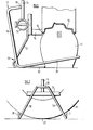
- FIG. 1 there is shown diagrammatically the rim 10 of a vehicle wheel, carrying a tyre 11.
- Apparatus for checking the alignment of the wheel comprises a ground engaging support structure indicated generally at 12. This carries a horizontally extending tubular member 13, with an upwardly extending bar 14 connected thereto.
- the tubular member 13 carries two spaced probes 15 whose position is adjustable so that the probes can contact the edge 16 of the wheel rim at two circumferentially spaced positions.
- Bar 14 carries a further probe, not shown, adjustable to be able to contact the edge of the wheel rim at an upper part thereof.
- the tubular member 13 is thus caused to take up the attitude of the wheel.
- a corresponding member at the wheel on the other side of the vehicle takes up the attitude of that wheel.
- the two members are provided, as is known for wheel alignment checking equipment, with an optical system comprising a projector, mirror and a scale for providing a reading of wheel alignment.
- an optical system comprising a projector, mirror and a scale for providing a reading of wheel alignment.
- other types of means for communicating the attitude of the members may be utilised.
- an element 17 is provided for holding the member 13 such that its probes as 15 are in contact with the edge 16 of the wheel rim.
- This is conveniently a one piece component formed by bending metal bar or thin tube to the shape indicated, which is also shown diagrammatically in Figure 2 from which detail such as the support structure 12 for the tubular member 13 has been omitted.
- the element 15 may be a fabricated structure.
- the element 17 comprises a portion 18 which abuts the bar 14, from opposite ends of which divergent limbs 19 extend.
- the free ends of limbs 19 are bent at right angles to the divergent parts of the limbs, as shown at 20.
- the spacing of parts 20 of the limbs is such that they are able to be pushed, in the direction of arrow 21, between the tyre 11 and the ground at positions in front of and behind the patch of contact 22 between the tyre and ground.
- the effect is one of wedging of the element 17 to exert a force to hold the probes of member 13 in contact with the wheel rim.
- the resilience of element 17 assist in this action.
- element 17 renders the wheel alignment checking apparatus suitable for use with a large range of sizes of wheel without modification, or requiring the use of additional parts.
Landscapes
- Physics & Mathematics (AREA)
- General Physics & Mathematics (AREA)
- A Measuring Device Byusing Mechanical Method (AREA)
- Length Measuring Devices By Optical Means (AREA)
Applications Claiming Priority (2)
| Application Number | Priority Date | Filing Date | Title |
|---|---|---|---|
| GB08428169A GB2166878A (en) | 1984-11-07 | 1984-11-07 | Wheel alignment checking apparatus |
| GB8428169 | 1984-11-07 |
Publications (1)
| Publication Number | Publication Date |
|---|---|
| EP0181758A1 true EP0181758A1 (de) | 1986-05-21 |
Family
ID=10569400
Family Applications (1)
| Application Number | Title | Priority Date | Filing Date |
|---|---|---|---|
| EP85308007A Withdrawn EP0181758A1 (de) | 1984-11-07 | 1985-11-04 | Gerät zum Messen der Ausrichtung von Rädern |
Country Status (2)
| Country | Link |
|---|---|
| EP (1) | EP0181758A1 (de) |
| GB (1) | GB2166878A (de) |
Citations (5)
| Publication number | Priority date | Publication date | Assignee | Title |
|---|---|---|---|---|
| US2781587A (en) * | 1954-12-09 | 1957-02-19 | Haucke Oswin | Wheel aligner |
| US3091862A (en) * | 1959-05-27 | 1963-06-04 | Bear Mfg Co | Aligning device for assisting in centering an automobile steering wheel |
| DE1548224B2 (de) * | 1966-02-04 | 1973-10-31 | Heinrich 7100 Heilbronn Goldbrunner | Vorrichtung zum Befestigen eines Meßspiegeis für ein Achswinkelmeßgerat |
| FR2326680A1 (fr) * | 1975-10-01 | 1977-04-29 | Moniot Philippe | Support pour reglette destinee a permettre l'alignement des roues avant et arriere d'un vehicule |
| DE2708597A1 (de) * | 1976-03-01 | 1977-09-08 | Applied Power Inc | Vorrichtungen, verfahren und anordnungen zum messen und/oder einstellen geometrischer beziehungen an den raedern von fahrzeugen |
Family Cites Families (1)
| Publication number | Priority date | Publication date | Assignee | Title |
|---|---|---|---|---|
| US3135052A (en) * | 1962-12-18 | 1964-06-02 | Bear Mfg Co | Wheel alinement apparatus |
-
1984
- 1984-11-07 GB GB08428169A patent/GB2166878A/en not_active Withdrawn
-
1985
- 1985-11-04 EP EP85308007A patent/EP0181758A1/de not_active Withdrawn
Patent Citations (5)
| Publication number | Priority date | Publication date | Assignee | Title |
|---|---|---|---|---|
| US2781587A (en) * | 1954-12-09 | 1957-02-19 | Haucke Oswin | Wheel aligner |
| US3091862A (en) * | 1959-05-27 | 1963-06-04 | Bear Mfg Co | Aligning device for assisting in centering an automobile steering wheel |
| DE1548224B2 (de) * | 1966-02-04 | 1973-10-31 | Heinrich 7100 Heilbronn Goldbrunner | Vorrichtung zum Befestigen eines Meßspiegeis für ein Achswinkelmeßgerat |
| FR2326680A1 (fr) * | 1975-10-01 | 1977-04-29 | Moniot Philippe | Support pour reglette destinee a permettre l'alignement des roues avant et arriere d'un vehicule |
| DE2708597A1 (de) * | 1976-03-01 | 1977-09-08 | Applied Power Inc | Vorrichtungen, verfahren und anordnungen zum messen und/oder einstellen geometrischer beziehungen an den raedern von fahrzeugen |
Also Published As
| Publication number | Publication date |
|---|---|
| GB8428169D0 (en) | 1984-12-12 |
| GB2166878A (en) | 1986-05-14 |
Similar Documents
| Publication | Publication Date | Title |
|---|---|---|
| CA1142349A (en) | Vehicle frame and body alignment apparatus | |
| US4303338A (en) | Wheel alignment method and apparatus | |
| US4939848A (en) | Vehicle frame alignment gauge | |
| TR200002471T2 (tr) | Bir taşıt tekerleğinin jantına bir aks ölçme aygıtının takılmasına yarayan cihaz | |
| US4408399A (en) | Wheel alignment gauge | |
| US4321754A (en) | Vehicle body-and-frame alignment apparatus | |
| US4407073A (en) | Measuring apparatus for checking a spring strut appertaining to the front wheel suspension of a vehicle | |
| KR850000331A (ko) | 차량 정렬 시스템 | |
| EP0155279A1 (de) | Messextensometer für axial-diametral-durchschnittsspannungsmesswerte | |
| CA2134722C (en) | Methods and apparatus for facilitating a measurement taken from a vehicle wheel axis | |
| US5842281A (en) | Wheelless alignment apparatus and method of using same | |
| US4803785A (en) | Wheel alignment apparatus | |
| US5625953A (en) | Clamping device for vehicle wheel alignment equipment | |
| US5033198A (en) | Four-wheel alignment system | |
| EP0181758A1 (de) | Gerät zum Messen der Ausrichtung von Rädern | |
| US4967480A (en) | Four-wheel alignment and measuring tool | |
| USRE33302E (en) | Macpherson strut alignment gauge and straightening apparatus | |
| US4640015A (en) | Macpherson strut alignment gauge and straightening apparatus | |
| US4167816A (en) | Radius turntable gauge for front end alignment of motor vehicles | |
| USRE32926E (en) | Vehicle body-and-frame alignment apparatus | |
| US5111586A (en) | Vehicle wheel alignment tools | |
| GB2100681A (en) | Measuring apparatus for checking the spring strut of a vehicle front wheel suspension | |
| JPH05802Y2 (de) | ||
| ATE198230T1 (de) | Prüfstand für radaufhängungen von zweiradfahrzeugen | |
| EP0006350B1 (de) | Hilfsgerät zur Ausrichtung von Kraftfahrzeugrädern |
Legal Events
| Date | Code | Title | Description |
|---|---|---|---|
| PUAI | Public reference made under article 153(3) epc to a published international application that has entered the european phase |
Free format text: ORIGINAL CODE: 0009012 |
|
| AK | Designated contracting states |
Kind code of ref document: A1 Designated state(s): AT BE DE FR GB IT LU NL SE |
|
| STAA | Information on the status of an ep patent application or granted ep patent |
Free format text: STATUS: THE APPLICATION IS DEEMED TO BE WITHDRAWN |
|
| 18D | Application deemed to be withdrawn |
Effective date: 19870122 |
|
| RIN1 | Information on inventor provided before grant (corrected) |
Inventor name: SLEATH, BRIAN Inventor name: CAVE, LAWRENCE JOHN |