EP0181813B1 - Flüssigmetallgekühlter schneller Neutronenreaktor mit thermischer Schutzvorrichtung der inneren Struktur - Google Patents
Flüssigmetallgekühlter schneller Neutronenreaktor mit thermischer Schutzvorrichtung der inneren Struktur Download PDFInfo
- Publication number
- EP0181813B1 EP0181813B1 EP85402114A EP85402114A EP0181813B1 EP 0181813 B1 EP0181813 B1 EP 0181813B1 EP 85402114 A EP85402114 A EP 85402114A EP 85402114 A EP85402114 A EP 85402114A EP 0181813 B1 EP0181813 B1 EP 0181813B1
- Authority
- EP
- European Patent Office
- Prior art keywords
- plates
- liquid metal
- internal structures
- structures
- internal
- Prior art date
- Legal status (The legal status is an assumption and is not a legal conclusion. Google has not performed a legal analysis and makes no representation as to the accuracy of the status listed.)
- Expired
Links
Images

Classifications
-
- G—PHYSICS
- G21—NUCLEAR PHYSICS; NUCLEAR ENGINEERING
- G21C—NUCLEAR REACTORS
- G21C11/00—Shielding structurally associated with the reactor
- G21C11/08—Thermal shields; Thermal linings, i.e. for dissipating heat from gamma radiation which would otherwise heat an outer biological shield ; Thermal insulation
- G21C11/083—Thermal shields; Thermal linings, i.e. for dissipating heat from gamma radiation which would otherwise heat an outer biological shield ; Thermal insulation consisting of one or more metallic layers
-
- Y—GENERAL TAGGING OF NEW TECHNOLOGICAL DEVELOPMENTS; GENERAL TAGGING OF CROSS-SECTIONAL TECHNOLOGIES SPANNING OVER SEVERAL SECTIONS OF THE IPC; TECHNICAL SUBJECTS COVERED BY FORMER USPC CROSS-REFERENCE ART COLLECTIONS [XRACs] AND DIGESTS
- Y02—TECHNOLOGIES OR APPLICATIONS FOR MITIGATION OR ADAPTATION AGAINST CLIMATE CHANGE
- Y02E—REDUCTION OF GREENHOUSE GAS [GHG] EMISSIONS, RELATED TO ENERGY GENERATION, TRANSMISSION OR DISTRIBUTION
- Y02E30/00—Energy generation of nuclear origin
- Y02E30/30—Nuclear fission reactors
Definitions
- the present invention relates to a reactor. fast neutron nuclear power cooled by a liquid metal and comprising in a known manner a main tank filled with liquid metal and containing the reactor core, at least one heat exchanger, at least one pump for circulating the liquid metal between the core and the exchanger, and structures internal to the tank for separating inside thereof a relatively hot part of the liquid metal leaving the core from a relatively cold part of the liquid metal leaving the exchanger.
- the internal structures In nuclear reactors of this type, the internal structures generally consist of an internal vessel which can take different forms (cylindrical, with step, etc ...) and passage chimneys for components such as pumps and exchangers, when these are inside the reactor vessel.
- These internal structures are generally made of stainless steel, boiled and mechanically welded. Their function is to separate the relatively hot liquid metal leaving the reactor core from the relatively cold liquid metal leaving the exchangers.
- the liquid metal consists of sodium as is generally the case, the corresponding temperatures are approximately 550 ° C and 400 ° C, respectively.
- the structures reactor internals are subject to normal mechanical problems during normal operation and during transient periods (changes in reactor speed).
- the internal structures of the reactor are subject to phenomena of instability due to internal and external pressures, in particular in the event of earthquakes. These structures are also subjected to fatigue-creep phenomena due to the temperature difference in their thickness, causing the hot face to be compressed.
- a fast neutron nuclear reactor of the type defined above in which the internal structures are covered, on the relatively hot liquid metal side, by a thermal protection device comprising modular plates arranged side by side with a play between them and approximating the shape of the internal structures.
- a thermal protection device comprising modular plates arranged side by side with a play between them and approximating the shape of the internal structures.
- Such a device appreciably improves the behavior of the material (austenitic stainless steel for example) constituting these structures by reducing the average temperature of these structures and the temperature difference in the thickness of these, thus avoiding the phenomenon of fatigue-creep.
- the plates have a complex structure.
- the modular plates are made of a homogeneous metallic material, and have a radius of curvature slightly different from that of the internal structures to be protected, so as to trap static liquid metal between each of the modular plates and these internal structures.
- each plate is fixed to the internal structures by a fixing means placed near the geometric center of said plate.
- the fixing of the plates on the internal structures being preferably carried out by means of a stud welded by sparking on the hot adjacent face of the structures to be protected, security can be provided in the event of rupture of one of the studs.
- This security can be obtained by fixing, in particular by welding, a plate on one of the corners of each plate, so that this plate partially covers the adjacent plates.
- the hot faces of the internal structures having a convex curvature are covered by modular plates having a radius of curvature slightly less than that of these convex faces.
- the hot faces of the internal structures having a concave curvature are covered by modular plates having a radius of curvature slightly greater than that of these concave faces.
- the plates are only in contact with the internal structures at certain points of their peripheral edges. This makes it possible to prevent the corners of the plates yawning and these plates being subjected to vibrations of hydraulic origin.
- each chimney comprising a wave facing the relatively cold part of the liquid metal, and by which said chimney is welded to the step
- the modular plates fixed on the chimney penetrate into the cavity formed by this wave on the side of the relatively hot part of the liquid metal and the modular plates fixed on the step close this cavity .
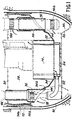
- the fast neutron nuclear reactor partially represented in FIG. 1 comprises in a known manner a cylindrical tank, of vertical axis, called main tank 10 which is received inside a tank well 12 formed in a concrete building ensuring biological protection of the environment.
- the tank 10 can either be suspended from the upper part of the tank well 12, or placed on the bottom of the latter.
- a concrete slab (not shown) simultaneously closes the tank well 12 and the tank 10 in order to complete the biological protection.
- the reactor is of the integrated type, that is to say that the main vessel 10 contains, in addition to the core 14 of the reactor, all the components of the primary circuit of the reactor among which the main ones are the heat exchangers 16 and the primary pumps 18. Although only one of each of these components is shown in FIG. 1, it is known that their number can be variable depending on the power of the reactor.
- the main tank 10 is filled with a liquid metal 20 generally consisting of sodium.
- the circulation of the liquid metal 20 between the core 14 and the exchangers 16 is ensured by the pumps 18 as indicated by the arrows in FIG. 1.
- the relatively hot liquid metal leaving the core 14 at the upper end of it penetrates by inlet orifices 16a in each of the exchangers 16.
- a secondary fluid generally constituted by sodium
- the primary liquid metal leaves the exchangers 16 by outlet orifices 16b. It is then taken up by the suction orifices 18a of the pumps 18, which discharge this relatively cold liquid metal, by pipes 22, into the bed base 24 for supplying and supporting the heart 14, placed immediately below it. this.
- the supply base 24 itself rests on the bottom of the tank 10 by means of a support structure 26 called decking.
- these internal structures 32 consist of a tank internal 34 and chimneys 36 welded to the tank 34.
- the chimneys 36 allow the components to pass through the internal tank while preserving the separation between the relatively hot liquid metal contained in the hot collector 28, generally located above the core 14 and the relatively cold liquid metal contained in the cold collector 30 and generally situated at the periphery of the heart 14.
- the internal tank 34 can take different forms.
- this internal tank 34 mainly comprises a part 34a in the form of a step, through which the pumps 18 and the exchangers 16 pass, and an external ring 34b, substantially cylindrical, the upper edge of which s raises to a level higher than the maximum level of sodium 20 contained in the hot collector 28 during the operation of the pumps 18.
- the chimneys 36 are connected to the part 34a of the tank 34.
- the hot faces of the internal structures 32 are covered by a thermal protection device, the structure of which will now be described in detail with reference to FIGS. 2 and 3.
- the thermal protection device preferably covers all the hot faces of the step 34a, the outer shell 34b and the chimneys 36, it can also be limited to only the parts of the structures 32 most thermally charged, or be adjusted in thickness depending on the thermal stresses prevailing at successive crowns.
- the plates of the same crown have the same thickness, while the plates of different crowns have different thicknesses.
- These plates 38 which act as thermal baffles, are made of a homogeneous material not metallic, and preferably stainless steel.
- the plates 38 have a substantially square or trapezoidal module, the surface of which (for example around 0.25 m2), allows them to be manipulated manually.
- the shape of the plates 38 is designed so as to avoid acute angles, in particular around the chimneys 36 for the passage of the components and to best adapt to the geometry of the internal structures.
- the manufacture of these plates can advantageously be carried out from templates.
- a standard module of plates for each category of ferrules.
- their cutting can be linear, taking into account the large radii of curvature of the latter in front of the relatively small dimensions of the plates.
- the clearance which is provided between the adjacent edges of the plates 38 it must allow the differential expansions between the plates and the internal load-bearing structures 32, while being sufficiently limited so that no current of hot liquid metal can s '' Establish between the structures to be protected and the plates 38. Since the differential expansions between the plates and the supporting structures are small taking into account the dimensions of the plates, it is possible in practice to provide a clearance between plates of the order of 3 to 4 mm incorporating manufacturing tolerances.
- each of the plates 38 is fixed to the adjacent part of the internal structure 32 to be protected by a fixing means placed near the geometric center (or of gravity) of this plate.
- this fixing means preferably consists of a stud 40, welded by sparking on the hot face of the structures 32 to be protected so as to limit its axial thermal gradient.
- the diameter of the stud 40 is dimensioned so as to ensure its mechanical strength. This support mode allows each plate to expand freely from the stud 40 implanted in the center of it.
- this attachment of the plates 38 to the structures 32 can be doubled with an emergency support structure making it possible to hold one of the plates 38 in place in the event of a break in its fixing stud 40.
- This emergency support device comprises plates 42 which are fixed, preferably by welding, on one of the corners of each of the plates 38, so as to partially cover the adjacent plates.
- each of the plates 42 is substantially ten times smaller than that of the protective plates 38 .
- the implantation of the modular plates 38 is made according to rings or crowns, in cylindrical coordinates for the protection of the cylindrical ferrules (external ferrules 34b and chimneys 36 of the components) and in polar coordinates for step 34a. Given the geometry of these structures, some of the plates 38 which cover the step 34a must be curved and some of the plates 38 which cover the ferrules 34b and 36 must be bent.
- the radius of curvature of the plates 38 is slightly different from the radius of curvature of the parts of internal structures on which these plates are fixed, so as to trap between each plate and the part of corresponding internal structure , static liquid metal.
- the presence of static liquid metal between the plates 38 and the support structure 32 makes it possible to define two solid-liquid static interfaces between these two parts. Given the properties of such interfaces from the point of view of thermal conductivity, a significant temperature drop is thus caused at each interface, between the plates 38 which are in contact with the liquid metal contained in the hot collector and the support structure 32.
- FIG. 3 represents in horizontal section part of the shell 34b, the hot internal face of which has a concave curvature.
- the plates 38 then have a radius of curvature greater than that of the internal face of the ferrule, their convex face being turned towards the latter, so as to trap static liquid metal 46 between each plate and the ferrule 34b.
- Only the peripheral edges 38a of the plates 38 are then in elastic abutment on the ferrule 34b, under the effect of the compression resulting from the fixing of the plate to the support structure by the stud 40. This prevents the plates 38 from yawn and they can be stressed by vibrations of hydraulic origin.
- the edges of the edges 38a in contact with the support structure 32 are rounded to avoid the effects of wedges during thermal cycling.
- the curvature of the plates 38 is adapted as a function of the curvature of the part of the structure 32 which supports these plates.
- the ferrule 34b being considered in vertical section, it has rectilinear generators or an infinite curvature.
- the plates 38 then have a very large radius of curvature, the concave face being turned towards the ferrule 34b.
- the plates 38 which are carried by parts of the structure 32 having on their hot face a convex shape as is notably the case for the ferrules 36 considered in horizontal section, have a radius of curvature slightly less than that of these convex parts, their concave faces being turned towards the ferrules 36.
- the thickness of the thermal protection plates 38 is determined as a function of the initial thermal loading, of. so that the stresses and mechanical strength of the entire structure are admissible regardless of the operating conditions.
- This thickness of the plates which can be calculated for each part of the internal structure 32 to be protected, can be for example, depending on the level of thermal stresses, of 5, 10 or 15 mm for a thickness of the internal structure of 30 mm.
- the maximum thickness of the plates does not exceed half the thickness of the structure to be protected.
- the clearance between the adjacent edges of the plates can be approximately 2 mm.
- connection of the passage chimneys 36 on the ferrule 34a is carried out by means of a wave 44 facing the cold collector 30, so as to reduce the average temperature of this region and to relieve the mechanical stresses which are generally high at this level.
- the cavity formed by the wave 44 and turned towards the side of the hot manifold 28 is closed by the plates 38 which provide the thermal protection of the step 34a, so that the liquid metal which is in this cavity is maintained in a quasi-static state.
- the plates 38 ensuring the thermal protection of the chimneys 36 extend to the lower part of this cavity.
- a small width tablet (three to four times the thickness of the shell) can be welded to the upper edge of the external shell 34b of the internal tank, in order to '' improve its rigidity.
- the thermal protection device for the internal structures which has just been described makes it possible, for a minimum bulk and for the same thickness of these internal structures, to reduce their average temperature, the thermal gradient in their thickness, as well as the axial thermal gradient for the ferrules and radial for the step during the transient periods of operation of the reactor, in particular for the ferrules in the zone of variation of the free level of the liquid metal.
- the new design of the connection between the step 34a and the chimneys 36 makes it possible to reduce the mechanical stresses in the isthmus of the step between the component chimneys and in the connections of these chimneys with the step. All these conditions significantly improve the mechanical strength of the internal structures, in particular with regard to the problems of stability and fatigue-creep.
- the invention applies regardless of the shape of the internal structures.
- the thermal protection according to the invention can be used both in the case of an internal stepped tank as we have just described, and in the case of a cylindrical internal tank or any other form.
- the invention is not limited to an integrated type reactor and also applies to a "loop" type reactor, in which the exchangers and, optionally, the pumps, are placed outside of the main tank.
Landscapes
- Engineering & Computer Science (AREA)
- Physics & Mathematics (AREA)
- Health & Medical Sciences (AREA)
- Life Sciences & Earth Sciences (AREA)
- Biomedical Technology (AREA)
- General Health & Medical Sciences (AREA)
- Molecular Biology (AREA)
- Plasma & Fusion (AREA)
- General Engineering & Computer Science (AREA)
- High Energy & Nuclear Physics (AREA)
- Heat-Exchange Devices With Radiators And Conduit Assemblies (AREA)
Claims (7)
Applications Claiming Priority (2)
| Application Number | Priority Date | Filing Date | Title |
|---|---|---|---|
| FR8416995A FR2572838B1 (fr) | 1984-11-08 | 1984-11-08 | Reacteur nucleaire a neutrons rapides refroidi par un metal liquide et dont les structures internes sont equipees d'un dispositif de protection thermique |
| FR8416995 | 1984-11-08 |
Publications (2)
| Publication Number | Publication Date |
|---|---|
| EP0181813A1 EP0181813A1 (de) | 1986-05-21 |
| EP0181813B1 true EP0181813B1 (de) | 1989-07-19 |
Family
ID=9309376
Family Applications (1)
| Application Number | Title | Priority Date | Filing Date |
|---|---|---|---|
| EP85402114A Expired EP0181813B1 (de) | 1984-11-08 | 1985-11-04 | Flüssigmetallgekühlter schneller Neutronenreaktor mit thermischer Schutzvorrichtung der inneren Struktur |
Country Status (3)
| Country | Link |
|---|---|
| EP (1) | EP0181813B1 (de) |
| DE (1) | DE3571713D1 (de) |
| FR (1) | FR2572838B1 (de) |
Family Cites Families (4)
| Publication number | Priority date | Publication date | Assignee | Title |
|---|---|---|---|---|
| GB967238A (en) * | 1959-10-14 | 1964-08-19 | British Refrasil Company Ltd | Improvements in or relating to high temperature thermal insulation |
| FR2220847B1 (de) * | 1973-03-07 | 1975-10-31 | Commissariat Energie Atomique | |
| FR2260743B1 (de) * | 1974-02-08 | 1978-03-10 | Commissariat Energie Atomique | |
| FR2315054A1 (fr) * | 1975-06-16 | 1977-01-14 | Commissariat Energie Atomique | Panneau calorifuge etanche |
-
1984
- 1984-11-08 FR FR8416995A patent/FR2572838B1/fr not_active Expired
-
1985
- 1985-11-04 DE DE8585402114T patent/DE3571713D1/de not_active Expired
- 1985-11-04 EP EP85402114A patent/EP0181813B1/de not_active Expired
Also Published As
| Publication number | Publication date |
|---|---|
| FR2572838A1 (fr) | 1986-05-09 |
| FR2572838B1 (fr) | 1989-03-31 |
| EP0181813A1 (de) | 1986-05-21 |
| DE3571713D1 (en) | 1989-08-24 |
Similar Documents
| Publication | Publication Date | Title |
|---|---|---|
| EP0004218B1 (de) | Schneller Kernreaktor mit mindestens einem Hilfs-Wärmetauscher | |
| EP0344041B1 (de) | Kernreaktor mit Notkühlwassereinspeiseeinrichtung | |
| FR2784785A1 (fr) | Reacteur nucleaire a eau equipe d'un receptacle contenant des structures internes deformables | |
| WO2000060609A1 (fr) | Installation d'entreposage de tres longue duree de produits degageant de la chaleur tels que des dechets nucleaires | |
| FR2807563A1 (fr) | Assemblage de combustible nucleaire pour un reacteur refroidi par de l'eau legere comportant un materiau combustible nucleaire sous forme de particules | |
| EP0117168B1 (de) | Halterungsanordnung für den Core eines Druckwasser-Kernreaktors | |
| EP0324807B1 (de) | Vorrichtung zur verhinderung des eindringens einer kernreaktorcorschmelze in das erdreich | |
| WO2011151325A1 (fr) | Emballage pour le transport et/ou entreposage de matieres radioactives, comprenant des moyens de conduction thermique ameliores | |
| EP0181813B1 (de) | Flüssigmetallgekühlter schneller Neutronenreaktor mit thermischer Schutzvorrichtung der inneren Struktur | |
| EP0055963B1 (de) | Flüssigmetallgekühlter Kernreaktor mit einem am Boden gekühlten Behälter | |
| EP0173602B1 (de) | Notwärmetauscher zur Kühlung des Primärmittels eines Kernreaktors und Verfahren zu dessen Zusammenbau | |
| EP0018262B1 (de) | Schneller Kernreaktor mit einem zylindrischen Innenbehälter | |
| EP0117802B1 (de) | Schnellerbrüterreakter mit erleichterter Innenstruktur | |
| EP0058583A1 (de) | Mit flüssigem Metall gekühlter Kernreaktor, dessen Deckel Hohlräume aufweist | |
| EP0049197B1 (de) | Wärmedämmvorrichtung zum Isolieren des oberen Bereichs eines zwischen dem Hauptbehälter und dem Sicherheitsbehälter eines Kernreaktors liegenden Ringraumes | |
| FR3040234B1 (fr) | Assemblage pour reacteur nucleaire de type rnr-na, a boitier muni de plaquettes d'espacement a raideur amelioree | |
| EP0323306B1 (de) | Druckwasserkernreaktor mit massiver Kernumfassung | |
| EP0156689B1 (de) | Schneller Kernreaktor mit hängendem Hauptbecken und Deckel | |
| EP0095428B1 (de) | Gaskühleinrichtung für den Druckbehälterdeckel eines Kernreaktors | |
| EP0091872B1 (de) | Kollektor und Scheidungsanordnung für Flüssigmetall- Kühlmittel in einem schnellen Kernreaktor | |
| EP2313893A2 (de) | Schneller brütreaktor | |
| EP0127540B1 (de) | Vorrichtung zum Aufhängen einer Struktur | |
| EP0345160A1 (de) | Flüssigmetallgekühlter Kernreaktor mit schnellen Neutronen | |
| BE552879A (de) | ||
| EP0119915A1 (de) | Integrierter Schnellbrüter |
Legal Events
| Date | Code | Title | Description |
|---|---|---|---|
| PUAI | Public reference made under article 153(3) epc to a published international application that has entered the european phase |
Free format text: ORIGINAL CODE: 0009012 |
|
| AK | Designated contracting states |
Kind code of ref document: A1 Designated state(s): DE FR GB IT |
|
| 17P | Request for examination filed |
Effective date: 19861022 |
|
| RAP1 | Party data changed (applicant data changed or rights of an application transferred) |
Owner name: COMMISSARIAT A L'ENERGIE ATOMIQUE |
|
| 17Q | First examination report despatched |
Effective date: 19880208 |
|
| GRAA | (expected) grant |
Free format text: ORIGINAL CODE: 0009210 |
|
| AK | Designated contracting states |
Kind code of ref document: B1 Designated state(s): DE FR GB IT |
|
| PG25 | Lapsed in a contracting state [announced via postgrant information from national office to epo] |
Ref country code: IT Free format text: LAPSE BECAUSE OF FAILURE TO SUBMIT A TRANSLATION OF THE DESCRIPTION OR TO PAY THE FEE WITHIN THE PRESCRIBED TIME-LIMIT;WARNING: LAPSES OF ITALIAN PATENTS WITH EFFECTIVE DATE BEFORE 2007 MAY HAVE OCCURRED AT ANY TIME BEFORE 2007. THE CORRECT EFFECTIVE DATE MAY BE DIFFERENT FROM THE ONE RECORDED. Effective date: 19890719 |
|
| REF | Corresponds to: |
Ref document number: 3571713 Country of ref document: DE Date of ref document: 19890824 |
|
| PGFP | Annual fee paid to national office [announced via postgrant information from national office to epo] |
Ref country code: DE Payment date: 19891028 Year of fee payment: 5 |
|
| GBT | Gb: translation of ep patent filed (gb section 77(6)(a)/1977) | ||
| PGFP | Annual fee paid to national office [announced via postgrant information from national office to epo] |
Ref country code: FR Payment date: 19891124 Year of fee payment: 5 |
|
| PGFP | Annual fee paid to national office [announced via postgrant information from national office to epo] |
Ref country code: GB Payment date: 19891130 Year of fee payment: 5 |
|
| PLBE | No opposition filed within time limit |
Free format text: ORIGINAL CODE: 0009261 |
|
| STAA | Information on the status of an ep patent application or granted ep patent |
Free format text: STATUS: NO OPPOSITION FILED WITHIN TIME LIMIT |
|
| 26N | No opposition filed | ||
| PG25 | Lapsed in a contracting state [announced via postgrant information from national office to epo] |
Ref country code: GB Effective date: 19901104 |
|
| GBPC | Gb: european patent ceased through non-payment of renewal fee | ||
| PG25 | Lapsed in a contracting state [announced via postgrant information from national office to epo] |
Ref country code: FR Effective date: 19910731 |
|
| PG25 | Lapsed in a contracting state [announced via postgrant information from national office to epo] |
Ref country code: DE Effective date: 19910801 |
|
| REG | Reference to a national code |
Ref country code: FR Ref legal event code: ST |