EP0181820B1 - Vorrichtung zur Behandlung von Rauchgasen mit einem pulvrigen Material - Google Patents
Vorrichtung zur Behandlung von Rauchgasen mit einem pulvrigen Material Download PDFInfo
- Publication number
- EP0181820B1 EP0181820B1 EP85402152A EP85402152A EP0181820B1 EP 0181820 B1 EP0181820 B1 EP 0181820B1 EP 85402152 A EP85402152 A EP 85402152A EP 85402152 A EP85402152 A EP 85402152A EP 0181820 B1 EP0181820 B1 EP 0181820B1
- Authority
- EP
- European Patent Office
- Prior art keywords
- column
- casing
- sheath
- separating means
- powdered product
- Prior art date
- Legal status (The legal status is an assumption and is not a legal conclusion. Google has not performed a legal analysis and makes no representation as to the accuracy of the status listed.)
- Expired
Links
- 239000003517 fume Substances 0.000 title description 19
- 239000000463 material Substances 0.000 title description 6
- 238000006243 chemical reaction Methods 0.000 claims abstract description 24
- 239000007789 gas Substances 0.000 claims abstract description 13
- 238000000926 separation method Methods 0.000 claims abstract description 8
- 239000000779 smoke Substances 0.000 claims abstract description 5
- 239000000725 suspension Substances 0.000 claims abstract description 3
- 238000004064 recycling Methods 0.000 claims description 2
- 238000009434 installation Methods 0.000 description 21
- JTJMJGYZQZDUJJ-UHFFFAOYSA-N phencyclidine Chemical class C1CCCCN1C1(C=2C=CC=CC=2)CCCCC1 JTJMJGYZQZDUJJ-UHFFFAOYSA-N 0.000 description 14
- 238000011282 treatment Methods 0.000 description 10
- 238000009413 insulation Methods 0.000 description 6
- 239000002245 particle Substances 0.000 description 4
- 235000008733 Citrus aurantifolia Nutrition 0.000 description 3
- 235000011941 Tilia x europaea Nutrition 0.000 description 3
- 239000004744 fabric Substances 0.000 description 3
- 239000004571 lime Substances 0.000 description 3
- 239000002253 acid Substances 0.000 description 2
- 230000000712 assembly Effects 0.000 description 2
- 238000000429 assembly Methods 0.000 description 2
- 239000000428 dust Substances 0.000 description 2
- 239000012717 electrostatic precipitator Substances 0.000 description 2
- 239000003344 environmental pollutant Substances 0.000 description 2
- 231100000719 pollutant Toxicity 0.000 description 2
- 238000005119 centrifugation Methods 0.000 description 1
- 239000003153 chemical reaction reagent Substances 0.000 description 1
- 238000001816 cooling Methods 0.000 description 1
- 239000006185 dispersion Substances 0.000 description 1
- 239000010791 domestic waste Substances 0.000 description 1
- 238000005203 dry scrubbing Methods 0.000 description 1
- 230000000694 effects Effects 0.000 description 1
- 238000001914 filtration Methods 0.000 description 1
- 239000010419 fine particle Substances 0.000 description 1
- 239000011521 glass Substances 0.000 description 1
- 239000002440 industrial waste Substances 0.000 description 1
- 238000004519 manufacturing process Methods 0.000 description 1
- 238000000034 method Methods 0.000 description 1
- 230000035515 penetration Effects 0.000 description 1
- 239000000843 powder Substances 0.000 description 1
- 238000000746 purification Methods 0.000 description 1
- 230000000630 rising effect Effects 0.000 description 1
- 238000009987 spinning Methods 0.000 description 1
- 210000003462 vein Anatomy 0.000 description 1
- 238000003466 welding Methods 0.000 description 1
Images
Classifications
-
- B—PERFORMING OPERATIONS; TRANSPORTING
- B01—PHYSICAL OR CHEMICAL PROCESSES OR APPARATUS IN GENERAL
- B01D—SEPARATION
- B01D45/00—Separating dispersed particles from gases or vapours by gravity, inertia, or centrifugal forces
- B01D45/12—Separating dispersed particles from gases or vapours by gravity, inertia, or centrifugal forces by centrifugal forces
-
- B—PERFORMING OPERATIONS; TRANSPORTING
- B01—PHYSICAL OR CHEMICAL PROCESSES OR APPARATUS IN GENERAL
- B01D—SEPARATION
- B01D53/00—Separation of gases or vapours; Recovering vapours of volatile solvents from gases; Chemical or biological purification of waste gases, e.g. engine exhaust gases, smoke, fumes, flue gases, aerosols
- B01D53/34—Chemical or biological purification of waste gases
-
- B—PERFORMING OPERATIONS; TRANSPORTING
- B01—PHYSICAL OR CHEMICAL PROCESSES OR APPARATUS IN GENERAL
- B01D—SEPARATION
- B01D53/00—Separation of gases or vapours; Recovering vapours of volatile solvents from gases; Chemical or biological purification of waste gases, e.g. engine exhaust gases, smoke, fumes, flue gases, aerosols
- B01D53/34—Chemical or biological purification of waste gases
- B01D53/46—Removing components of defined structure
- B01D53/48—Sulfur compounds
- B01D53/50—Sulfur oxides
- B01D53/508—Sulfur oxides by treating the gases with solids
-
- B—PERFORMING OPERATIONS; TRANSPORTING
- B01—PHYSICAL OR CHEMICAL PROCESSES OR APPARATUS IN GENERAL
- B01D—SEPARATION
- B01D53/00—Separation of gases or vapours; Recovering vapours of volatile solvents from gases; Chemical or biological purification of waste gases, e.g. engine exhaust gases, smoke, fumes, flue gases, aerosols
- B01D53/34—Chemical or biological purification of waste gases
- B01D53/46—Removing components of defined structure
- B01D53/68—Halogens or halogen compounds
Definitions
- the present invention relates to an installation for the treatment of fumes with a powdered product, of the type comprising on the one hand an essentially vertical reaction column, at the base of which contact between said fumes and the product takes place. powder, the suspension thus obtained being driven in an upward movement in the column, and on the other hand separating devices in communication with the upper part of the column, intended to effect a separation between the purified gases and the powdered product having used for treatment.
- the purpose of the treatment in question will most often be to ensure that the said powdered product, namely the reagent, absorbs dry, by intimate contact with the gases, the gaseous pollutants contained in the fumes, by a process commonly called, for this reason, "Dry Scrubbing".
- This treatment can be applied for example to the capture of SO 2 or, in the glass industry, of HF by lime, to the capture of HCI, also by lime, in the case of the fumes from the incineration of household or industrial waste, or, more generally, the capture of different acid gases contained in fumes.
- the installations currently known and specially designed for the implementation of treatments of the kind mentioned above usually consist of several assemblies connected to each other by connecting pipes, and they in particular comprise a pipe connecting the outlet of the column of reaction which was mentioned at the beginning at the entry of the separating devices, usually of the cyclone type, an additional pipe having to be provided in general between the "gas" outlet of these separating devices and the entry of a dust collector, such as fabric filter or electrostatic precipitator, the treated fumes are then discharged to the atmosphere through a chimney.
- a dust collector such as fabric filter or electrostatic precipitator
- reaction column constituting the first assembly of the installation must frequently be thermally insulated from the outside, in particular to avoid clogging in the case of the treatment of products which may be deliquescent.
- the object of the present invention is therefore essentially to establish an installation of the type mentioned at the beginning, for carrying out the various aforementioned treatments or similar treatments, and which is more compact and in total of structure simpler and less bulky than known installations , which requires a reduced frame, and in which, in addition, the caloric losses are lower, with a reduced thermal insulation.
- this envelope surrounding the reaction column will create around the latter a thermal insulation space, from which will result in lower caloric losses from the reaction column to the outside, which will allow the more often to reduce the necessary thermal insulation.
- reaction column may communicate with the inlet of said separating devices by a sheath covering the column and the base of which penetrates into the envelope.
- annular conduit for communicating the open upper end of the reaction column with the inlet of the separating devices.
- the middle part of said envelope, the reaction column and said sheath consist essentially of coaxial cylinders, the diameter of the sheath being intermediate between the diameter of the column and that of said middle part of the envelope, hence the great simplicity of the structure.
- the lower part of said envelope to be constituted in the form of a hopper for recovering said powdered product used for treatment, this lower part of the envelope communicating with the "material" outlets of said separating devices.
- this hopper unlike the parts previously described, cannot be centered on the general axis of the reaction column, the sheath and the middle part of the envelope, but it can constitute a continuity of this envelope and so bear again, directly or indirectly, the column.
- the middle part of which contains said separating devices it could advantageously be provided that it constitutes around the sheath an outlet manifold for the purified gases, this upper part of the envelope communicating with the outputs " gas "of said separating devices.
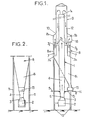
- the installation shown in the figures comprises as main element a vertical reaction column 1 provided at its base with a smoke inlet connector 2 itself connected to a convergent-divergent 3 - 4 for suspending a powdery reactive product.
- This product is brought to the base of the column by a pipe shown diagrammatically at 5 and opening slightly above the neck 6 of the convergent-divergent, whereby an excellent dispersion of the pulverulent product can be ensured in the upward flow of fumes.
- a maximum efficiency of the reactions between the reactive product and the fumes is obtained during the entire time of their ascent in the column, this ascent however being carried out at relatively high speed (of the order of 10 m / s).
- This first separation, carried out between the purified fumes and the largest particles, is provided by a set of cyclones 7.
- these cyclones are housed in the middle part 8m of an envelope 8 which surrounds column 1 on part of its height.
- the entries 7e of the cyclones communicate with the open upper end 1s of the reaction column by a sheath 9 covering the column and the base 9b of which enters the envelope 8.
- the middle part 8m of the envelope, the most of the reaction column 1 and the sheath 9 can consist of coaxial sheet cylinders and are therefore very easy to manufacture and to install.
- the mechanical connections between these different parts can be established by any means, and in particular by welding, riveting or bolting.
- the separating cyclones 7 do not need their own support structure, as in the installations of the prior art, since they are held between column 1 on the one hand, the envelope 8 on the other hand.
- the sheath 9 the base of which is fixed to the entries 7e of the cyclones and which can also be maintained, at 10, at the level of its penetration into the envelope 8.
- the treated fumes and particles of reactive product descend, at lower speed, into the annular space 12 formed between sheath 9 and column 1, the reaction thus being able to continue efficiently until the 7th entrances to cyclones 7; the space 12 also constitutes thermal insulation of the upper part of the column 1 from the outside, the middle part of this column being likewise isolated by the annular space containing the cyclones 7. On thus saves the means of thermal insulation which are usually provided when it is necessary for the fumes to remain hot during their purification.
- centrifugation makes it possible to carry out a first separation between the treated fumes and the larger particles of the product, which fall, through the “material” outlets 7m of the cyclones, into an asymmetrical hopper 81 constituting the lower part of the 'envelope 8.
- the product which is still partially active, can on the one hand be evacuated, at 14, and on the other hand recycled in the column, at 15, the inlet 5 then constituting only one supply of fresh product, compensating for the part discharged at 14, as well as the very fine particles escaping from the "gas" outlets 7g of the cyclones 7, at the same time as the purified fumes.
- the upper part 8s of the casing 8 constitutes around the base 9b of the sheath 9 an outlet manifold for the purified gases, in communication with said outlets 7g of the cyclones 7.
- the outlet 16 of this collector is connected to a filtering device intended to carry out a separation between the purely gaseous part of the fumes and the finest particles of the treatment product and other dust which they contain at their outlet from the cyclones; it may be any suitable filter, for example a fabric filter or an electrostatic precipitator. After which the completely purified fumes can be evacuated to the atmosphere.
Landscapes
- Chemical & Material Sciences (AREA)
- Engineering & Computer Science (AREA)
- Chemical Kinetics & Catalysis (AREA)
- Health & Medical Sciences (AREA)
- Biomedical Technology (AREA)
- Environmental & Geological Engineering (AREA)
- Analytical Chemistry (AREA)
- General Chemical & Material Sciences (AREA)
- Oil, Petroleum & Natural Gas (AREA)
- Physical Or Chemical Processes And Apparatus (AREA)
- Treating Waste Gases (AREA)
- Separation Of Gases By Adsorption (AREA)
- Meat, Egg Or Seafood Products (AREA)
- Devices And Processes Conducted In The Presence Of Fluids And Solid Particles (AREA)
- Filtering Of Dispersed Particles In Gases (AREA)
- General Preparation And Processing Of Foods (AREA)
- Absorbent Articles And Supports Therefor (AREA)
- Medicines Containing Plant Substances (AREA)
- Bakery Products And Manufacturing Methods Therefor (AREA)
- Gas Separation By Absorption (AREA)
- Coloring Foods And Improving Nutritive Qualities (AREA)
- Prevention Of Fouling (AREA)
- Fertilizers (AREA)
- Heat Treatments In General, Especially Conveying And Cooling (AREA)
Claims (6)
dadurch gekennzeichnet,
Priority Applications (1)
| Application Number | Priority Date | Filing Date | Title |
|---|---|---|---|
| AT85402152T ATE36252T1 (de) | 1984-11-07 | 1985-11-07 | Vorrichtung zur behandlung von rauchgasen mit einem pulvrigen material. |
Applications Claiming Priority (2)
| Application Number | Priority Date | Filing Date | Title |
|---|---|---|---|
| FR8416952 | 1984-11-07 | ||
| FR8416952A FR2572659B1 (fr) | 1984-11-07 | 1984-11-07 | Installation pour le traitement de fumees par un produit en poudre |
Publications (2)
| Publication Number | Publication Date |
|---|---|
| EP0181820A1 EP0181820A1 (de) | 1986-05-21 |
| EP0181820B1 true EP0181820B1 (de) | 1988-08-10 |
Family
ID=9309351
Family Applications (1)
| Application Number | Title | Priority Date | Filing Date |
|---|---|---|---|
| EP85402152A Expired EP0181820B1 (de) | 1984-11-07 | 1985-11-07 | Vorrichtung zur Behandlung von Rauchgasen mit einem pulvrigen Material |
Country Status (13)
| Country | Link |
|---|---|
| EP (1) | EP0181820B1 (de) |
| JP (1) | JPS61171525A (de) |
| AT (1) | ATE36252T1 (de) |
| AU (1) | AU4944785A (de) |
| DD (1) | DD238064A5 (de) |
| DE (1) | DE3564197D1 (de) |
| DK (1) | DK511785A (de) |
| ES (1) | ES8608917A1 (de) |
| FI (1) | FI854373L (de) |
| FR (1) | FR2572659B1 (de) |
| HU (1) | HU193136B (de) |
| PT (1) | PT81449B (de) |
| ZA (1) | ZA858583B (de) |
Families Citing this family (4)
| Publication number | Priority date | Publication date | Assignee | Title |
|---|---|---|---|---|
| FR2601602B1 (fr) * | 1986-07-15 | 1990-07-20 | Burion Etienne | Epurateur de fumees polluantes. |
| FR2644560B1 (fr) * | 1989-03-14 | 1994-07-01 | Inst Francais Du Petrole | Procede et dispositif pour bruler des combustibles riches en produits chlores et/ou en metaux lourds |
| FR2748402B1 (fr) * | 1996-05-09 | 1998-06-26 | Inst Francais Du Petrole | Installation de traitement de fumees d'incineration ayant un recyclage interne |
| FR2813655B1 (fr) | 2000-09-01 | 2003-01-03 | Inst Francais Du Petrole | Procede de generation de chaleur permettant une emission reduite des oxydes de soufre et consommation reduite d'absorbant |
Family Cites Families (4)
| Publication number | Priority date | Publication date | Assignee | Title |
|---|---|---|---|---|
| FR2139648B1 (de) * | 1971-05-28 | 1973-08-10 | Prat Daniel Poelman | |
| US3969482A (en) * | 1974-04-25 | 1976-07-13 | Teller Environmental Systems, Inc. | Abatement of high concentrations of acid gas emissions |
| AT372876B (de) * | 1981-11-19 | 1983-11-25 | Oesterr Draukraftwerke | Verfahren und vorrichtung zur rauchgasentschwefelung von kohlefeuerungen nach dem trocken- additivverfahren |
| DE3235559A1 (de) * | 1982-09-25 | 1984-05-24 | Metallgesellschaft Ag, 6000 Frankfurt | Verfahren zur entfernung von schwefeloxiden aus rauchgas |
-
1984
- 1984-11-07 FR FR8416952A patent/FR2572659B1/fr not_active Expired
-
1985
- 1985-11-05 DD DD85282475A patent/DD238064A5/de unknown
- 1985-11-06 HU HU854268A patent/HU193136B/hu unknown
- 1985-11-06 DK DK511785A patent/DK511785A/da not_active Application Discontinuation
- 1985-11-06 FI FI854373A patent/FI854373L/fi not_active IP Right Cessation
- 1985-11-06 JP JP60247292A patent/JPS61171525A/ja active Pending
- 1985-11-07 AU AU49447/85A patent/AU4944785A/en not_active Abandoned
- 1985-11-07 PT PT81449A patent/PT81449B/pt unknown
- 1985-11-07 DE DE8585402152T patent/DE3564197D1/de not_active Expired
- 1985-11-07 EP EP85402152A patent/EP0181820B1/de not_active Expired
- 1985-11-07 AT AT85402152T patent/ATE36252T1/de not_active IP Right Cessation
- 1985-11-07 ZA ZA858583A patent/ZA858583B/xx unknown
- 1985-11-07 ES ES549170A patent/ES8608917A1/es not_active Expired
Also Published As
| Publication number | Publication date |
|---|---|
| HUT40238A (en) | 1986-11-28 |
| AU4944785A (en) | 1986-05-15 |
| PT81449B (fr) | 1987-02-06 |
| FR2572659A1 (fr) | 1986-05-09 |
| DE3564197D1 (en) | 1988-09-15 |
| ZA858583B (en) | 1987-01-28 |
| HU193136B (en) | 1987-08-28 |
| FI854373A7 (fi) | 1986-05-08 |
| ES8608917A1 (es) | 1986-07-16 |
| ES549170A0 (es) | 1986-07-16 |
| ATE36252T1 (de) | 1988-08-15 |
| DD238064A5 (de) | 1986-08-06 |
| FI854373L (fi) | 1986-05-08 |
| JPS61171525A (ja) | 1986-08-02 |
| DK511785D0 (da) | 1985-11-06 |
| PT81449A (fr) | 1985-12-01 |
| EP0181820A1 (de) | 1986-05-21 |
| DK511785A (da) | 1986-05-08 |
| FR2572659B1 (fr) | 1987-01-16 |
| FI854373A0 (fi) | 1985-11-06 |
Similar Documents
| Publication | Publication Date | Title |
|---|---|---|
| FR2525488A1 (fr) | Procede et appareil de filtration d'une suspension | |
| EP0798028B1 (de) | Druckwechseladsorptionsverfahren zur Behandlung eines Gasgemisches | |
| FR2539645A1 (fr) | Tour de lavage pour installation de desulfuration de gaz de fumees | |
| EP0181820A1 (de) | Vorrichtung zur Behandlung von Rauchgasen mit einem pulvrigen Material | |
| FR2460701A1 (fr) | Dispositif de separation de matieres solides dans un courant de liquide | |
| FR2503132A1 (fr) | Procede et installation pour extruder des articles, notamment a partir d'une masse fondue de verre visqueux | |
| FR2726203A1 (fr) | Separateur a flottation centripete, notamment pour le traitement d'effluents aqueux charges | |
| CA1331957C (fr) | Procede de filtration d'air et cyclofiltre a cartouche filtrante pour la mise en oeuvre du procede | |
| FR2539772A1 (fr) | Appareil centrifuge pour l'epuration de suspensions liquides contenant des impuretes solides | |
| FR2884857A1 (fr) | Dispositif a elements de separation par voie inertielle pour le filtrage et l'elimination de particules contenues dans des gaz d'echappement | |
| FR2806321A1 (fr) | Procede et reacteur de traitement d'un gaz au moyen d'un garnissage actif regenerable | |
| FR2631251A1 (fr) | Procede et dispositif pour la filtration de gaz contamines charges en vesicules liquides | |
| EP0698126A1 (de) | Verfahren und Einrichtung zur Wiedergewinnung von mindestens ein Metall aus Industrieabfällen | |
| FR3030861B1 (fr) | Centrale nucleaire | |
| EP0182706B1 (de) | Halbtrockenes Verfahren zum Beseitigen von in Rauchgasen enthaltenen Schadstoffen | |
| FR2587629A1 (fr) | Procede de separation de fines particules de catalyseur, d'une charge hydrocarbonee, par filtration au travers de barrieres minerales et boucle de filtration | |
| FR2514669A1 (fr) | Perfectionnement aux appareils de depoussierage d'air a decolmatage automatique | |
| FR2507914A1 (fr) | Installation de filtrage de gaz chauds | |
| WO1999059920A1 (fr) | Systeme de filtration pour reacteur de conversion d'uf6 en oxyde d'uranium | |
| FR2670136A1 (fr) | Dispositif de separation et de conditionnement de particules entrainees par un gaz. | |
| EP1135206A1 (de) | Verfahren zur wärmebehandlung von feinteiligen feststoffen und vorrichtung zur seiner durchführung | |
| FR3107658A1 (fr) | Procédé de séparation de matériaux polymères d‘un assemblage d’éléments | |
| FR2761979A1 (fr) | Procede et appareil de fabrication d'une fibre optique munie d'un revetement hermetique | |
| EP0682556B1 (de) | Vorrichtung zum filtern von mit teilchen beladenem gas | |
| FR2481783A1 (de) |
Legal Events
| Date | Code | Title | Description |
|---|---|---|---|
| PUAI | Public reference made under article 153(3) epc to a published international application that has entered the european phase |
Free format text: ORIGINAL CODE: 0009012 |
|
| AK | Designated contracting states |
Kind code of ref document: A1 Designated state(s): AT BE CH DE GB IT LI NL SE |
|
| RAP1 | Party data changed (applicant data changed or rights of an application transferred) |
Owner name: AIR INDUSTRIE ENVIRONNEMENT |
|
| 17P | Request for examination filed |
Effective date: 19861103 |
|
| RAP1 | Party data changed (applicant data changed or rights of an application transferred) |
Owner name: SYPRIM AIR INDUSTRIE ENVIRONNEMENT |
|
| 17Q | First examination report despatched |
Effective date: 19871209 |
|
| GRAA | (expected) grant |
Free format text: ORIGINAL CODE: 0009210 |
|
| AK | Designated contracting states |
Kind code of ref document: B1 Designated state(s): AT BE CH DE GB IT LI NL SE |
|
| PG25 | Lapsed in a contracting state [announced via postgrant information from national office to epo] |
Ref country code: SE Effective date: 19880810 Ref country code: AT Effective date: 19880810 |
|
| REF | Corresponds to: |
Ref document number: 36252 Country of ref document: AT Date of ref document: 19880815 Kind code of ref document: T |
|
| ITF | It: translation for a ep patent filed | ||
| GBT | Gb: translation of ep patent filed (gb section 77(6)(a)/1977) | ||
| REF | Corresponds to: |
Ref document number: 3564197 Country of ref document: DE Date of ref document: 19880915 |
|
| PG25 | Lapsed in a contracting state [announced via postgrant information from national office to epo] |
Ref country code: LI Effective date: 19881130 Ref country code: CH Effective date: 19881130 |
|
| PLBE | No opposition filed within time limit |
Free format text: ORIGINAL CODE: 0009261 |
|
| STAA | Information on the status of an ep patent application or granted ep patent |
Free format text: STATUS: NO OPPOSITION FILED WITHIN TIME LIMIT |
|
| REG | Reference to a national code |
Ref country code: CH Ref legal event code: PL |
|
| 26N | No opposition filed | ||
| ITTA | It: last paid annual fee | ||
| NLT1 | Nl: modifications of names registered in virtue of documents presented to the patent office pursuant to art. 16 a, paragraph 1 |
Owner name: PROCEDAIR SA |
|
| PGFP | Annual fee paid to national office [announced via postgrant information from national office to epo] |
Ref country code: NL Payment date: 19991021 Year of fee payment: 15 |
|
| PGFP | Annual fee paid to national office [announced via postgrant information from national office to epo] |
Ref country code: DE Payment date: 19991115 Year of fee payment: 15 |
|
| PG25 | Lapsed in a contracting state [announced via postgrant information from national office to epo] |
Ref country code: NL Free format text: LAPSE BECAUSE OF NON-PAYMENT OF DUE FEES Effective date: 20010601 |
|
| NLV4 | Nl: lapsed or anulled due to non-payment of the annual fee |
Effective date: 20010601 |
|
| PG25 | Lapsed in a contracting state [announced via postgrant information from national office to epo] |
Ref country code: DE Free format text: LAPSE BECAUSE OF NON-PAYMENT OF DUE FEES Effective date: 20010801 |
|
| REG | Reference to a national code |
Ref country code: GB Ref legal event code: IF02 |
|
| PGFP | Annual fee paid to national office [announced via postgrant information from national office to epo] |
Ref country code: GB Payment date: 20031031 Year of fee payment: 19 |
|
| PG25 | Lapsed in a contracting state [announced via postgrant information from national office to epo] |
Ref country code: GB Free format text: LAPSE BECAUSE OF NON-PAYMENT OF DUE FEES Effective date: 20041107 |
|
| PGFP | Annual fee paid to national office [announced via postgrant information from national office to epo] |
Ref country code: BE Payment date: 20041208 Year of fee payment: 20 |
|
| GBPC | Gb: european patent ceased through non-payment of renewal fee |
Effective date: 20041107 |
|
| BE20 | Be: patent expired |
Owner name: S.A. *PROCEDAIR Effective date: 20051107 |
|
| BE20 | Be: patent expired |
Owner name: S.A. *PROCEDAIR Effective date: 20051107 |