EP0181866B1 - Couvercles d'acces pour trous d'hommes - Google Patents
Couvercles d'acces pour trous d'hommes Download PDFInfo
- Publication number
- EP0181866B1 EP0181866B1 EP84903074A EP84903074A EP0181866B1 EP 0181866 B1 EP0181866 B1 EP 0181866B1 EP 84903074 A EP84903074 A EP 84903074A EP 84903074 A EP84903074 A EP 84903074A EP 0181866 B1 EP0181866 B1 EP 0181866B1
- Authority
- EP
- European Patent Office
- Prior art keywords
- members
- corner
- frame
- access cover
- cover according
- Prior art date
- Legal status (The legal status is an assumption and is not a legal conclusion. Google has not performed a legal analysis and makes no representation as to the accuracy of the status listed.)
- Expired
Links
- 229910052751 metal Inorganic materials 0.000 claims abstract description 5
- 239000002184 metal Substances 0.000 claims abstract description 5
- 210000002105 tongue Anatomy 0.000 claims description 8
- 238000007789 sealing Methods 0.000 claims description 4
- 238000005452 bending Methods 0.000 claims description 2
- 239000000463 material Substances 0.000 claims description 2
- 230000002093 peripheral effect Effects 0.000 claims 1
- 238000002788 crimping Methods 0.000 abstract description 9
- XEEYBQQBJWHFJM-UHFFFAOYSA-N Iron Chemical compound [Fe] XEEYBQQBJWHFJM-UHFFFAOYSA-N 0.000 description 8
- 239000004411 aluminium Substances 0.000 description 5
- 229910052782 aluminium Inorganic materials 0.000 description 5
- XAGFODPZIPBFFR-UHFFFAOYSA-N aluminium Chemical compound [Al] XAGFODPZIPBFFR-UHFFFAOYSA-N 0.000 description 5
- 229910052742 iron Inorganic materials 0.000 description 4
- 238000001125 extrusion Methods 0.000 description 2
- 230000002787 reinforcement Effects 0.000 description 2
- 125000006850 spacer group Chemical group 0.000 description 2
- 238000004873 anchoring Methods 0.000 description 1
- 230000015572 biosynthetic process Effects 0.000 description 1
- 238000010276 construction Methods 0.000 description 1
- 238000005755 formation reaction Methods 0.000 description 1
- 239000004570 mortar (masonry) Substances 0.000 description 1
- 229920003023 plastic Polymers 0.000 description 1
- 239000004033 plastic Substances 0.000 description 1
- 230000003014 reinforcing effect Effects 0.000 description 1
Images


Classifications
-
- E—FIXED CONSTRUCTIONS
- E02—HYDRAULIC ENGINEERING; FOUNDATIONS; SOIL SHIFTING
- E02D—FOUNDATIONS; EXCAVATIONS; EMBANKMENTS; UNDERGROUND OR UNDERWATER STRUCTURES
- E02D29/00—Independent underground or underwater structures; Retaining walls
- E02D29/12—Manhole shafts; Other inspection or access chambers; Accessories therefor
- E02D29/14—Covers for manholes or the like; Frames for covers
Definitions
- This invention relates to manhole access covers of the kind in which a removable cover member fits within an outer frame, the cover itself comprising an inner frame with an appropriate filling, each of the inner and outer frames being rectangular and fabricated from a plurality of lengths of angle-sectioned members, mitred at their ends and joined to each other at the corners of the frame.
- GB-A-606014 disclosed a manhole cover generally of this kind.
- the object of the invention is to provide a manhole access cover whose outer and inner frames and particularly the corner joints thereof can be fabricated economically.
- each inner and outer frame comprises a substantially vertical wall formed from vertical limbs of its frame members and a substantially horizontal ledge extending inwardly from the vertical wall and formed from horizontal limbs of its frame members, in that the joint at each corner includes an angular corner member extending around the corner on the vertical wall, and in that the angle sectioned members are crimped to respective corner members by piercing tongues of metal out of the angle sectioned members and bending them against respective walls formed in said corner members.
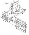
- the manhole access cover has an outer rectangular frame formed from four lengths of angle member 1 formed as aluminium extrusions and joined to each other at the corners of the rectangle.
- Each angle member has a limb 2- which in use of the outer frame extends substantially horizontally and a limb 3 which in use extends substantially vertically; thus the finished frame has a continuous substantially vertical wall and a continuous substantially horizontal ledge extending inwardly from the vertical wall.
- On the outer surfaces of the limbs 2 and 3 are provided a series of ribs which define between them a series of grooves or slots. Some of the ribs are formed with flanges at their free ends which flanges overlie the adjacent grooves to provide, so to speak, captive grooves.
- the grooves 4, 5, 6 and 7 are captive grooves.
- the grooves 4 are provided in the lower part of the vertical wall.
- the corner members 9 have on both their inner and outer surfaces a series of vertical grooves 13, the grooves side walls 14 nearer the ends of the corner members 9 sloping as a ramp to the top of the groove as best seen in Figure 3.
- the crimping tool 12 When the crimping tool 12 is applied it pierces tongues 15 out of the flanges 16 and bends them into the grooves 13 in the corner member 9 to engage against the sloping groove side walls 14. Thus the further the tongues 15 are bent inwards the tighter is the jointing at the corners.
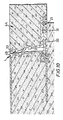
- the grooves provided on the outer surfaces of the limbs 2 and 3 of angle members 1 enable a good keying of the outer frame with the surrounding concrete or mortar when the outer frame is fitted as shown in Figures 8 and 10.
- further keying can be provided by anchoring members 17 ( Figure 10) which have forked ends locating over the flanges 16 and provided with barbs 18 which are trapped behind the flanges 16.
- the inner frame of the manhole access cover has an inner rectangular frame which is closed by concrete or other appropriate filling to form a cover member and which in use fits closely within the outer frame.
- the inner frame is, similarly to the outer frame, formed from four lengths of angle member 21 which are produced as aluminium extrusions.
- Each length of angle member has a limb 22 which in use extends horizontally so that it forms a ledge which rests on the underlying ledge formed by the limbs 2 of the outer frame and a limb 23 which in use extends generally vertically so that it forms a vertical wall which lies adjacent the vertical wall of the outer frame.
- the limbs 23 extend vertically for a distance from their upper edge so that over this region they are close fit in the outer frame and then slope inwardly away from the outer frame, to facilitate lifting of the inner frame out of the outer frame.
- the angle members 21 are formed with ribs on both their inner and outer surfaces as best seen in Figure 4 and which between them define grooves.
- grooves 24 and 25 are provided which correspond in functions to the captive grooves 4 and 5.
- the groove 25 is formed on the inside of the angle member 21.
- the grooves 30 and 31 provide locations for sealing strips to provide a low pressure double gas seal with the outer frame.
- the inner frame is so designed that after assembly it can be crimped in the same crimping machine as used for the outer frame and similarly crimped from the outside of the frame. However, in this crimping operation the crimping tool punches tongues 26 out of the walls of the limbs 23 of the angle members 21 into grooves 13 of the corner members 9.
- each of the limbs 23 is provided with a groove 27 and a vertically extending lower margin 28.
- the bottom of the groove 27 and the margin 28 are verticatty aligned as shown by chain-dotted line 29 in Figure 5 and their spacing and other dimensioning in relation to common reference points on the angle members 2 and 21 being such that they correspond in position as seen by the crimping tool to the flanges 16 overlying the grooves 5 in the angle members 1 as can best be seen from a comparison of Figures 3 and 6.
- the internal ribs on the angle members 21 provide good keys for the concrete or other material used to fill the inner frame as seen in Figures 10 and 11.
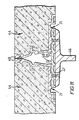
- a groove is provided for receiving a sealing member 33 which seals against the outer frame as best seen in Figures 8 and 10.
- lifting blocks 35 are located in the grooves 25 of the angle members 21. These are slid into place along the grooves 25 prior to joining the angle members 21 together at their corners.
- the lifting blocks 35 are slid sufficiently far along the grooves 25 that they do not interfere with the fitting of the corner members 9.
- the lifting blocks are provided with slot formations 37 for receiving lifting keys shown at 38 in Figure 9.
- the lifting blocks are located by crimped in tongues 51.
- the lifting blocks 35 also in this example provide locations for metal reinforcement of the cover members.
- All the elements of the inner and outer frames so far described can be fabricated from aluminium.
- the reinforcement is preferably of iron and to prevent electrolytic action arising from contact between aluminium and iron the lifting blocks are provided with undercut slots 39 ( Figure 8) in which plastics clips 41 are a snap fit.
- the clips 41 receive in a snap fit iron rods 42.
- the four lifting blocks locate between them two parallel rods 42.
- Further rods 43 can span the two rods 42 and hook over them as shown in Figure 8.
- a reinforcing grid or mesh can be supported by the two rods 42.
- cover members 44 may be supported by a single outer frame.
- Two cover members 44 are shown supported by a single outer frame 45 in Figure 7.
- a long row of cover members 44 may be supported by a single elongated outer frame 45.
- four or more cover members 44 may be supported in two rows by a single outer frame 45.
- FIG. 11 One such spacer member is shown in Figure 11 and comprises a beam 46 which locates at its ends in opposite sides of the outer frame 8 and a platform 47 which locates on the beam 46 and is attached to it.
- the platform supports the adjacent sides of the two inner frames 21 as shown and has two upstanding ribs 48 against which the inner frames can abut to limit sideways movement of the cover members 44 relatively to the outer frame.
- the outer frames are advantageously made of aluminium in contrast to galvanised iron they can be ground without detriment in order to correct for any misalignment with the surrounding floor level.
- the top lips 49 on the outer and inner frames can be made thick enough to allow for such grinding without affecting the strength of the outer frame.
Landscapes
- Engineering & Computer Science (AREA)
- Environmental & Geological Engineering (AREA)
- Life Sciences & Earth Sciences (AREA)
- General Life Sciences & Earth Sciences (AREA)
- Mining & Mineral Resources (AREA)
- Paleontology (AREA)
- Civil Engineering (AREA)
- General Engineering & Computer Science (AREA)
- Structural Engineering (AREA)
- Underground Structures, Protecting, Testing And Restoring Foundations (AREA)
- Sewage (AREA)
- Building Environments (AREA)
Abstract
Claims (10)
Priority Applications (1)
| Application Number | Priority Date | Filing Date | Title |
|---|---|---|---|
| AT84903074T ATE37919T1 (de) | 1983-08-18 | 1984-08-13 | Deckel fuer einsteigschaechte. |
Applications Claiming Priority (2)
| Application Number | Priority Date | Filing Date | Title |
|---|---|---|---|
| GB8322225 | 1983-08-18 | ||
| GB08322225A GB2145138B (en) | 1983-08-18 | 1983-08-18 | Manhole access cover |
Publications (2)
| Publication Number | Publication Date |
|---|---|
| EP0181866A1 EP0181866A1 (fr) | 1986-05-28 |
| EP0181866B1 true EP0181866B1 (fr) | 1988-10-12 |
Family
ID=10547482
Family Applications (1)
| Application Number | Title | Priority Date | Filing Date |
|---|---|---|---|
| EP84903074A Expired EP0181866B1 (fr) | 1983-08-18 | 1984-08-13 | Couvercles d'acces pour trous d'hommes |
Country Status (10)
| Country | Link |
|---|---|
| US (1) | US4637752A (fr) |
| EP (1) | EP0181866B1 (fr) |
| AU (1) | AU562904B2 (fr) |
| CA (1) | CA1210982A (fr) |
| DE (1) | DE3474575D1 (fr) |
| GB (1) | GB2145138B (fr) |
| IE (1) | IE55594B1 (fr) |
| NZ (1) | NZ209230A (fr) |
| WO (1) | WO1985000843A1 (fr) |
| ZA (1) | ZA846369B (fr) |
Cited By (1)
| Publication number | Priority date | Publication date | Assignee | Title |
|---|---|---|---|---|
| DE4213368A1 (de) * | 1992-04-23 | 1993-10-28 | Langenhorst Guenter | Revisionsabdeckung |
Families Citing this family (27)
| Publication number | Priority date | Publication date | Assignee | Title |
|---|---|---|---|---|
| US4867600A (en) * | 1987-07-23 | 1989-09-19 | Bowman Harold M | Polygonal manhole cover support |
| US4963053A (en) * | 1987-07-23 | 1990-10-16 | Bowman Harold M | Multicomponent wales and bases for manhole cover supports |
| CH674387A5 (fr) * | 1987-10-12 | 1990-05-31 | Von Roll Ag | |
| GB2243177B (en) * | 1990-04-17 | 1994-05-25 | Frederick Jones And Son | Support frame for access covers |
| GB9026202D0 (en) * | 1990-12-01 | 1991-01-16 | Centa Antony R | Improvements relating to edging strips for floorcoverings |
| AT396796B (de) * | 1991-11-26 | 1993-11-25 | Gossner Kurt | Schachtabdeckung |
| USD351669S (en) | 1992-09-25 | 1994-10-18 | 3-D Composites Limited | Utility access cover assembly |
| US6007270A (en) | 1993-07-02 | 1999-12-28 | Bowman; Harold M. | Manhole frame assembly |
| US5697729A (en) * | 1993-07-02 | 1997-12-16 | Bowman; Harold M. | Anchor for utility access hole support insert |
| US5628152A (en) * | 1995-08-16 | 1997-05-13 | Bowman; Harold M. | Adjustable manhole cover support with shield |
| GB9402567D0 (en) * | 1994-02-10 | 1994-04-06 | 3 D Composites Ltd | Improvements in access hole cover and frame assemblies |
| US5611640A (en) * | 1994-05-27 | 1997-03-18 | Bowman; Harold M. | Method and apparatus for anchoring a utility grate cover |
| GB9809909D0 (en) | 1998-05-09 | 1998-07-08 | Centa Antony R | Access covers for manholes |
| BE1012394A3 (nl) * | 1998-09-29 | 2000-10-03 | Brochez Alain | Hoekverbinding en werkwijze voor het vervaardigen van dergelijke hoekverbinding, alsmede insteekhoekstukken om zulke hoekverbinding te realiseren. |
| GB2342676A (en) * | 1998-10-14 | 2000-04-19 | Radius Plastics Limited | Underground access chamber |
| FR2800763B1 (fr) * | 1999-11-05 | 2002-08-09 | Sanitrap Technic | Trappe de visite a etancheite renforcee pour une paroi ou pour le sol |
| CH694100A5 (de) * | 2000-03-06 | 2004-07-15 | Von Roll Infranet Sa | Abdeckung für eine Bodenöffnung mit Rahmenteilen mit Steckverbindungsmitteln. |
| GB2417046A (en) | 2004-08-10 | 2006-02-15 | Howe Green Limited | Hinged access cover |
| BE1016453A7 (nl) * | 2005-02-11 | 2006-11-07 | Dvs Eurometaal Nv | Gronddekselprofiel. |
| WO2012135914A1 (fr) * | 2011-04-08 | 2012-10-11 | Pacific Composites Pty Ltd | Cadre pour encercler une fosse et procédé de fabrication |
| DE102012111960A1 (de) * | 2012-12-07 | 2014-06-12 | ACO Severin Ahlmann GmbH & Co Kommanditgesellschaft | Zarge einer Entwässerungsrinne |
| TWI544190B (zh) * | 2013-05-30 | 2016-08-01 | 昱晶能源科技股份有限公司 | 太陽能模組之框架及其l型角連接件 |
| US9249614B1 (en) * | 2014-02-21 | 2016-02-02 | Charles Anthony Mucciolo | Insulation retainer for attic access drop panels |
| US12134886B2 (en) * | 2015-11-25 | 2024-11-05 | Flo-Water, Llc | Water inlet protection system |
| DE102018120623A1 (de) * | 2018-08-23 | 2020-02-27 | ACO Severin Ahlmann GmbH & Co Kommanditgesellschaft | Rahmensystem und Schachtabdeckung |
| DE102020120203B4 (de) * | 2020-07-30 | 2022-09-22 | FAUDI Aviation GmbH | Hydrantendeckel |
| US20250192715A1 (en) * | 2021-10-26 | 2025-06-12 | Origami Solar, Inc. | Methods and Systems for Connecting Solar Panel Frame Components |
Family Cites Families (17)
| Publication number | Priority date | Publication date | Assignee | Title |
|---|---|---|---|---|
| DE532509C (de) * | 1928-03-05 | 1931-08-29 | Vivian Elkington | Rechteckige Schachtabdeckung |
| US2101349A (en) * | 1934-04-07 | 1937-12-07 | Commw Trust Company | Joining lengths of metal |
| GB606014A (en) * | 1945-12-17 | 1948-08-05 | Broad & Company Ltd | Improvements in or relating to manhole or other covers and frames |
| US2877696A (en) * | 1953-06-09 | 1959-03-17 | Dover Eng Works Ltd | Manhole covers and frames |
| GB902650A (en) * | 1960-08-22 | 1962-08-09 | Broads Mfg Company Ltd | Improvements in manhole or like covers and frames |
| CH408372A (de) * | 1964-01-28 | 1966-02-28 | Dista Plastikfabrikation Ag | Distanzierungselement zur Distanzierung von Armierungsstäben von der Verschalung |
| GB1102946A (en) * | 1966-02-22 | 1968-02-14 | Broads Mfg Company Ltd | Improvements in manhole covers and the like |
| US3797194A (en) * | 1971-08-16 | 1974-03-19 | Remington Aluminum Window Corp | Frame construction |
| FR2151698A5 (fr) * | 1971-09-09 | 1973-04-20 | Sambre & Meuse Usines | |
| GB1360790A (en) * | 1971-12-03 | 1974-07-24 | British Aluminium Co Ltd | Connecting elements and frame constructions |
| AU463984B2 (en) * | 1971-12-24 | 1975-08-14 | Clarkson David | Improved manhole cover |
| US3975870A (en) * | 1974-09-05 | 1976-08-24 | Hiromitsu Naka | Floor hatch |
| FR2456169A1 (en) * | 1979-05-11 | 1980-12-05 | Morel Atel Electromec | Rigid plastics gulley grating and frame - are connected in situ by arrowhead frame tongues latching into windows in grating down-stand |
| JPS5744061A (en) * | 1980-08-27 | 1982-03-12 | Naka Tech Lab | Inspection hole |
| GB2092649B (en) * | 1981-01-23 | 1984-07-18 | Brickhouse Dudley Mfg | Manhole covers |
| DK164517C (da) * | 1982-01-20 | 1992-11-23 | Selflevel Covers Jersey Ltd | Daeksel og ramme til en gade- eller nedstigningsbroend |
| CH666101A5 (de) * | 1983-11-17 | 1988-06-30 | Von Roll Ag | Verfahren und abdeckung zum abdichten eines deckels an seiner lagerstelle. |
-
1983
- 1983-08-18 GB GB08322225A patent/GB2145138B/en not_active Expired
-
1984
- 1984-08-13 EP EP84903074A patent/EP0181866B1/fr not_active Expired
- 1984-08-13 AU AU32158/84A patent/AU562904B2/en not_active Ceased
- 1984-08-13 WO PCT/GB1984/000280 patent/WO1985000843A1/fr not_active Ceased
- 1984-08-13 DE DE8484903074T patent/DE3474575D1/de not_active Expired
- 1984-08-13 US US06/726,898 patent/US4637752A/en not_active Expired - Lifetime
- 1984-08-15 NZ NZ209230A patent/NZ209230A/en unknown
- 1984-08-16 IE IE2115/84A patent/IE55594B1/en not_active IP Right Cessation
- 1984-08-17 CA CA000461239A patent/CA1210982A/fr not_active Expired
- 1984-09-16 ZA ZA846369A patent/ZA846369B/xx unknown
Cited By (1)
| Publication number | Priority date | Publication date | Assignee | Title |
|---|---|---|---|---|
| DE4213368A1 (de) * | 1992-04-23 | 1993-10-28 | Langenhorst Guenter | Revisionsabdeckung |
Also Published As
| Publication number | Publication date |
|---|---|
| ZA846369B (en) | 1985-03-27 |
| GB8322225D0 (en) | 1983-09-21 |
| WO1985000843A1 (fr) | 1985-02-28 |
| IE55594B1 (en) | 1990-11-07 |
| US4637752A (en) | 1987-01-20 |
| AU562904B2 (en) | 1987-06-18 |
| GB2145138B (en) | 1986-12-10 |
| CA1210982A (fr) | 1986-09-09 |
| DE3474575D1 (en) | 1988-11-17 |
| EP0181866A1 (fr) | 1986-05-28 |
| NZ209230A (en) | 1987-09-30 |
| IE842115L (en) | 1985-02-18 |
| AU3215884A (en) | 1985-03-12 |
| GB2145138A (en) | 1985-03-20 |
Similar Documents
| Publication | Publication Date | Title |
|---|---|---|
| AU562904B2 (en) | Access covers for manholes | |
| US5473845A (en) | Modular fastening system | |
| US5448865A (en) | Panel interlocking means with stiffener | |
| US4508470A (en) | Manhole/access cover and frame assemblies | |
| CA2041151A1 (fr) | Panneau et methode de construction | |
| US5381632A (en) | Chimney flashing system | |
| EP1989366B1 (fr) | Structure de toiture modulaire pour batiments | |
| US3064273A (en) | Swimming pool | |
| EP0356374A2 (fr) | Panneaux de briques de verre et procédé de fabrication | |
| JPH0224848Y2 (fr) | ||
| US4099356A (en) | Seamed rib panel assembly | |
| US5195789A (en) | Slip lock connector assembly for joining sheet metal ducts | |
| US20030014926A1 (en) | Pitch pocket | |
| US4306394A (en) | Swimming pool | |
| US20040261337A1 (en) | Foundation protector system | |
| GB1581112A (en) | Fixing solar collectors on roofs | |
| US4038793A (en) | Wall structure | |
| KR102375613B1 (ko) | 테두리 결합력이 강화된 전기차 충전기 덮개 | |
| AU669994B2 (en) | Drainage channel | |
| EP0470062A1 (fr) | Méthode et élément pour connecter des murs en bois | |
| GB2044831A (en) | Profile member | |
| JPH0732684Y2 (ja) | カーテンウォールの気密用ガスケット | |
| RU24850U1 (ru) | Профилированная секция для изготовления рамы опалубочного щита | |
| JPH0714534Y2 (ja) | 壁面パネルの防水構造 | |
| JPH0746387Y2 (ja) | 覆蓋装置における蓋体の接合構造 |
Legal Events
| Date | Code | Title | Description |
|---|---|---|---|
| PUAI | Public reference made under article 153(3) epc to a published international application that has entered the european phase |
Free format text: ORIGINAL CODE: 0009012 |
|
| 17P | Request for examination filed |
Effective date: 19860110 |
|
| AK | Designated contracting states |
Kind code of ref document: A1 Designated state(s): AT BE DE FR LU NL SE |
|
| 17Q | First examination report despatched |
Effective date: 19870928 |
|
| GRAA | (expected) grant |
Free format text: ORIGINAL CODE: 0009210 |
|
| AK | Designated contracting states |
Kind code of ref document: B1 Designated state(s): AT BE DE FR LU NL SE |
|
| REF | Corresponds to: |
Ref document number: 37919 Country of ref document: AT Date of ref document: 19881015 Kind code of ref document: T |
|
| REF | Corresponds to: |
Ref document number: 3474575 Country of ref document: DE Date of ref document: 19881117 |
|
| ET | Fr: translation filed | ||
| PLBE | No opposition filed within time limit |
Free format text: ORIGINAL CODE: 0009261 |
|
| STAA | Information on the status of an ep patent application or granted ep patent |
Free format text: STATUS: NO OPPOSITION FILED WITHIN TIME LIMIT |
|
| 26N | No opposition filed | ||
| EPTA | Lu: last paid annual fee | ||
| EAL | Se: european patent in force in sweden |
Ref document number: 84903074.7 |
|
| PGFP | Annual fee paid to national office [announced via postgrant information from national office to epo] |
Ref country code: SE Payment date: 19990804 Year of fee payment: 16 Ref country code: LU Payment date: 19990804 Year of fee payment: 16 |
|
| PGFP | Annual fee paid to national office [announced via postgrant information from national office to epo] |
Ref country code: FR Payment date: 19990810 Year of fee payment: 16 |
|
| PGFP | Annual fee paid to national office [announced via postgrant information from national office to epo] |
Ref country code: AT Payment date: 19990812 Year of fee payment: 16 |
|
| PGFP | Annual fee paid to national office [announced via postgrant information from national office to epo] |
Ref country code: DE Payment date: 19990816 Year of fee payment: 16 |
|
| PGFP | Annual fee paid to national office [announced via postgrant information from national office to epo] |
Ref country code: NL Payment date: 19990830 Year of fee payment: 16 |
|
| PGFP | Annual fee paid to national office [announced via postgrant information from national office to epo] |
Ref country code: BE Payment date: 19991013 Year of fee payment: 16 |
|
| PG25 | Lapsed in a contracting state [announced via postgrant information from national office to epo] |
Ref country code: LU Free format text: LAPSE BECAUSE OF NON-PAYMENT OF DUE FEES Effective date: 20000813 Ref country code: AT Free format text: LAPSE BECAUSE OF NON-PAYMENT OF DUE FEES Effective date: 20000813 |
|
| PG25 | Lapsed in a contracting state [announced via postgrant information from national office to epo] |
Ref country code: SE Free format text: LAPSE BECAUSE OF NON-PAYMENT OF DUE FEES Effective date: 20000814 |
|
| PG25 | Lapsed in a contracting state [announced via postgrant information from national office to epo] |
Ref country code: BE Free format text: LAPSE BECAUSE OF NON-PAYMENT OF DUE FEES Effective date: 20000831 |
|
| BERE | Be: lapsed |
Owner name: CENTA ANTHONY RICHARD Effective date: 20000831 |
|
| PG25 | Lapsed in a contracting state [announced via postgrant information from national office to epo] |
Ref country code: NL Free format text: LAPSE BECAUSE OF NON-PAYMENT OF DUE FEES Effective date: 20010301 |
|
| EUG | Se: european patent has lapsed |
Ref document number: 84903074.7 |
|
| PG25 | Lapsed in a contracting state [announced via postgrant information from national office to epo] |
Ref country code: FR Free format text: LAPSE BECAUSE OF NON-PAYMENT OF DUE FEES Effective date: 20010430 |
|
| NLV4 | Nl: lapsed or anulled due to non-payment of the annual fee |
Effective date: 20010301 |
|
| PG25 | Lapsed in a contracting state [announced via postgrant information from national office to epo] |
Ref country code: DE Free format text: LAPSE BECAUSE OF NON-PAYMENT OF DUE FEES Effective date: 20010501 |
|
| REG | Reference to a national code |
Ref country code: FR Ref legal event code: ST |