EP0181947A1 - Roue porteuse oscillante pour charrues-brabant - Google Patents
Roue porteuse oscillante pour charrues-brabant Download PDFInfo
- Publication number
- EP0181947A1 EP0181947A1 EP84113610A EP84113610A EP0181947A1 EP 0181947 A1 EP0181947 A1 EP 0181947A1 EP 84113610 A EP84113610 A EP 84113610A EP 84113610 A EP84113610 A EP 84113610A EP 0181947 A1 EP0181947 A1 EP 0181947A1
- Authority
- EP
- European Patent Office
- Prior art keywords
- support wheel
- spur
- stem
- pendulum
- axis
- Prior art date
- Legal status (The legal status is an assumption and is not a legal conclusion. Google has not performed a legal analysis and makes no representation as to the accuracy of the status listed.)
- Granted
Links
- 230000002441 reversible effect Effects 0.000 title claims abstract description 6
- 230000005484 gravity Effects 0.000 claims abstract 2
- 230000005540 biological transmission Effects 0.000 claims description 6
- 238000006073 displacement reaction Methods 0.000 claims description 3
- 230000009471 action Effects 0.000 claims description 2
- 230000000694 effects Effects 0.000 abstract description 4
- 239000010902 straw Substances 0.000 description 11
- 230000008901 benefit Effects 0.000 description 4
- 206010010774 Constipation Diseases 0.000 description 2
- 239000002689 soil Substances 0.000 description 2
- 240000008042 Zea mays Species 0.000 description 1
- 235000016383 Zea mays subsp huehuetenangensis Nutrition 0.000 description 1
- 235000002017 Zea mays subsp mays Nutrition 0.000 description 1
- 230000008859 change Effects 0.000 description 1
- 230000008878 coupling Effects 0.000 description 1
- 238000010168 coupling process Methods 0.000 description 1
- 238000005859 coupling reaction Methods 0.000 description 1
- 230000001419 dependent effect Effects 0.000 description 1
- 235000009973 maize Nutrition 0.000 description 1
- 230000004048 modification Effects 0.000 description 1
- 238000012986 modification Methods 0.000 description 1
- 230000000149 penetrating effect Effects 0.000 description 1
- 230000036316 preload Effects 0.000 description 1
- 239000012858 resilient material Substances 0.000 description 1
- 238000004904 shortening Methods 0.000 description 1
- 230000001360 synchronised effect Effects 0.000 description 1
Images



Classifications
-
- A—HUMAN NECESSITIES
- A01—AGRICULTURE; FORESTRY; ANIMAL HUSBANDRY; HUNTING; TRAPPING; FISHING
- A01B—SOIL WORKING IN AGRICULTURE OR FORESTRY; PARTS, DETAILS, OR ACCESSORIES OF AGRICULTURAL MACHINES OR IMPLEMENTS, IN GENERAL
- A01B15/00—Elements, tools, or details of ploughs
-
- A—HUMAN NECESSITIES
- A01—AGRICULTURE; FORESTRY; ANIMAL HUSBANDRY; HUNTING; TRAPPING; FISHING
- A01B—SOIL WORKING IN AGRICULTURE OR FORESTRY; PARTS, DETAILS, OR ACCESSORIES OF AGRICULTURAL MACHINES OR IMPLEMENTS, IN GENERAL
- A01B3/00—Ploughs with fixed plough-shares
- A01B3/36—Ploughs mounted on tractors
- A01B3/40—Alternating ploughs
- A01B3/42—Turn-wrest ploughs
Definitions
- the invention relates to a pendulum support wheel for reversible plows with a spur arranged on the support wheel stem and movable relative to the support wheel stem, according to the preamble of claim 1.
- pendulum support wheels of the aforementioned type are advantageously arranged so that the support wheel handle of the pendulum support wheel swivels in front of the pivot axis of the pendulum support wheel when the plow body is turned.
- the support wheel handle of the pendulum support wheel lies against a stop that determines the working depth.
- This stop can be adjustable in order to make the working depth adjustable.
- the working depth can also be adjusted by making the length of the support wheel shaft variable.
- a disadvantage of swiveling the pendulum support wheel forward is that, especially when driving downhill or on uneven terrain, the pendulum support wheel swings when the plow frame is lowered and when it is put on it can be in front of the pivot axis, so that it dodges forward in an undesirable manner.
- the invention has for its object to form a pendulum support wheel according to the preamble of claim 1 so that a spur can be used with a length that causes a safe return of the pendulum support wheel in its working position under all circumstances, this spur so attached to the support wheel handle is that vegetation or straw does not get caught.
- a spur according to the invention is thus either displaceable and / or pivotable on the support wheel stem, wherein the displacement essentially along the support wheel stem and the pivoting of the spur relative to the support wheel stem is forcibly dependent on the position of the support wheel stem relative to the plow frame.
- Either the relative movement of the support wheel to the support wheel handle or the relative movement of the support wheel handle to the plow frame can be used.
- the spur is advantageously held in its engaging position, that is to say in its position in the longitudinal direction of the support wheel stem, by a strong spring which deflects the spur when it engages in the ground and excludes when decelerating the pendulum support wheel.
- the strength of the spring is kept so large that it only allows the spur to pivot when the support wheel stem of the pendulum support wheel has reached its end stop, ie into its working position. In this position, the pendulum support wheel must also carry at least part of the weight of the plow. As a result, the spring is then so heavily stressed that the spur is deflected backwards upwards, so that vegetation or straw can slide freely under the spur.
- This deflection of the spur under the load of the plow can either be achieved in that the axis of the support wheel is arranged in the rotatably mounted spur, the bearing point of the support wheel axis and the bearing point of the spur being at a distance from one another.
- the spur is provided at its rear end with stops which are arranged laterally at a distance from the longitudinal axis of the spur. These stops of the movably mounted spur act on the plow frame Arranged stops together, so that here also a deflection of the spur occurs when the full plow forces act on the pendulum support wheel.
- the spur is advantageously held in a guide which can be designed as a pocket and is fastened to the support wheel stem. If this pocket is pivotally attached to the support wheel stem, the end of the spur can be articulated directly on the plow frame at a point at a sufficient distance from the pivot axis of the support wheel stem. If, on the other hand, a bag is used that is rigidly attached to the support wheel handle, the end of the spur is connected to the plow frame using a handlebar. In the vertically hanging position the spur then protrudes the farthest downward and is moved with increasing deflection towards its stops, i.e.
- the spur can also be designed to be pivotable. The articulation is also selected so that when the pendulum support wheel swings forward, the spur either maintains its maximum extension length or is extended further, so that a return of the pendulum support wheel is guaranteed with certainty.
- the pivoting of the spur can also take place by means of a gear, the gear between the spur and plow frame being switched on, the pivoting movement of the Jockey wheel handle is used relative to the plow frame to pivot the spur.
- a gear transmission can be used as the transmission, which is reduced to a few teeth and is designed in the form of pins and guides which are arranged on the plow frame and on the support wheel stem.
- a gearbox is also conceivable, which consists of a guide on the plow frame in which a sliding block slides, which actuates a transmission element which adjusts the spur accordingly.
- FIG. 1 an attached reversible plow 1 is shown, which is coupled to a three-point linkage 2, 3 of a tractor 4 in a known manner.
- the plow frame 5 is rotatably mounted in the plow front frame 6.
- a support wheel shaft of a pendulum support wheel 9 is mounted on an axis 7 running approximately transversely to the direction of travel.
- Two stops 11, 12 are attached to a mounting plate 10 which is firmly connected to the frame 5 and can be displaced in elongated holes 13, 14.
- the support wheel stem 8 bears against the stops 11 and 12, respectively.
- the inclination of the support wheel stem 8 to the frame 5 results from the distance between the wheel axle 23 and the position of the stops 11, 12 in the plate 10.
- a spur 18 attached to the support wheel stem extends beyond the outline of the pendulum support wheel 9.
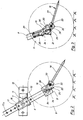
- FIG. 2 shows an embodiment of a pendulum support wheel 15 designed according to the invention in an enlarged view.
- the same parts are provided with the same reference numerals.
- the depth adjustment in this embodiment of the pendulum support wheel 15 is not via adjustable stops 11, 12, but via one in its length adjustable support wheel handle 8.
- the support wheel handle 8 is guided in a pocket 16 which is pivotable about the axis 7 of the support wheel handle.
- a bore 17 is arranged in the pocket 16.
- the support wheel stem 8 also has a row of holes 17a, so that the support wheel stem 8 can be fixed in the pocket 16 by inserting a bolt through the bores 17 and 17a.
- a spur 18 is attached, which is pivotable about an axis 19 which is supported by a fork-shaped end piece 8a of the support wheel stem 8.
- the swivel range of the spur 18 is limited by two stops 20, 21.
- the spur 18 has a fork-shaped part 22 which engages over the end piece 8a and receives the wheel axis 23 of the support wheel 9.
- This wheel axle 23 is arranged below the axle 19.
- the end piece 8 has a pin 24 lying between the axle 19 and the wheel axle which engages between the legs 25 and 26 of a leg spring which is arranged in the fork of the end piece 8a and surrounds the axle 19 in a plurality of turns.
- leg spring also bear against the wheel axle 23 which extends through the fork-shaped part 22.
- the strength of the leg spring is chosen so that the spur 18 is held in its central position by this leg spring, in which it lies in the axial direction of the support wheel stem. When changing the plowing direction, the spur penetrates into the soil. These forces, which decelerate the support wheel in relation to the plow frame, are absorbed by the leg spring without the spur pivoting. Only when the support wheel shaft 8 comes to rest against the stops 11, 12 and thus the weight of the plow on the support wheel 9 does the pretension of the leg spring be exceeded, specifically because of the lever arm caused by the distance between the axis 19 and the wheel axis 23 is obtained.
- the spur then swings out to the rear, as shown in FIG.
- the swivel range of the spur 18 is determined by the Limits 20, 21 limited, which can also be made adjustable.
- the pivoting of the spur 18 is chosen so that vegetation residues or straw can slide past the spur without them getting caught and leading to constipation. Due to the pivotability, namely the forced pivoting of the spur, this can be formed with a much greater length than is the case with non-pivotable spurs or also the case where only a certain spring effect is achieved and which is also in the working position in be forced into a position in which they lie in the longitudinal direction of the support wheel shaft 8.
- the embodiment shown in Fig. 3 corresponds essentially to that of FIG. 2, with the difference that here the spur is formed in two parts and a leaf spring is used.
- the spur 18 here consists of a part 22, which in turn is connected in an articulated manner via the axis 19 to the support wheel stem 8 and carries an upward-facing extension 24.
- the wheel axle 23 of the support wheel 9 is mounted.
- the part 22 has the upward-facing extension 24, on which two leaf springs 25, 26 rest laterally.
- the leaf springs are attached to the support wheel stem 8.
- the downward-facing end 27 of the spur 18 is rotatably mounted on the wheel axle 23 and has a shoulder 28 which projects beyond the wheel axle 23 and carries a pin 29.
- This pin 29 engages in a guide 30 formed in the end of the support wheel stem 8.
- the illustrated pendulum support wheel 31 has a pocket 32 for height adjustment, in which the support wheel stem 8 is displaceable.
- the support wheel shaft 8 is fixed in the pocket 32 in the same way as described with reference to FIG.
- the pocket 32 is in turn rotatably mounted about an axis 7 on the plow frame 5.
- Two end stops 11, 12 serve to determine the working position of the support wheel 9.
- the spur 18 is rotatably mounted on the wheel axis 23 of the support wheel 9 and has a protuberance 33 at its upper end, which forms two stops 34, 35. These stops have a large extent, so that it is ensured that when the support wheel shaft 8 is displaced, they come to rest against the stops 11, 12 of the fastening plate 10.
- a tension spring 36 engages, which has such a preload that the spur 18 is not deflected under normal load by growth, straw and resistance in the ground and only experiences a deflection when the plow weight over the stops 11, 12 on the spur 18 and thus the support wheel stem 8 is transmitted.
- the mode of operation is otherwise the same as that already described with reference to the exemplary embodiments according to FIGS. 2 and 3.
- the support wheel stem 8 is connected directly to the plow frame 5 via an axis 37.
- the height adjustment of the support wheel 9 relative to the plow frame 5 via adjustable stops 11, 12, the efesti- supply plate in the B 10 are arranged, which is connected to the plow frame.
- the spur 18 is guided in a pocket 38 which is attached to the support wheel stem.
- the rear part 39 of the spur 18 extends through the pocket 38 and is connected to the fastening plate 10 via a link 40, the articulation points of the link 40 being designated 41 and 42.
- the spur 18 is displaced in the pocket 38, in such a way that it has a large projection length over the support wheel 9 when it is approximately perpendicular to the plow frame and only a small projection length when the pendulum support wheel 9 is in its working position, ie when the support wheel stem 8 bears against the stops 11, 12.
- This displaceability of the spur relative to the support wheel stem 8 creates a large ground clearance of the spur 18 in the working position of the support wheel stem, so that clogging is avoided with certainty.
- the height adjustment of the support wheel 9 relative to the plow frame 5 is the same as described with reference to the embodiment of FIG. 5.
- the support wheel stem 8 is connected directly to the mounting plate 10 via an axis 37.
- the pocket 38 in which the spur 18 is guided is not rigidly connected to the support wheel stem 8, but is pivotally connected to the support wheel stem 8 about an axis 43.
- the spur 18 slides in this pocket 38 and has an extended end 44 which is articulated to the mounting plate 10 via an axis 45.
- the advantage of training 5 and 6 is that the spur extends deeper towards the ground towards the support wheel stem, the further the pendulum support wheel is pivoted forward.
- the same parts are provided with the same reference numerals.
- the depth adjustment of the support wheel 9 takes place via stops 11, 12 which are adjustably arranged on the plow frame 5.
- the support wheel stem 8 is connected to the fastening plate 10 of the plow frame 5 via an axis 37.
- the spur 18 is formed in two parts, namely that the bearing pin 53 penetrates the support wheel stem 8, the lower fork-shaped end on one side and the upper end 47 of the spur 18 on the other side of the stem 8, both ends with the bearing pin 53 are rotatably connected.
- a gear 46 is used to pivot the spur 18, which is formed from two guides 48, 49 formed at the end 47 of the spur 18 and two pins 50, 51 which are fastened to the fastening plate 10.
- this is a gear coupling of spur 18 and plow frame 5, this gear transmission being reduced to two teeth.
- the pin 50 is inserted deeper into the guide 49, with the spur 18 being pivoted simultaneously with increasing pivoting to the vertical.
- the spur 18 then engages in the ground at a large distance from the support wheel 9, so that the support wheel 9 is forced backwards against the stops 11, 12.
- the guide 48 and the pin 51 serve to guide the spur 18.
- the support wheel stem 8 is in turn guided in a pocket 52.
- This pocket 52 is pivotally attached to the plow frame 5 about an axis 7.
- the adjustment of the support wheel stem 8 in the pocket is carried out as described using the exemplary embodiment in FIG. 2.
- the support wheel stem 8 or the pocket 52 lies in the working position on stops 11, 12 which are firmly connected to the plow frame 5 via the fastening plate 10.
- the support wheel 9 is mounted with the wheel axle 23 in the support wheel stem 8.
- the spur 18 is also pivotable about an axis 53.
- a gear 54 which consists of a link 55 and a link block 56 which is guided in the link 55, and transmission elements which convert the movement of the link block 56 into a rotary movement of the spur 18 about its axis 53 are used to pivot the spur 18 .
- the link 55 is guided around the axis 7, the shape of the link 55 being selected so that the spur protrudes the most over the support wheel 9 when the support wheel stem is hanging vertically, and is only pivoted backwards when the support wheel stem contacts the stops 11, 12 is approaching.
- the sliding block 56 is shown in FIG. 9.
- a receptacle 57 is connected to the sliding block 56 and has a square recess 58.
- a square rod 59 engages in this recess, which in turn is rotatably attached to the pocket 52 and on the support wheel stem 8 via bearing bushes 60, 61.
- the rod 59 is secured against displacement in the longitudinal direction, namely by a pin 62 and a receptacle 63.
- the receptacle 63 has an arm 64 which carries a pin 65.
- a link 66 is pivotally attached, the other end is angled by 90 ° and is articulated at the end 67 of the spur 18.
- the bearing bushes 60 and 61 which receive the rod 59 are adapted to the cross section of the rod 59.
- the bearing bush 61 is provided with a round recess, in which the same also in this area round turned end of the rod 59 engages.
- a locking ring 68 which is placed below the bearing bush 60 on the receptacle 57 penetrating it.
- a scraper is advantageously connected to the spur 18, which serves to clean the support wheels and can be pivoted together with the spur in order to get out of contact with vegetation and straw during plowing. Furthermore, it can also be advantageous to use a wiper alone with a swivel device.
Landscapes
- Life Sciences & Earth Sciences (AREA)
- Engineering & Computer Science (AREA)
- Mechanical Engineering (AREA)
- Soil Sciences (AREA)
- Environmental Sciences (AREA)
- Soil Working Implements (AREA)
- Steroid Compounds (AREA)
- Lifting Devices For Agricultural Implements (AREA)
Priority Applications (4)
| Application Number | Priority Date | Filing Date | Title |
|---|---|---|---|
| EP84113610A EP0181947B1 (fr) | 1984-11-10 | 1984-11-10 | Roue porteuse oscillante pour charrues-brabant |
| AT84113610T ATE39399T1 (de) | 1984-11-10 | 1984-11-10 | Pendelstuetzrad fuer drehpfluege. |
| DE8484113610T DE3475743D1 (en) | 1984-11-10 | 1984-11-10 | Oscillatine depth wheel for a reversible plough |
| EP85105824A EP0166150B1 (fr) | 1984-05-25 | 1985-05-11 | Roue d'appui pivotante |
Applications Claiming Priority (1)
| Application Number | Priority Date | Filing Date | Title |
|---|---|---|---|
| EP84113610A EP0181947B1 (fr) | 1984-11-10 | 1984-11-10 | Roue porteuse oscillante pour charrues-brabant |
Publications (2)
| Publication Number | Publication Date |
|---|---|
| EP0181947A1 true EP0181947A1 (fr) | 1986-05-28 |
| EP0181947B1 EP0181947B1 (fr) | 1988-12-28 |
Family
ID=8192279
Family Applications (1)
| Application Number | Title | Priority Date | Filing Date |
|---|---|---|---|
| EP84113610A Expired EP0181947B1 (fr) | 1984-05-25 | 1984-11-10 | Roue porteuse oscillante pour charrues-brabant |
Country Status (3)
| Country | Link |
|---|---|
| EP (1) | EP0181947B1 (fr) |
| AT (1) | ATE39399T1 (fr) |
| DE (1) | DE3475743D1 (fr) |
Cited By (4)
| Publication number | Priority date | Publication date | Assignee | Title |
|---|---|---|---|---|
| EP0166150A3 (en) * | 1984-05-25 | 1987-12-23 | Rabewerk Heinrich Clausing | Pivotable gauge wheel |
| DE3707857A1 (de) * | 1987-03-11 | 1988-09-22 | Benno Gassner | Anbaudrehpflug |
| WO2016004926A1 (fr) * | 2014-07-09 | 2016-01-14 | Lemken Gmbh & Co Kg | Roue de profondeur orientable destinée à être montée sur le bati d'une charrue |
| WO2020152123A1 (fr) * | 2019-01-22 | 2020-07-30 | Agxeed Holding B.V. | Procédé de labour de terre agricole et tracteur autonome permettant de mettre en œuvre le procédé |
Families Citing this family (1)
| Publication number | Priority date | Publication date | Assignee | Title |
|---|---|---|---|---|
| US8887387B2 (en) | 2009-07-07 | 2014-11-18 | Boston Scientific Neuromodulation Corporation | Methods of manufacture of leads with a radially segmented electrode array |
Citations (3)
| Publication number | Priority date | Publication date | Assignee | Title |
|---|---|---|---|---|
| DE2509455B1 (de) * | 1975-03-05 | 1975-11-13 | Lemken Kg Pflugfab | Stuetzrad fuer Drehpfluege |
| FR2333423A1 (fr) * | 1975-12-03 | 1977-07-01 | Rabewerk Clausing Heinrich | Roue porteuse oscillante pour charrues brabants |
| DE8023453U1 (de) * | 1980-09-03 | 1981-01-08 | Rabewerk Heinrich Clausing, 4515 Bad Essen | Pendelstuetzrad fuer drehpfluege |
-
1984
- 1984-11-10 AT AT84113610T patent/ATE39399T1/de not_active IP Right Cessation
- 1984-11-10 DE DE8484113610T patent/DE3475743D1/de not_active Expired
- 1984-11-10 EP EP84113610A patent/EP0181947B1/fr not_active Expired
Patent Citations (3)
| Publication number | Priority date | Publication date | Assignee | Title |
|---|---|---|---|---|
| DE2509455B1 (de) * | 1975-03-05 | 1975-11-13 | Lemken Kg Pflugfab | Stuetzrad fuer Drehpfluege |
| FR2333423A1 (fr) * | 1975-12-03 | 1977-07-01 | Rabewerk Clausing Heinrich | Roue porteuse oscillante pour charrues brabants |
| DE8023453U1 (de) * | 1980-09-03 | 1981-01-08 | Rabewerk Heinrich Clausing, 4515 Bad Essen | Pendelstuetzrad fuer drehpfluege |
Cited By (6)
| Publication number | Priority date | Publication date | Assignee | Title |
|---|---|---|---|---|
| EP0166150A3 (en) * | 1984-05-25 | 1987-12-23 | Rabewerk Heinrich Clausing | Pivotable gauge wheel |
| DE3707857A1 (de) * | 1987-03-11 | 1988-09-22 | Benno Gassner | Anbaudrehpflug |
| WO2016004926A1 (fr) * | 2014-07-09 | 2016-01-14 | Lemken Gmbh & Co Kg | Roue de profondeur orientable destinée à être montée sur le bati d'une charrue |
| US10172271B2 (en) | 2014-07-09 | 2019-01-08 | Lemken Gmbh & Co Kg | Pivoting support wheel for mounting on a plow frame |
| EA032237B1 (ru) * | 2014-07-09 | 2019-04-30 | Лемкен Гмбх & Ко Кг | Оборотный плуг с поворотным опорным колесом для установки на раме плуга |
| WO2020152123A1 (fr) * | 2019-01-22 | 2020-07-30 | Agxeed Holding B.V. | Procédé de labour de terre agricole et tracteur autonome permettant de mettre en œuvre le procédé |
Also Published As
| Publication number | Publication date |
|---|---|
| DE3475743D1 (en) | 1989-02-02 |
| ATE39399T1 (de) | 1989-01-15 |
| EP0181947B1 (fr) | 1988-12-28 |
Similar Documents
| Publication | Publication Date | Title |
|---|---|---|
| DE2640749C3 (de) | Drillmaschine | |
| DE2759374C2 (de) | Pflug, insbesondere Aufsattelpflug | |
| EP0933013A1 (fr) | Mécanisme de réglage et unité de coupe | |
| DD209711A5 (de) | Bodenbearbeitungsgeraet | |
| EP0062734A1 (fr) | Charrue avec ligne de force de la coupe et point d'attache de traction réglable | |
| EP0081742A1 (fr) | Appareil à travailler la terre déplaçable sur un champ | |
| DE1900762B2 (de) | Selbsttätig rückstellbare Überlastsicherung für ein landwirtschaftliches Bodenbearbeitungswerkzeug | |
| EP0181947B1 (fr) | Roue porteuse oscillante pour charrues-brabant | |
| DE3047675A1 (de) | Halterung fuer zinken von landwirtschaftlich genutzten arbeitsgeraeten, insbesondere zinkenegge | |
| DE3334727C2 (de) | Pflug mit mindestens einem Zusatzwerkzeug zur Tiefenhaltung | |
| DE29600075U1 (de) | Pflug | |
| EP3598882B1 (fr) | Accessoire agricole | |
| DE69305429T2 (de) | Pendelstütz- und Nachlaufrad für Drehpflüge | |
| DE3607691C2 (de) | Landwirtschaftliches Bodenbearbeitungsgerät | |
| DE102005037852A1 (de) | Anbaudrehpflug | |
| DE8432798U1 (de) | Pendelstuetzrad fuer drehpfluege | |
| DE884707C (de) | Scheibenschwenkpflug | |
| DE4031503C2 (de) | Aufsatteldrehpflug | |
| DE102010020431B4 (de) | Mähmaschine | |
| DE3439034A1 (de) | Saeeinrichtung | |
| DE8624526U1 (de) | Anbaupflug | |
| EP0199113A2 (fr) | Corps de charrue additionnel pour charrue brabant | |
| DE1482073C (de) | Mähwerk zum rückwärtigen Anbau an Ackerschlepper | |
| DE521913C (de) | Brabanter Pflug mit selbsttaetigem Ausheben und mechanischer Drehung der Pflugschare | |
| EP0556457B1 (fr) | Charrue réversible attelable ou accrochable |
Legal Events
| Date | Code | Title | Description |
|---|---|---|---|
| PUAI | Public reference made under article 153(3) epc to a published international application that has entered the european phase |
Free format text: ORIGINAL CODE: 0009012 |
|
| 17P | Request for examination filed |
Effective date: 19850928 |
|
| AK | Designated contracting states |
Kind code of ref document: A1 Designated state(s): AT BE CH DE FR GB IT LI NL |
|
| 17Q | First examination report despatched |
Effective date: 19870525 |
|
| ITF | It: translation for a ep patent filed | ||
| GRAA | (expected) grant |
Free format text: ORIGINAL CODE: 0009210 |
|
| AK | Designated contracting states |
Kind code of ref document: B1 Designated state(s): AT BE CH DE FR GB IT LI NL |
|
| PG25 | Lapsed in a contracting state [announced via postgrant information from national office to epo] |
Ref country code: BE Effective date: 19881228 |
|
| REF | Corresponds to: |
Ref document number: 39399 Country of ref document: AT Date of ref document: 19890115 Kind code of ref document: T |
|
| REF | Corresponds to: |
Ref document number: 3475743 Country of ref document: DE Date of ref document: 19890202 |
|
| ET | Fr: translation filed | ||
| GBT | Gb: translation of ep patent filed (gb section 77(6)(a)/1977) | ||
| PLBE | No opposition filed within time limit |
Free format text: ORIGINAL CODE: 0009261 |
|
| STAA | Information on the status of an ep patent application or granted ep patent |
Free format text: STATUS: NO OPPOSITION FILED WITHIN TIME LIMIT |
|
| ITTA | It: last paid annual fee | ||
| 26N | No opposition filed | ||
| REG | Reference to a national code |
Ref country code: CH Ref legal event code: PUE Owner name: RABEWERK GMBH + CO. |
|
| NLS | Nl: assignments of ep-patents |
Owner name: RABEWERK GMBH + CO. TE BAD ESSEN, BONDSREPUBLIEK D |
|
| REG | Reference to a national code |
Ref country code: FR Ref legal event code: CD |
|
| PGFP | Annual fee paid to national office [announced via postgrant information from national office to epo] |
Ref country code: NL Payment date: 19901130 Year of fee payment: 7 |
|
| REG | Reference to a national code |
Ref country code: GB Ref legal event code: 732 |
|
| PG25 | Lapsed in a contracting state [announced via postgrant information from national office to epo] |
Ref country code: NL Effective date: 19920601 |
|
| NLV4 | Nl: lapsed or anulled due to non-payment of the annual fee | ||
| PGFP | Annual fee paid to national office [announced via postgrant information from national office to epo] |
Ref country code: CH Payment date: 19921013 Year of fee payment: 9 |
|
| PGFP | Annual fee paid to national office [announced via postgrant information from national office to epo] |
Ref country code: GB Payment date: 19921102 Year of fee payment: 9 |
|
| PGFP | Annual fee paid to national office [announced via postgrant information from national office to epo] |
Ref country code: AT Payment date: 19921124 Year of fee payment: 9 |
|
| PG25 | Lapsed in a contracting state [announced via postgrant information from national office to epo] |
Ref country code: GB Effective date: 19931110 Ref country code: AT Effective date: 19931110 |
|
| PG25 | Lapsed in a contracting state [announced via postgrant information from national office to epo] |
Ref country code: LI Effective date: 19931130 Ref country code: CH Effective date: 19931130 |
|
| GBPC | Gb: european patent ceased through non-payment of renewal fee |
Effective date: 19931110 |
|
| REG | Reference to a national code |
Ref country code: CH Ref legal event code: PL |
|
| PGFP | Annual fee paid to national office [announced via postgrant information from national office to epo] |
Ref country code: FR Payment date: 19961126 Year of fee payment: 13 |
|
| PGFP | Annual fee paid to national office [announced via postgrant information from national office to epo] |
Ref country code: DE Payment date: 19961230 Year of fee payment: 13 |
|
| PG25 | Lapsed in a contracting state [announced via postgrant information from national office to epo] |
Ref country code: FR Free format text: THE PATENT HAS BEEN ANNULLED BY A DECISION OF A NATIONAL AUTHORITY Effective date: 19971130 |
|
| PG25 | Lapsed in a contracting state [announced via postgrant information from national office to epo] |
Ref country code: DE Free format text: LAPSE BECAUSE OF NON-PAYMENT OF DUE FEES Effective date: 19980801 |
|
| REG | Reference to a national code |
Ref country code: FR Ref legal event code: ST |