EP0181976A1 - Vorrichtung zum Schneiden - Google Patents
Vorrichtung zum Schneiden Download PDFInfo
- Publication number
- EP0181976A1 EP0181976A1 EP19840307946 EP84307946A EP0181976A1 EP 0181976 A1 EP0181976 A1 EP 0181976A1 EP 19840307946 EP19840307946 EP 19840307946 EP 84307946 A EP84307946 A EP 84307946A EP 0181976 A1 EP0181976 A1 EP 0181976A1
- Authority
- EP
- European Patent Office
- Prior art keywords
- cutting
- blade
- suture
- blades
- gripping element
- Prior art date
- Legal status (The legal status is an assumption and is not a legal conclusion. Google has not performed a legal analysis and makes no representation as to the accuracy of the status listed.)
- Granted
Links
- 238000010008 shearing Methods 0.000 claims abstract description 36
- 239000000463 material Substances 0.000 claims abstract description 13
- 230000007423 decrease Effects 0.000 claims description 4
- 230000006378 damage Effects 0.000 claims description 3
- 230000006866 deterioration Effects 0.000 claims description 3
- 230000013011 mating Effects 0.000 claims description 2
- 230000000694 effects Effects 0.000 description 6
- 238000010276 construction Methods 0.000 description 2
- 238000004519 manufacturing process Methods 0.000 description 2
- 230000002028 premature Effects 0.000 description 2
- 229910001220 stainless steel Inorganic materials 0.000 description 2
- 239000010935 stainless steel Substances 0.000 description 2
- 230000003247 decreasing effect Effects 0.000 description 1
- 230000001419 dependent effect Effects 0.000 description 1
- 239000002184 metal Substances 0.000 description 1
- 239000012858 resilient material Substances 0.000 description 1
- 238000005476 soldering Methods 0.000 description 1
- 230000000451 tissue damage Effects 0.000 description 1
- 231100000827 tissue damage Toxicity 0.000 description 1
Images

Classifications
-
- A—HUMAN NECESSITIES
- A61—MEDICAL OR VETERINARY SCIENCE; HYGIENE
- A61B—DIAGNOSIS; SURGERY; IDENTIFICATION
- A61B17/00—Surgical instruments, devices or methods
- A61B17/32—Surgical cutting instruments
- A61B17/3201—Scissors
-
- A—HUMAN NECESSITIES
- A61—MEDICAL OR VETERINARY SCIENCE; HYGIENE
- A61B—DIAGNOSIS; SURGERY; IDENTIFICATION
- A61B17/00—Surgical instruments, devices or methods
- A61B17/04—Surgical instruments, devices or methods for suturing wounds; Holders or packages for needles or suture materials
- A61B17/0467—Instruments for cutting sutures
-
- B—PERFORMING OPERATIONS; TRANSPORTING
- B26—HAND CUTTING TOOLS; CUTTING; SEVERING
- B26B—HAND-HELD CUTTING TOOLS NOT OTHERWISE PROVIDED FOR
- B26B13/00—Hand shears; Scissors
- B26B13/06—Hand shears; Scissors characterised by the shape of the blades
-
- B—PERFORMING OPERATIONS; TRANSPORTING
- B26—HAND CUTTING TOOLS; CUTTING; SEVERING
- B26B—HAND-HELD CUTTING TOOLS NOT OTHERWISE PROVIDED FOR
- B26B13/00—Hand shears; Scissors
- B26B13/12—Hand shears; Scissors characterised by the shape of the handles
- B26B13/14—Hand shears; Scissors characterised by the shape of the handles without gripping bows in the handle
Definitions
- the present invention relates to cutting instruments such as an improved surgical suture remover or scissors.
- the invention provides an instrument that is capable of both cutting and gripping a suture so that a surgeon can, with one hand, cut the stitches and withdraw the cut thread, and that is readily manufacturable at relatively low cost with a high degree of precision and reliability.
- An elongated suture gripping element formed of a resilient material includes a contact area at one end and is attached as by soldering, at its other end to the shearing portion, the contact area being so disposed that as the cutting section and cutting edge are operatively moved toward each other along the cutting plane for shearing contact with a suture, the gripping element is deformed whereby its contact portion is resiliently moved along the cutting plane and substantially perpendicular to its elongation.
- a bend provided in and along the plane of the gripping element adjacent its end connection to the shearing portion advantageously facilitates distribution of the deformation of the gripping element between the bend and the end connection to prevent premature deterioration of the end connection and thereby extend the useful operational life of the instrument.
- GB 942,775 describes disposable surgical scissors made from a single piece of resilient metal strip which is bent to form finger grips wich are parallel and terminate in blades which are pivotally connected together.
- a cutting instrument comprising an elongated strip of yieldable and resiliently flexible material which is bent to form two shanks which are spaced apart and have co-operating cutting blades at their remote ends, which blades are pivotally connected together, characterised in that both of the shanks are twisted substantially 90° in the same direction, whereby the blades are oriented in substantially overlying parallel planes and are capable of shearing action with approximately 0° clearance therebetween.
- a suture remover characterised in that one of the blades has a cutting section, the other blade has a cutting edge, each of the shanks has an integral contact shoulder adjacent the twist for mutual abutment during suture cutting to prevent pivotal movement of said cutting section and cutting edge towards each other beyond a predetermined point and thereby prevent damage to the suture remover, and an elongated suture gripping element on the blade has a contact area and is integrally connected to the blade near the pivot, which gripping element is substantially planar along its elongation and includes a bend connecting the gripping element to the blade so that the gripping element overlays a portion of the blade to which it is integrally connected so that relative movement of the cutting edge and cutting section for shearing contact with a suture causes deformation of the gripping element substantially perpendicular to the elongation of the gripping element as its contact area is resiliently moved along the cutting plane.
- FIG. 1 Another form is a scissors, characterised in that the blades are a cutting blade and shear blade which are pivotably movable toward each other, an abutment shoulder is provided on each of the shanks adjacent to the twist and extending in a plane substantially perpendicular to the plane of the blades for mutual abutment during the operation of the scissors to prevent pivotal movement of said blades toward each other beyond a predetermined point, and the cutting blade and shear blade each have an elongated rib portion which is elevated on the outside of said blade and recesses on the inside of said blade, which rib portions function to bow both cutting blades so that edge-to-edge contact thereof is achieved when the blades are moved towards each other.
- the blades are a cutting blade and shear blade which are pivotably movable toward each other
- an abutment shoulder is provided on each of the shanks adjacent to the twist and extending in a plane substantially perpendicular to the plane of the blades for mutual abutment during the operation of the scissors to prevent
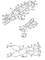
- FIG. 1 One embodiment of a cutting instrument in accordance with the invention, is an improved suture remover designated by the general reference numeral 10, as shown in Figure 1.
- the surgical instrument 10 is formed of a single, initially elongated strip 12 of a resiliently flexible and deformable material such as, by way of example only, stainless steel.
- Strip 12 is provided with a gradual, arcuate central bend 14 substantially midway in its elongation to define a first shank 16 and a second shank 18 disposed in substantially spaced apart relation.
- First shank 16 unitarily carries, on its end remote from central bend 14, an integral blade 20 which includes a cutting section 22 proximate its free end.
- cutting section 22 is provided with an arcuately concave surface or portion 24 and terminates in an end or tip 26 that is preferably somewhat rounded or smoothed to prevent inadvertent tissue damage during operative use of the instrument 10 as will hereinafter become apparent.
- second shank 18 carries, on its end remote from central bend 14, an integral shearing portion 28 which includes a cutting edge 30.
- a rivet 32 or other suitable means pivotally connects blade 20 and shearing portion 28 for relative movement of cutting section 22 and cutting edge 30 toward and away from each other along a cutting plane for shearing contact with a surgical suture to be cut. Movement of cutting section 22 and cutting edge 30 relatively toward each other is accomplished by the application of opposed forces to finger bearing surfaces or portions 34, 36 of first and second shanks 16, 18 respectively, these opposed forces being indicated and represented by the reference arrows 38 in Figure 1. Subsequent return movement of cutting section 22 and cutting edge 30 away from each other is effected by a resilient return urgency imparted by central bend 14 when the surgical user discontinues applying mutually opposed forces 38 to finger bearing surfaces 34, 36.
- the strip of material 12 unitarily forming the surgical instrument 10 may advantageously be provided with cutouts of predetermined configuration and at predetermined locations along shanks 16, 18 and central bend 14 to thereby control the resilient properties and characteristics exhibited.
- central bend 14 includes an elongated slot 40 defined therein and extending along at least a portion of the arc of bend 14. Slot 40 has the effect of decreasing the magnitude of resilient return urgency imparted to suture remover 10 by the central bend with respect to that spring-type urgency which would otherwise be provided in the absence of such a cutout.
- one or a plurality of cutouts or apertures 42 may be predeterminately defined in first and second shanks 16, 18, and particularly in finger bearing surfaces 34, 36, to increase their flexibility.
- cutouts 42 operative use of the instrument 10 as will hereinafter be described requires increased movement of shanks 16, 18 toward each other on application of opposed forces 38 thereto, thus correspondingly increasing the control provided a user of the instrument 10 in effecting a desired degree of relative movment between blade 20 and shearing portion 28.
- each of first and second shanks 16, 18 remote from central bend 14, at which the shanks are integrally and unitarily attached to blade 20 and shearing portion 28, respectively, incorporates a twist 44 of substantially 90° so as to dispose the blade and shearing portion substantially parallel to each other and generally perpendicular to finger bearing surfaces 34, 36 of first and second shanks 16, 18.
- respective contact or abutment shoulders 46, 48 extend from twists 44 and cooperatively interact in the nature of a stop.
- shoulders 46, 48 are correspondingly moved together until, at the end of an operating stroke or suture cutting and gripping closure, the shoulders abuttingly meet or contact.
- This mutual abutment prevents further pivotal movement of cutting section 22 and cutting edge 30 together along the cutting plane irrespective of the continued application of opposed forces 38 to finger bearing surfaces 34, 36. Consequently, damage to the suture remover 10 due to overclosure or like operative abuse is positively prevented by mutual abutment of shoulders 46, 48 at the predetermined point constituting the end of the permissable operating stroke of the instrument.
- gripping element 50 as well as the main body of shearing portion 28, is substantially planar and in the preferred form of instrument 10 gripping element 50 closely overlies a surface area of shearing portion 28 so that they lie in parallel and adjacent planes.
- bend 52 bridgingly extends between said adjacently parallel planes to unitarily connect gripping element 50 with shearing portion 28.
- bend 52 displaces gripping element 50 from the plane of shearing portion 28 to an adjacently parallel and overlying position readily apparent in Figure 2.
- contact area 54 includes an arcuately convex surface or portion 56 for suture-gripping complimentary mating contact or engagement with the correspondingly concave surface 24 of cutting section 22 during operative use of the instrument 10.
- contact area 54, and more particularly surface 56 thereof extends beyond cutting edge 30 so that during an operating stroke suture remover 10 initially grips, and then cuts, the suture.
- An elongated arm 58 extends between contact area 54 and connecting bend 52 of gripping element 50, and is intermediately provided with a narrowed portion 60.
- This widthwise or transverse narrowing of arm 58 in the area 60 has the effect of distributing operative deformation of gripping element 50 predeterminately along its elongation during use of the instrument 10. More particularly, this resilient deformation of gripping element 50 is caused, as a consequence of the presence of narrowed portion 60, to occur primarily at the narrowed portion rather than at the integral connecting bend 52 where such deformation would otherwise primarily take place and, as a consequence, deterioration in the integrity of connecting bend 52 is minimized and the useful operative life of suture remover 10 correspondingly extended.
- Blade 20 is further provided with a protruding dimple or the like extending from its surface adjacently opposing shearing portion 28 for contact with the shearing portion face during a suture cutting and gripping stroke.
- a protruding dimple or the like extending from its surface adjacently opposing shearing portion 28 for contact with the shearing portion face during a suture cutting and gripping stroke.
- contact area 54 of gripping element 50 is resiliently moved or forced along the cutting plane by reason of its continued contact with cutting section 22.
- gripping element 50 is resiliently deformed substantially perpendicular to its elongation. This deformation is primarily concentrated in the arm 58 of gripping element 50 and, more particularly, at its narrowed portion 60.
- the present invention accordingly teaches a surgical suture removal instrument advantageously formed of a single piece of material.
- each and every element and structural feature of the disclosed preferred embodiment is inherently unitary and integral with every other element.
- the relatively small number of requisite manufacturing steps enable this precision instrument to be manufactured at an extremely low production cost.
- the various structural features and elements of the one-piece suture remover cooperatively interact with one another to produce an instrument having operating characteristics and abilities beyond the mere sum of its collected parts.
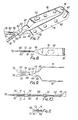
- FIG. 7 to 11 A scissors according to the invention is shown in Figures 7 to 11, the reference numerals applied to like parts shown in Figures 1 to 6 are identical to those in Figures 7 to 11.
- the elongated strip 12 fabricated of a flexible and deformable material, such as stainless steel, is provided with a central bend portion 14 having spaced apart, substantially parallel, finger grip parts 16 and 18 respectively.
- Finger grip 16 at its remote end from the central bend 14, unitarily carries a shank portion 16a, and an integral blade 68 having a cutting surface 70.
- the blade 68 is also provided with an elongated raised rib 72 located substantially along the longitudinal axis of blade 68. It should be noted that the raised portion 72 is also provided with a corresponding recess 74 on the underside of the blade, as seen in Figures 10 and 11.
- Finger grip 16 also is provided with a twist 44, as well as a contact or abutment shoulder 46, and a shank portion 18a.
- Blade 68 at its extreme end, is provided with a rounded tip 76.
- Shank 18 is disposed substantially parallel to shank 16 and also is provided with a twist 44, as well as contact or abutment shoulder 48, which coacts with the oppositely disposed abutment shoulder 46, to form a stop.
- an integral shear blade 78 which is substantially the same configuration as the cutting blade 68, and interacts therewith since the cutting blade is operatively connected to the shear blade by means of a rivet 32.
- the rivet, or other suitable means pivotally connects blade 68 to the shear blade 78. It should be apparent that cutting action of the scissors is achieved by movement of the cutting blade 68 against the shear blade 78 along a cutting plane.
- the blade 78 is provided with an elongated rib 80 substantially similar to the rib 72 on blade 68.
- a dimple 62 is provided on blade 68 between the pivot point 32 and twist 64, having its projection portion inwardly directed towards said shear blade 78 to slightly separate the blades thereby decrease friction between the blade 68 and the shear blade 78, and thus assist in the cutting action.
- the ribs 72 and 78 serve an important function in that they render the tip 76 of the blades inflexible, and they also bow both the cutting blade 68 and the shear blade 78 so that they overlie each other in parallel planes, and edge to edge contact with a substantially 0° clearance is achieved upon moving the cutting blade and the shear blade into contact with each other.
- This arrangement reduces the frictional drag, and consequently makes it easier for small children, and people with limited stength to operate the scissors. For example, a small child's fingers which may not be able to manipulate a standard scissors through its finger rings, will be able to squeeze the resilient finger parts of the present one-piece scissors to thereby easily effect a cutting action on a selected material.
Landscapes
- Health & Medical Sciences (AREA)
- Life Sciences & Earth Sciences (AREA)
- Engineering & Computer Science (AREA)
- Surgery (AREA)
- Molecular Biology (AREA)
- Biomedical Technology (AREA)
- Heart & Thoracic Surgery (AREA)
- Medical Informatics (AREA)
- Nuclear Medicine, Radiotherapy & Molecular Imaging (AREA)
- Animal Behavior & Ethology (AREA)
- General Health & Medical Sciences (AREA)
- Public Health (AREA)
- Veterinary Medicine (AREA)
- Forests & Forestry (AREA)
- Mechanical Engineering (AREA)
- Pathology (AREA)
- Surgical Instruments (AREA)
Priority Applications (2)
| Application Number | Priority Date | Filing Date | Title |
|---|---|---|---|
| EP19840307946 EP0181976B1 (de) | 1984-11-15 | 1984-11-15 | Vorrichtung zum Schneiden |
| DE8484307946T DE3485061D1 (de) | 1984-11-15 | 1984-11-15 | Vorrichtung zum schneiden. |
Applications Claiming Priority (1)
| Application Number | Priority Date | Filing Date | Title |
|---|---|---|---|
| EP19840307946 EP0181976B1 (de) | 1984-11-15 | 1984-11-15 | Vorrichtung zum Schneiden |
Publications (2)
| Publication Number | Publication Date |
|---|---|
| EP0181976A1 true EP0181976A1 (de) | 1986-05-28 |
| EP0181976B1 EP0181976B1 (de) | 1991-09-11 |
Family
ID=8192813
Family Applications (1)
| Application Number | Title | Priority Date | Filing Date |
|---|---|---|---|
| EP19840307946 Expired EP0181976B1 (de) | 1984-11-15 | 1984-11-15 | Vorrichtung zum Schneiden |
Country Status (2)
| Country | Link |
|---|---|
| EP (1) | EP0181976B1 (de) |
| DE (1) | DE3485061D1 (de) |
Cited By (10)
| Publication number | Priority date | Publication date | Assignee | Title |
|---|---|---|---|---|
| DE4215987A1 (de) * | 1992-05-14 | 1993-11-18 | Heiss Josef Medizintech | Medizinisches Instrument |
| EP0589454A3 (en) * | 1992-09-23 | 1994-08-24 | United States Surgical Corp | Endoscopic surgical instrument |
| US5486189A (en) * | 1990-10-05 | 1996-01-23 | United States Surgical Corporation | Endoscopic surgical instrument |
| RU2157118C2 (ru) * | 1998-02-24 | 2000-10-10 | Кондратюк Георгий Константинович | Ножницы |
| EP1616527A2 (de) * | 2004-07-12 | 2006-01-18 | Jeffrey I. Lasner | Griffe und Schäfte für Scheren und Zangen |
| ITRE20090021A1 (it) * | 2009-03-12 | 2010-09-13 | Thd Spa | Dispositivo per la legatura elastica di tessuti |
| CN105476691A (zh) * | 2016-01-28 | 2016-04-13 | 苏州瑞华医院有限公司 | 骨科显微线剪 |
| CN106821459A (zh) * | 2017-03-10 | 2017-06-13 | 上海市第十人民医院 | 人工韧带夹持切割器 |
| CN112153943A (zh) * | 2018-05-23 | 2020-12-29 | 施托尔茨阿姆马克有限责任公司 | 医疗仪器 |
| CN116250878A (zh) * | 2021-12-10 | 2023-06-13 | 苏州微创骨科医疗工具有限公司 | 剪线器械 |
Citations (7)
| Publication number | Priority date | Publication date | Assignee | Title |
|---|---|---|---|---|
| DE402695C (de) * | 1924-09-22 | Zeno Neuschaefer | Schere | |
| US2134265A (en) * | 1936-05-14 | 1938-10-25 | Joseph E Rosenfeld | Peritoneal divider |
| US2865099A (en) * | 1956-07-03 | 1958-12-23 | Robert C Blackwood | Scissor instrument |
| GB942775A (en) * | 1961-03-31 | 1963-11-27 | Johnson & Johnson | Scissors |
| US3987542A (en) * | 1975-08-22 | 1976-10-26 | Visco Luigi P | Scissors |
| US4133107A (en) * | 1976-07-07 | 1979-01-09 | Donald Eugene Vogel | Tool and method for making the same |
| US4246698A (en) * | 1979-07-20 | 1981-01-27 | Laschal Instruments Corp. | Suture remover |
-
1984
- 1984-11-15 DE DE8484307946T patent/DE3485061D1/de not_active Expired - Fee Related
- 1984-11-15 EP EP19840307946 patent/EP0181976B1/de not_active Expired
Patent Citations (7)
| Publication number | Priority date | Publication date | Assignee | Title |
|---|---|---|---|---|
| DE402695C (de) * | 1924-09-22 | Zeno Neuschaefer | Schere | |
| US2134265A (en) * | 1936-05-14 | 1938-10-25 | Joseph E Rosenfeld | Peritoneal divider |
| US2865099A (en) * | 1956-07-03 | 1958-12-23 | Robert C Blackwood | Scissor instrument |
| GB942775A (en) * | 1961-03-31 | 1963-11-27 | Johnson & Johnson | Scissors |
| US3987542A (en) * | 1975-08-22 | 1976-10-26 | Visco Luigi P | Scissors |
| US4133107A (en) * | 1976-07-07 | 1979-01-09 | Donald Eugene Vogel | Tool and method for making the same |
| US4246698A (en) * | 1979-07-20 | 1981-01-27 | Laschal Instruments Corp. | Suture remover |
Cited By (14)
| Publication number | Priority date | Publication date | Assignee | Title |
|---|---|---|---|---|
| US5486189A (en) * | 1990-10-05 | 1996-01-23 | United States Surgical Corporation | Endoscopic surgical instrument |
| DE4215987A1 (de) * | 1992-05-14 | 1993-11-18 | Heiss Josef Medizintech | Medizinisches Instrument |
| EP0589454A3 (en) * | 1992-09-23 | 1994-08-24 | United States Surgical Corp | Endoscopic surgical instrument |
| RU2157118C2 (ru) * | 1998-02-24 | 2000-10-10 | Кондратюк Георгий Константинович | Ножницы |
| EP1616527A2 (de) * | 2004-07-12 | 2006-01-18 | Jeffrey I. Lasner | Griffe und Schäfte für Scheren und Zangen |
| EP2228021A1 (de) * | 2009-03-12 | 2010-09-15 | THD S.p.A. | Vorrichtung zur elastischen Ligatur von Geweben |
| ITRE20090021A1 (it) * | 2009-03-12 | 2010-09-13 | Thd Spa | Dispositivo per la legatura elastica di tessuti |
| US8308742B2 (en) | 2009-03-12 | 2012-11-13 | Thd S.P.A. | Device for elastic ligature of tissues |
| CN105476691A (zh) * | 2016-01-28 | 2016-04-13 | 苏州瑞华医院有限公司 | 骨科显微线剪 |
| CN106821459A (zh) * | 2017-03-10 | 2017-06-13 | 上海市第十人民医院 | 人工韧带夹持切割器 |
| CN106821459B (zh) * | 2017-03-10 | 2023-05-30 | 上海市第十人民医院 | 人工韧带夹持切割器 |
| US20210213599A1 (en) * | 2018-03-23 | 2021-07-15 | Storz Am Mark Gmbh | Medical Instrument |
| CN112153943A (zh) * | 2018-05-23 | 2020-12-29 | 施托尔茨阿姆马克有限责任公司 | 医疗仪器 |
| CN116250878A (zh) * | 2021-12-10 | 2023-06-13 | 苏州微创骨科医疗工具有限公司 | 剪线器械 |
Also Published As
| Publication number | Publication date |
|---|---|
| EP0181976B1 (de) | 1991-09-11 |
| DE3485061D1 (de) | 1991-10-17 |
Similar Documents
| Publication | Publication Date | Title |
|---|---|---|
| US4527331A (en) | Suture remover and continuous band scissors | |
| US6592603B2 (en) | Manually adjustable scissors or forceps | |
| US4246698A (en) | Suture remover | |
| US4505274A (en) | Suture clip | |
| EP0181976A1 (de) | Vorrichtung zum Schneiden | |
| US4212305A (en) | Disposable forceps | |
| US4444187A (en) | Miniature surgical clip for clamping small blood vessels in brain surgery and the like | |
| KR100553021B1 (ko) | 손톱깎기 | |
| US4805876A (en) | Surgical staple remover | |
| JP2008529700A (ja) | 鋏の或いは鋏に関する改良 | |
| US4605020A (en) | Comb | |
| US3003236A (en) | Cutter | |
| US5047037A (en) | Suture removing instrument | |
| US20040118251A1 (en) | Wire stripper | |
| US3287751A (en) | Plier-type cutting and gripping tool | |
| US2755692A (en) | Wire crimping pliers for orthodontists and for general use | |
| CA1236967A (en) | Cutting device | |
| GB2159087A (en) | A cutting instrument | |
| US3266493A (en) | Combination surgical instrument for cutting and removing sutures | |
| US4031624A (en) | Extraction forceps for upper molars | |
| US2801467A (en) | Scissors for cutting sheet metal | |
| CN105636750A (zh) | 剪刀 | |
| CN116196166A (zh) | 一种眼科白内障手术专用撕囊针及其使用方法 | |
| KR200288444Y1 (ko) | 손톱깎이 | |
| CN212233498U (zh) | 一种鹰嘴剪 |
Legal Events
| Date | Code | Title | Description |
|---|---|---|---|
| PUAI | Public reference made under article 153(3) epc to a published international application that has entered the european phase |
Free format text: ORIGINAL CODE: 0009012 |
|
| AK | Designated contracting states |
Kind code of ref document: A1 Designated state(s): DE FR IT |
|
| 17P | Request for examination filed |
Effective date: 19861125 |
|
| 17Q | First examination report despatched |
Effective date: 19890123 |
|
| GRAA | (expected) grant |
Free format text: ORIGINAL CODE: 0009210 |
|
| RAP1 | Party data changed (applicant data changed or rights of an application transferred) |
Owner name: LASCHAL SURGICAL, INC. |
|
| RIN1 | Information on inventor provided before grant (corrected) |
Inventor name: ALEIXO, FRANCISCO Inventor name: LASNER, JEFFREY |
|
| AK | Designated contracting states |
Kind code of ref document: B1 Designated state(s): DE FR IT |
|
| PG25 | Lapsed in a contracting state [announced via postgrant information from national office to epo] |
Ref country code: IT Free format text: LAPSE BECAUSE OF FAILURE TO SUBMIT A TRANSLATION OF THE DESCRIPTION OR TO PAY THE FEE WITHIN THE PRESCRIBED TIME-LIMIT;WARNING: LAPSES OF ITALIAN PATENTS WITH EFFECTIVE DATE BEFORE 2007 MAY HAVE OCCURRED AT ANY TIME BEFORE 2007. THE CORRECT EFFECTIVE DATE MAY BE DIFFERENT FROM THE ONE RECORDED. Effective date: 19910911 |
|
| REF | Corresponds to: |
Ref document number: 3485061 Country of ref document: DE Date of ref document: 19911017 |
|
| EN | Fr: translation not filed | ||
| PG25 | Lapsed in a contracting state [announced via postgrant information from national office to epo] |
Ref country code: FR Effective date: 19920131 |
|
| PLBE | No opposition filed within time limit |
Free format text: ORIGINAL CODE: 0009261 |
|
| STAA | Information on the status of an ep patent application or granted ep patent |
Free format text: STATUS: NO OPPOSITION FILED WITHIN TIME LIMIT |
|
| PG25 | Lapsed in a contracting state [announced via postgrant information from national office to epo] |
Ref country code: DE Effective date: 19920801 |
|
| 26N | No opposition filed | ||
| REG | Reference to a national code |
Ref country code: FR Ref legal event code: ST |