EP0181991A2 - Dispositif de connexion pour tube-image - Google Patents
Dispositif de connexion pour tube-image Download PDFInfo
- Publication number
- EP0181991A2 EP0181991A2 EP85100253A EP85100253A EP0181991A2 EP 0181991 A2 EP0181991 A2 EP 0181991A2 EP 85100253 A EP85100253 A EP 85100253A EP 85100253 A EP85100253 A EP 85100253A EP 0181991 A2 EP0181991 A2 EP 0181991A2
- Authority
- EP
- European Patent Office
- Prior art keywords
- focus
- picture tube
- tube holder
- chamber
- voltage regulator
- Prior art date
- Legal status (The legal status is an assumption and is not a legal conclusion. Google has not performed a legal analysis and makes no representation as to the accuracy of the status listed.)
- Granted
Links
Images

Classifications
-
- H—ELECTRICITY
- H01—ELECTRIC ELEMENTS
- H01R—ELECTRICALLY-CONDUCTIVE CONNECTIONS; STRUCTURAL ASSOCIATIONS OF A PLURALITY OF MUTUALLY-INSULATED ELECTRICAL CONNECTING ELEMENTS; COUPLING DEVICES; CURRENT COLLECTORS
- H01R33/00—Coupling devices specially adapted for supporting apparatus and having one part acting as a holder providing support and electrical connection via a counterpart which is structurally associated with the apparatus, e.g. lamp holders; Separate parts thereof
- H01R33/74—Devices having four or more poles, e.g. holders for compact fluorescent lamps
- H01R33/76—Holders with sockets, clips, or analogous contacts adapted for axially-sliding engagement with parallely-arranged pins, blades, or analogous contacts on counterpart, e.g. electronic tube socket
- H01R33/7607—Holders with sockets, clips, or analogous contacts adapted for axially-sliding engagement with parallely-arranged pins, blades, or analogous contacts on counterpart, e.g. electronic tube socket the parallel terminal pins having a circular disposition
- H01R33/7614—Holders with sockets, clips, or analogous contacts adapted for axially-sliding engagement with parallely-arranged pins, blades, or analogous contacts on counterpart, e.g. electronic tube socket the parallel terminal pins having a circular disposition the terminals being connected to individual wires
- H01R33/7628—Holders with sockets, clips, or analogous contacts adapted for axially-sliding engagement with parallely-arranged pins, blades, or analogous contacts on counterpart, e.g. electronic tube socket the parallel terminal pins having a circular disposition the terminals being connected to individual wires the wires being connected using solder
-
- H—ELECTRICITY
- H01—ELECTRIC ELEMENTS
- H01J—ELECTRIC DISCHARGE TUBES OR DISCHARGE LAMPS
- H01J29/00—Details of cathode-ray tubes or of electron-beam tubes of the types covered by group H01J31/00
- H01J29/92—Means forming part of the tube for the purpose of providing electrical connection to it
Definitions
- the invention relates to a picture tube holder with a contact spring chamber and a focus chamber connected to the contact spring for the focus voltage.
- a picture tube socket - sometimes also called a picture tube connection base - to make the electrical connections for the picture tube.
- the picture tube holder has several contact springs in a contact spring chamber, and when the picture tube holder is pushed onto the end of the picture tube, the pins of the picture tube located there come into contact with the contact springs.
- the picture tube holder itself is located on or on a picture tube connection plate, which is a small printed circuit board which, in addition to the picture tube holder, also carries electrical (protective) resistors and often also the video output stage.
- Focus voltage and an S chirmgitterhard needed.
- the latter defines the operating point of the picture tube, while the focus voltage is responsible for the focusing of the electron beam and thus for the image sharpness.
- This new and surprising measure which can be implemented in a simple manner, makes it possible to provide the focus voltage regulator as an integrated component of the picture tube holder. This offers significant advantages.
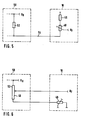
- an expedient embodiment of the invention provides the use of a series resistor, so that the focus voltage is attacked on a series circuit comprising the series resistor and the focus voltage regulator.
- the focus voltage regulator can be made relatively small, so that it can be accommodated in any case within the focus chamber.
- the series resistor mentioned can be accommodated within a pocket provided on the side of the focus chamber.
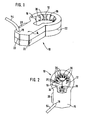
- a center line 22 indicates that the picture tube holder 10 is composed of an upper and a lower half and is welded in the region of the center line 22, for example by ultrasound.
- the entire picture tube holder 10 consists of a plastic, three ribs 25 (cf. FIG. 2) being provided on the chamber floor 24 for reasons of injection technology.
- This spark gap is produced between a focus electrode 34 electrically connected to the focus contact spring - that is to say with the focus voltage - and a spark electrode 40 connected to ground.
- FIG. 5 shows a solution comparable to that of FIG. 4, with the difference that here the focus voltage U F is tapped directly at the focus voltage regulator 48.
Landscapes
- Details Of Television Scanning (AREA)
- Connecting Device With Holders (AREA)
- Tubes (AREA)
Priority Applications (1)
| Application Number | Priority Date | Filing Date | Title |
|---|---|---|---|
| AT85100253T ATE47935T1 (de) | 1984-11-10 | 1985-01-12 | Bildroehrenfassung. |
Applications Claiming Priority (2)
| Application Number | Priority Date | Filing Date | Title |
|---|---|---|---|
| DE3441153 | 1984-11-10 | ||
| DE19843441153 DE3441153A1 (de) | 1984-11-10 | 1984-11-10 | Bildroehrenfassung |
Publications (3)
| Publication Number | Publication Date |
|---|---|
| EP0181991A2 true EP0181991A2 (fr) | 1986-05-28 |
| EP0181991A3 EP0181991A3 (en) | 1987-11-19 |
| EP0181991B1 EP0181991B1 (fr) | 1989-11-08 |
Family
ID=6250008
Family Applications (1)
| Application Number | Title | Priority Date | Filing Date |
|---|---|---|---|
| EP85100253A Expired EP0181991B1 (fr) | 1984-11-10 | 1985-01-12 | Dispositif de connexion pour tube-image |
Country Status (4)
| Country | Link |
|---|---|
| EP (1) | EP0181991B1 (fr) |
| JP (1) | JPS61118986A (fr) |
| AT (1) | ATE47935T1 (fr) |
| DE (2) | DE3441153A1 (fr) |
Family Cites Families (4)
| Publication number | Priority date | Publication date | Assignee | Title |
|---|---|---|---|---|
| US3553727A (en) * | 1969-12-16 | 1971-01-05 | Connector Corp | Kinescope socket with spark gap |
| US4378511A (en) * | 1980-07-28 | 1983-03-29 | American Plasticraft Company | Tube socket assembly with corona disrupter |
| GB2084434B (en) * | 1980-09-16 | 1984-03-28 | Murata Manufacturing Co | A cathode-ray tube socket substrate |
| US4402037A (en) * | 1980-09-17 | 1983-08-30 | Murata Manufacturing Co., Ltd. | Cathode-ray tube socket substrate |
-
1984
- 1984-11-10 DE DE19843441153 patent/DE3441153A1/de not_active Ceased
-
1985
- 1985-01-12 EP EP85100253A patent/EP0181991B1/fr not_active Expired
- 1985-01-12 AT AT85100253T patent/ATE47935T1/de not_active IP Right Cessation
- 1985-01-12 DE DE8585100253T patent/DE3574203D1/de not_active Expired
- 1985-11-06 JP JP60247313A patent/JPS61118986A/ja active Pending
Also Published As
| Publication number | Publication date |
|---|---|
| DE3441153A1 (de) | 1986-05-15 |
| DE3574203D1 (en) | 1989-12-14 |
| JPS61118986A (ja) | 1986-06-06 |
| ATE47935T1 (de) | 1989-11-15 |
| EP0181991A3 (en) | 1987-11-19 |
| EP0181991B1 (fr) | 1989-11-08 |
Similar Documents
| Publication | Publication Date | Title |
|---|---|---|
| DE69732171T2 (de) | Lastschalter mit einem Leistungsschalterblock mit Bearbeitungs-Modul, Kalibrierungs-Modul und Anzeige-Modul | |
| DE2724939B2 (de) | Schaltgerät, insbesondere elektronisches, berührungslos arbeitendes Schaltgerät | |
| DE2943861A1 (de) | Hochfrequenzgeraet oder -baugruppe | |
| DE69114628T2 (de) | Rücklauftransistor. | |
| EP0181991B1 (fr) | Dispositif de connexion pour tube-image | |
| DE2939266A1 (de) | Baueinheit aus einem relais und einer auf einer schaltungsplatte angeordneten schaltungsanordnung | |
| DE3126349A1 (de) | Zwischen objektiv und kamerakoerper einfuegbarer konverter fuer photographische kameras | |
| DE2840115A1 (de) | Schaltanordnung fuer eine elektromagnetische fokussier-bildaufnahmeroehre | |
| DE8432993U1 (de) | Bildröhrenfassung | |
| DE2855844C2 (de) | Schaltung für einen Verstärker mit einem Feldeffekttransistor | |
| DE2002013A1 (de) | Impulslichtempfaenger mit Gleichlichtkompensation | |
| EP0556633B1 (fr) | Transformateurs de lignes pour récepteurs de télévision | |
| DE2839222C2 (de) | Schaltung zum optischen Zünden einer Thyristoreinrichtung | |
| EP0209074B1 (fr) | Douille pour un tube à rayons cathodiques | |
| DE2461464A1 (de) | Elektrotechnisches geraet, vorzugsweise zeitrelais | |
| DE1513211A1 (de) | Gleichspannungsregler | |
| EP0035758B1 (fr) | Circuit pour la production de tensions d'alimentation destinées aux tubes images d'appareils de télévision | |
| DE3009075C2 (de) | Schaltungsanordnung zur Erzeugung von Versorgunsspannungen für Bildröhren von Fernsehgeräten | |
| DE4200664C2 (de) | Bauteil zum Erzeugen der Fokussierspannung in einem Fernsehempfänger | |
| DE2020698C3 (de) | Kanalwähler von Fernsehempfangsgeräten | |
| DE962980C (de) | Veraenderbares Potentiometer zur Amplitudenregelung von Signalen eines breiten Frequenzbandes | |
| DE3700818A1 (de) | Konstanthalter mit doppelfunktion | |
| DE3539037A1 (de) | Steckspule fuer elektronische zwecke | |
| EP0024341A1 (fr) | Dispositif de circuit pour la réception de signaux à courant continu dans les installations télégraphiques et les installations de transmission de données | |
| DE3035124A1 (de) | Roehrenfassung fuer eine kathodenstrahlroehre |
Legal Events
| Date | Code | Title | Description |
|---|---|---|---|
| PUAI | Public reference made under article 153(3) epc to a published international application that has entered the european phase |
Free format text: ORIGINAL CODE: 0009012 |
|
| AK | Designated contracting states |
Kind code of ref document: A2 Designated state(s): AT CH DE FR GB IT LI SE |
|
| PUAL | Search report despatched |
Free format text: ORIGINAL CODE: 0009013 |
|
| AK | Designated contracting states |
Kind code of ref document: A3 Designated state(s): AT CH DE FR GB IT LI SE |
|
| 17P | Request for examination filed |
Effective date: 19871008 |
|
| 17Q | First examination report despatched |
Effective date: 19881019 |
|
| GRAA | (expected) grant |
Free format text: ORIGINAL CODE: 0009210 |
|
| AK | Designated contracting states |
Kind code of ref document: B1 Designated state(s): AT CH DE FR GB IT LI SE |
|
| REF | Corresponds to: |
Ref document number: 47935 Country of ref document: AT Date of ref document: 19891115 Kind code of ref document: T |
|
| PGFP | Annual fee paid to national office [announced via postgrant information from national office to epo] |
Ref country code: SE Payment date: 19891117 Year of fee payment: 6 |
|
| GBT | Gb: translation of ep patent filed (gb section 77(6)(a)/1977) | ||
| REF | Corresponds to: |
Ref document number: 3574203 Country of ref document: DE Date of ref document: 19891214 |
|
| ET | Fr: translation filed | ||
| PGFP | Annual fee paid to national office [announced via postgrant information from national office to epo] |
Ref country code: FR Payment date: 19891229 Year of fee payment: 6 |
|
| PGFP | Annual fee paid to national office [announced via postgrant information from national office to epo] |
Ref country code: AT Payment date: 19900123 Year of fee payment: 6 |
|
| ITF | It: translation for a ep patent filed | ||
| ITTA | It: last paid annual fee | ||
| PGFP | Annual fee paid to national office [announced via postgrant information from national office to epo] |
Ref country code: GB Payment date: 19900131 Year of fee payment: 6 |
|
| PGFP | Annual fee paid to national office [announced via postgrant information from national office to epo] |
Ref country code: DE Payment date: 19900228 Year of fee payment: 6 |
|
| PGFP | Annual fee paid to national office [announced via postgrant information from national office to epo] |
Ref country code: CH Payment date: 19900418 Year of fee payment: 6 |
|
| PLBE | No opposition filed within time limit |
Free format text: ORIGINAL CODE: 0009261 |
|
| STAA | Information on the status of an ep patent application or granted ep patent |
Free format text: STATUS: NO OPPOSITION FILED WITHIN TIME LIMIT |
|
| 26N | No opposition filed | ||
| PG25 | Lapsed in a contracting state [announced via postgrant information from national office to epo] |
Ref country code: GB Effective date: 19910112 Ref country code: AT Effective date: 19910112 |
|
| PG25 | Lapsed in a contracting state [announced via postgrant information from national office to epo] |
Ref country code: SE Effective date: 19910113 |
|
| PG25 | Lapsed in a contracting state [announced via postgrant information from national office to epo] |
Ref country code: LI Effective date: 19910131 Ref country code: CH Effective date: 19910131 |
|
| GBPC | Gb: european patent ceased through non-payment of renewal fee | ||
| PG25 | Lapsed in a contracting state [announced via postgrant information from national office to epo] |
Ref country code: FR Effective date: 19910930 |
|
| REG | Reference to a national code |
Ref country code: CH Ref legal event code: PL |
|
| PG25 | Lapsed in a contracting state [announced via postgrant information from national office to epo] |
Ref country code: DE Effective date: 19911001 |
|
| REG | Reference to a national code |
Ref country code: FR Ref legal event code: ST |
|
| EUG | Se: european patent has lapsed |
Ref document number: 85100253.5 Effective date: 19910910 |