EP0182003A2 - Cross-roll straightening machine with more than two straightening rolls - Google Patents
Cross-roll straightening machine with more than two straightening rolls Download PDFInfo
- Publication number
- EP0182003A2 EP0182003A2 EP85108802A EP85108802A EP0182003A2 EP 0182003 A2 EP0182003 A2 EP 0182003A2 EP 85108802 A EP85108802 A EP 85108802A EP 85108802 A EP85108802 A EP 85108802A EP 0182003 A2 EP0182003 A2 EP 0182003A2
- Authority
- EP
- European Patent Office
- Prior art keywords
- straightening
- rollers
- roller
- bending
- roll
- Prior art date
- Legal status (The legal status is an assumption and is not a legal conclusion. Google has not performed a legal analysis and makes no representation as to the accuracy of the status listed.)
- Withdrawn
Links
- 238000005452 bending Methods 0.000 claims abstract description 55
- 239000000463 material Substances 0.000 claims abstract description 43
- 238000003780 insertion Methods 0.000 description 2
- 230000037431 insertion Effects 0.000 description 2
- 238000000034 method Methods 0.000 description 2
- 230000001419 dependent effect Effects 0.000 description 1
- 238000006073 displacement reaction Methods 0.000 description 1
- 230000000694 effects Effects 0.000 description 1
- 239000002184 metal Substances 0.000 description 1
- 230000035945 sensitivity Effects 0.000 description 1
- 239000013077 target material Substances 0.000 description 1
Images


Classifications
-
- B—PERFORMING OPERATIONS; TRANSPORTING
- B21—MECHANICAL METAL-WORKING WITHOUT ESSENTIALLY REMOVING MATERIAL; PUNCHING METAL
- B21D—WORKING OR PROCESSING OF SHEET METAL OR METAL TUBES, RODS OR PROFILES WITHOUT ESSENTIALLY REMOVING MATERIAL; PUNCHING METAL
- B21D3/00—Straightening or restoring form of metal rods, metal tubes, metal profiles, or specific articles made therefrom, whether or not in combination with sheet metal parts
- B21D3/02—Straightening or restoring form of metal rods, metal tubes, metal profiles, or specific articles made therefrom, whether or not in combination with sheet metal parts by rollers
- B21D3/04—Straightening or restoring form of metal rods, metal tubes, metal profiles, or specific articles made therefrom, whether or not in combination with sheet metal parts by rollers arranged on axes skew to the path of the work
Definitions
- the invention relates to an inclined roller straightening machine with more than two straightening rollers acc. the preamble of claim 1.
- Such straighteners are primarily straighteners for round tubes.
- Tube straightening differs from bar straightening primarily because the permissible forces and surface pressures on the workpiece are smaller during tube straightening. If these forces and surface pressures are exceeded, the pipe bulges or receives permanent markings.
- the outer straightening rollers which are of fundamental importance for straightening, are referred to as support rollers, the middle roller, which, in cooperation with the support rollers, gives the material to be deflected, as a bending roller.
- the remaining straightening roles are leadership roles.
- 10-roll straightening machines which each have a pair of rolls between the straightening roll pairs of the 6-roll straightening machine. With these pairs of rollers, additional straightening is given to the material to be straightened.
- the two roles opposite the 6-roller leveler Additional pairs of rolls of the 10-roll straightening machine, which influence the bending line of the straightening material, are referred to below as "secondary bending rolls".
- secondary bending rolls In the case of the inclined roller straightening machines dealt with here, the number of rollers for the invention makes no fundamental difference.
- 6-roll straightening machines are known, for example, from DE-AS 1 042 350.
- the disadvantage of this solution is that it ignores the sensitivity to high surface pressures, such as occur when bending over a short length and when ovalizing, for pipes with small wall thickness.
- Sensitive pipes that is, pipes with a thin wall, will bulge or show signs of running.
- the invention is based on the object of providing an inclined roller straightening machine for thin-walled tubes which permits strong deflections.
- this object is achieved by the characterizing features of claim 1.
- the angular position of the guide channels, as they are formed by the outer pairs of rollers is adapted to the bending line of the straightening material between the support rollers.
- the surface pressure between the support rollers and the associated guide rollers is reduced because the pipes have a longer contact with the support rollers.
- a lateral offset of the straightening good on the support rollers is largely avoided by the design inclination of the guideway specified by the rollers.
- the specified angular range is intended for leveling material with customary dimensions and corresponds to the inclinations of the leveling material sections following the bending zone, based on the straight pass through the inclined roller leveler.
- the bending force is introduced into a longer section of the straightening material, which on the one hand reduces the surface pressure between the straightening material and the bending roller and on the other hand extends the part of the bending zone in which bends with a plastic deformation component take place. That improves the judging result.
- the roll holders are preferably designed with a predetermined inclination for the roll axes.
- provision can be made to make the inclination of the roll holder adjustable.
- the inlet area of the first straightening roller behind the bending roller on the opposite side of the bending roller is designed as a guide bevel.
- This guide bevel must appear on the workpiece at the operating angle of the roller. It should preferably be a straight line at the operating angle. But a slope of the slope that is slightly curved under the operating angle also serves the same purpose. In the side view of the guide bevel, there is preferably a concave contour.
- An inclination angle is preferably provided between the guide channels formed by the outer pairs of rollers and the straight passage of the workpiece.
- the feature of straightening roll training pursued with claim 8 assumes that the 10-roll straightening machine is operated like a 6-roll straightening machine with two interposed pairs of rolls, each of which provides the straightening good with an additional curvature of the bending line. Based on this, the material to be straightened receives the strongest curvature on the bending roller and a smaller curvature on the two intermediate bending rollers.
- the dimensioning of the roll lengths claimed here prevents the permissible surface pressure values on the straightening goods from being reached prematurely on a single roll, essentially the bending roll, in the above-described mode of operation and thus achieves an optimal utilization of the straightening ability of the straightening goods in the inclined roll straightening machine.
- Claim 9 gives a dimensioning rule for the arrangement / design of the support rollers and the guide rollers assigned to them in a 10-roller straightening machine.
- the feature pursued with claim 10 allows the pulling apart of the support-roller pairs which enables a reduction in the forces required for straightening, because the moments introduced into the straightening material for bending are generated on a longer lever arm.
- Fig. 1 shows the arrangement and design of the rolls 1 ... 6 of a 6-roll straightening machine for tubular, metal straightening material 7.
- the rolls 1, 4; 2, 5; 3, 6; are arranged in pairs opposite to each other.
- the individual pairs of straightening rollers are arranged one behind the other in the direction of travel 8 of the straightening good 7.
- the straightening rolls 1 ... 6 lie with the longitudinal centers, e.g. 37, 38 of their axes of rotation 10, 11 in one plane, the leveling plane.
- the straightening rollers have a concave profile.
- the rollers 1 ... 6 form a guide channel 39 for the straightening material 7 fed axially to the inclined roller straightening machine due to their circumferential profiling and arrangement in pairs (FIG. 4).
- the guide channels - on the feed side and on the discharge side - close an angle alpha of 0.1 in the bending plane, which corresponds to the plane of the drawing, with respect to the longitudinal center 40 of the straightening good 7, as it would be if the straightening good passed straight through the inclined roller straightening machine ° and 10 °.
- This angular range corresponds to the angle of inclination of the bending line at the end of the bending zone for straightening goods with currently customary dimensions and strengths.
- the effective length 19 of the bending roller 5 is at least 30% greater than the effective length 20, 21 of the support rollers 1 and 3, preferably twice as large in the 6-roller straightening machine shown here.
- the embodiment of the invention shown in FIG. 2 forms the inclination of the guide channel for the straightening good 52 by the fact that the straightening rollers 31, 34; 33, 36 are "drilled” obliquely at the angle alpha.
- the machine can otherwise remain unchanged from the conventional design, only the outer pairs of straightening rollers are formed with longitudinal ends 11 ... 18 of different sizes.
- Each of the outer straightening rollers seen in the direction of travel of the straightening material 52, has a "thick” 15 .... 18 and a "thin” longitudinal end 11 .... 14. Within a pair of rollers there are a “thick” and a "thin” longitudinal end at Richtgut 52 opposite. In the same way as the inclination of the entire pair of rollers, this leads to a guide channel for the straightening good 52 which is pivoted by the angle alpha with respect to the straight passage of the straightening good (not shown).
- the bending rollers 5 and 35 in cooperation with the opposite guide rollers 2 and 32, are only able to not yet between the next straightening rolls 3, 6; 33, 36 found to provide the necessary bend.
- the leveling material will, without appropriate guide aids, try to slide past the guide channel formed by the pair of rollers on the outlet side.
- An insertion aid between the "critical" pair of rollers is formed by a guide bevel 22, 23, 51 on the support rollers or secondary bending rollers 3, 33 and 50.
- the end of the leveling material on the inlet side would run if the leveling material deflection was set too large. This is always the role in the axial direction, that is the working direction of the oblique roller leveler acc. Arrow 8, followed by the bending roller on the opposite side of the material to be straightened.
- the 10-roll straightening machine shown in FIG. 3 with the straightening rolls 41... 50 differs from the 6-roll straightening machines described above in terms of the invention in that between the existing three pairs of rolls in the 6-roll Straightener two further pairs of rollers 47, 49 and 48, 50 are inserted and give the workpiece additional bends. This is accompanied by a reverse arrangement of the bending roller 45 and the guide roller 42 opposite it on the material to be straightened.
- the bending roll 45 remains the same Role with the greatest effective length 53.
- the necessary effective lengths 54 of the secondary bending rollers 49 and 50, as well as the effective lengths 55 of the support rollers 41, 43 decrease.
- the angles of inclination beta of the guide channels between the feed and discharge-side outer roller pairs 41, 44 and 43, 46 are smaller compared to the straight passage of the straightening material 30 and preferably measure between 0.3 ° and 3 ° the required length differences between the bending roller 45 and the support rollers 41, 43 are close to the upper limits of the ranges specified.
- the lengths of the secondary bending rollers 49, 50 are preferably between those of the bending roller 45 and the support rollers 41 and 43.
- the rollers 31, 33, 34, 36 are in the direction of the arrows 60, i.e. displaceable in the direction of throughput of the target material 52. They can be moved away from the bending roller and towards it.
- the machines currently on the market are horizontal or axial displacement to the target.
Landscapes
- Engineering & Computer Science (AREA)
- Mechanical Engineering (AREA)
- Wire Processing (AREA)
- Combined Means For Separation Of Solids (AREA)
- Adjustment And Processing Of Grains (AREA)
- Straightening Metal Sheet-Like Bodies (AREA)
Abstract
Gezeigt ist eine Anordnung und Ausbildung für die Rollen (1, 4; 2, 5; 3, 6) einer Schrägrollenrichtmaschine. Diese sind in Durchlaufrichtung (Pfeil 8) des Richtgutes (7) paarweise einander gegenüberliegend und hintereinander angeordnet.
Empfindliche runde, metallische Rohre mit dünner Wand werden, wegen der sonst bestehenden Gefahr bleibender unerwünschter Deformationen und erhöhter Eigenspannungen im Rohr, nur durch Biegen gerichtet. Die Flächenpressungswerte auf das Richtgut werden durch Anpassung der Rollenanordnung und -Ausbildung an die Biegelinie des Richtgutes herabgesetzt. Der von den Auflagerrollen (1, 3) und den zugehörigen Führungsrollen (4, 6) gebildete Führungskanal für das Richtgut (7) wird um einen Winkel (alpha) gegen den geraden Durchlauf (40) geschwenkt und die wirksamen Längen (19, 20, 21) der Rollen (5, 1, 3) werden den Richtkräften angepaßt. Die Biegerolle (5) ist länger ausgebildet als die Auflagerollen (1 und 3). An einzelnen Richtrollen (3) sind Leitschrägen (22) vorgesehen, um das Richtgut (7) auf die stärker gekrümmte Bahn zu bringen. Einige Auflagerrollen sind axial verschieblich.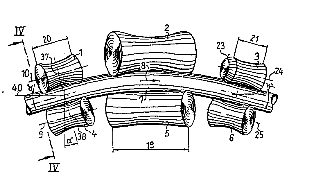
Sensitive round, metallic pipes with a thin wall are only straightened by bending because of the otherwise existing risk of undesired deformations and increased internal stresses in the pipe. The surface pressure values on the leveling material are reduced by adapting the roll arrangement and design to the bending line of the leveling material. The guide channel for the leveling material (7) formed by the support rollers (1, 3) and the associated guide rollers (4, 6) is pivoted by an angle (alpha) against the straight passage (40) and the effective lengths (19, 20, 21) of the rollers (5, 1, 3) are adjusted to the straightening forces. The bending roller (5) is longer than the support rollers (1 and 3). Guide bevels (22) are provided on individual straightening rollers (3) in order to bring the straightening material (7) onto the more curved path. Some support rollers can be moved axially.
Description
Die Erfindung bezieht sich auf eine Schrägrollenrichtmaschine mit mehr als zwei Richtrollen gem. dem Oberbegriff von Anspruch 1. Derartige Richtmaschinen sind in erster Linie Richtmaschinen für runde Rohre. Das Rohrrichten unterscheidet sich vom Stangenrichten vor allem deshalb, weil die zulässigen Kräfte und Flächenpressungen auf das Werkstück beim Rohrrichten kleiner sind. Beim Uberschreiten dieser Kräfte und Flächenpressungen beult das Rohr oder erhält bleibende Markierungen.The invention relates to an inclined roller straightening machine with more than two straightening rollers acc. the preamble of claim 1. Such straighteners are primarily straighteners for round tubes. Tube straightening differs from bar straightening primarily because the permissible forces and surface pressures on the workpiece are smaller during tube straightening. If these forces and surface pressures are exceeded, the pipe bulges or receives permanent markings.
Sechs-Rollen-Richtmaschinen mit 3 Paaren gleicher, konkav ausgebildeter, schräg zur Durchlaufrichtung des Richtgutes angestellter und in Durchlaufrichtung des Richtgutes hintereinander angeordneter, schräg zur Durchlaufrichtung des Richtgutes angestellter Richtrollen sind weit verbreitet. Alle Rollenmitten liegen in einer Ebene, der Biegeebene. Prinzipiell werden für den Richtvorgang nur 3 Rollen benötigt, von jedem Rollenpaar nur eine. Die jeweils gegenüberliegenden Rollen haben Führungsaufgaben, sie sollen ein seitliches Ausscheren des Richtgutes aus der vorgegebenen Bahn vermeiden und das Richtgut beruhigen. Die äußeren Richtrollen, die für das Richten von prinzipieller Bedeutung sind, werden als Auflagerrollen bezeichnet, die mittlere Rolle, die dem Richtgut im Zusammenwirken mit den Auflagerrollen die Durchbiegung verleiht, als Biegerolle. Die übrigen Richtrollen sind Führungsrollen.Six-roll straightening machines with 3 pairs of the same, concave, straightening rolls which are positioned obliquely to the direction of the straightening material and are arranged one behind the other in the direction of flow of the straightening material and are arranged obliquely to the direction of flow of the straightening material are widely used. All roller centers lie in one plane, the bending plane. In principle, only 3 rollers are required for the straightening process, only one of each pair of rollers. The roles opposite each other have management tasks, they are intended to prevent the straightened goods from swerving sideways from the specified path and to calm the straightened goods. The outer straightening rollers, which are of fundamental importance for straightening, are referred to as support rollers, the middle roller, which, in cooperation with the support rollers, gives the material to be deflected, as a bending roller. The remaining straightening roles are leadership roles.
Es sind weiterhin 10-Rollen-Richtmaschinen bekannt, die zwischen den Richtrollenpaaren der 6-Rollen-Richtmaschine jeweils noch ein Rollenpaar aufweisen. Mit diesen Rollenpaaren werden dem Richtgut zusätzliche Biegungen erteilt. Die zwei Rollen der gegenüber der 6-Rollen-Richtmaschine zusätzlichen Rollenpaare der 10-Rollen-Richtmaschine, die die Biegelinie des Richtgutes beeinflussen, werden im weiteren "Neben-Biegerollen" genannt. Bei den hier behandelten Schrägrollenrichtmaschinen macht die Zahl der Rollen für die Erfindung keinen grundsätzlichen Unterschied.10-roll straightening machines are also known which each have a pair of rolls between the straightening roll pairs of the 6-roll straightening machine. With these pairs of rollers, additional straightening is given to the material to be straightened. The two roles opposite the 6-roller leveler Additional pairs of rolls of the 10-roll straightening machine, which influence the bending line of the straightening material, are referred to below as "secondary bending rolls". In the case of the inclined roller straightening machines dealt with here, the number of rollers for the invention makes no fundamental difference.
6-Rollen-Richtmaschinen sind z.B.aus der DE-AS 1 042 350 bekannt. Darüberhinaus ist vorgeschlagen worden, das mittlere Rollenpaar wie bei einer Zwei-Rollen-Richtmaschine auszubilden (DE-OS 2 902 827). Damit sollen kurze abgeknickte Enden von Rohren gerichtet werden. Der Nachteil dieser Lösung ist, daß sie für Rohre mit kleiner Wandstärke deren Empfindlichkeit gegen hohe Flächenpressungen, wie sie beim Biegen auf kurzer Länge und beim Ovalisieren auftreten, außer Acht läßt. Empfindliche Rohre, das sind Rohre mit dünner Wand, werden beulen oder Laufspuren bekommen.6-roll straightening machines are known, for example, from DE-AS 1 042 350. In addition, it has been proposed to design the middle pair of rollers as in a two-roller straightening machine (DE-OS 2 902 827). This is intended to straighten short, bent ends of pipes. The disadvantage of this solution is that it ignores the sensitivity to high surface pressures, such as occur when bending over a short length and when ovalizing, for pipes with small wall thickness. Sensitive pipes, that is, pipes with a thin wall, will bulge or show signs of running.
Der Erfindung liegt demgegenüber die Aufgabe zugrunde, eine Schrägrollenrichtmaschine für dünnwandige Rohre zu schaffen, die starke Durchbiegungen erlaubt.In contrast, the invention is based on the object of providing an inclined roller straightening machine for thin-walled tubes which permits strong deflections.
Diese Aufgabe wird erfindungsgemäß durch die kennzeichnenden Merkmale von Anspruch 1 gelöst. Beim Richten in einer erfindungsgemäßen Schrägrollenrichtmaschine ist die winklige Lage der Führungskanäle, wie sie von den äußeren Rollenpaaren gebildet werden, der Biegelinie des Richtgutes zwischen den Auflagerrollen angepaßt. Dadurch wird die Flächenpressung zwischen den Auflagerrollen und den zugeordneten Führungsrollen herabgesetzt, weil die Rohre eine längere Anlage an den Auflagerrollen haben. Zusätzlich wird ein seitlicher Versatz des Richtgutes an den Auflagerrollen durch die konstruktiv vorgegebene Neigung der von den Rollen vorgegebenen Führungsbahn weitgehend vermieden.According to the invention, this object is achieved by the characterizing features of claim 1. When straightening in an inclined roller straightening machine according to the invention, the angular position of the guide channels, as they are formed by the outer pairs of rollers, is adapted to the bending line of the straightening material between the support rollers. As a result, the surface pressure between the support rollers and the associated guide rollers is reduced because the pipes have a longer contact with the support rollers. In addition, a lateral offset of the straightening good on the support rollers is largely avoided by the design inclination of the guideway specified by the rollers.
Der angegebene Winkelbereich ist für Richtgut mit gebräuchlichen Abmessungen bestimmt und entspricht den Neigungen der Richtgutabschnitte im Anschluß an die Biegezone, bezogen auf den geraden Durchlauf durch die Schrägrollenrichtmaschine .The specified angular range is intended for leveling material with customary dimensions and corresponds to the inclinations of the leveling material sections following the bending zone, based on the straight pass through the inclined roller leveler.
Mit der Vergrößerung der wirksamen Länge der (mittleren) Biegerolle wird die Biegekraft in einen längeren Abschnitt des Richtgutes eingeleitet, wodurch einerseits die Flächenpressung zwischen Richtgut und Biegerolle herabgesetzt wird und andererseits der Teil der Biegezone verlängert, in dem Biegungen mit plastischem Verformungsanteil erfolgen. Das verbessert das Richtergebnis.With the increase in the effective length of the (middle) bending roller, the bending force is introduced into a longer section of the straightening material, which on the one hand reduces the surface pressure between the straightening material and the bending roller and on the other hand extends the part of the bending zone in which bends with a plastic deformation component take place. That improves the judging result.
Mit Anspruch 2 wird eine Ausführungsform der Erfindung verfolgt, die es ermöglicht, mit herkömmlichen, konkaven und im Profil symmetrischen Richtrollen den Effekt des geneigten Führungskanals zu erreichen. Hierzu werden die Rollenhalter vorzugsweise mit einer fest vorgegebenen Neigung für die Rollenachsen ausgebildet. Ergänzend kann vorgesehen sein, die Neigung der Rollenhalter einstellbar zu machen.With claim 2 an embodiment of the invention is pursued, which makes it possible to achieve the effect of the inclined guide channel with conventional, concave and symmetrical straightening rollers. For this purpose, the roll holders are preferably designed with a predetermined inclination for the roll axes. In addition, provision can be made to make the inclination of the roll holder adjustable.
Als Alternative zu Anspruch 2 wird mit Anspruch 3 eine Lösung verfolgt, die von einem insoweit unveränderten Maschinenaufbau ausgeht, wobei jedoch das Rollenprofil beider Rollen, des einlaufseitigen Rollenpaares und des auslaufseitigen Rollenpaares, asymmetrisch ausgebildet ist. Damit wird ebenfalls ein geneigter Führungskanal für das Richtgut auf der Ein- und Auslaufseite der Schrägrollenrichtmaschine erzielt. Die Forderung nach einer großen Anlagelänge zwischen Richtgut und Auflagerrollen ist damit wieder erfüllt.As an alternative to claim 2, a solution is pursued with
Mit dem Merkmal von Anspruch 4 wird erreicht, daß an keiner Stelle im Bereich der Auflagerrollen und in erster Linie im Bereich der Biegerolle vorzeitig die maximale Flächenpressung zwischen Richtgut und Richtrollen erreicht wird.With the feature of
Mit der durch die erfindungsmäße Lösung grundsätzlich möglich gewordenen stärkeren Durchbiegung des Werkstücks geht unter bestimmten Bedingungen, die werkstück- und maschinenabhängig sind, das Problem einher, den Richtgutanfang beim Einlaufen in die Schrägrollenrichtmaschine so zu führen, daß er zuverlässig zwischen das jeweils nächste Rollenpaar findet und nicht seitlich ausschert. Eine Einführhilfe bietet hier das in Anspruch 5 genannte Merkmal. Die Gefahr des Vorbeilaufens des Werkstücks an dem nächsten Rollenpaar besteht in erster Linie hinter dem Rollenpaar, das dem Werkstück die größte Durchbiegung vermitteln soll, da die Biegerolle für die stärkste Ablenkung des Werkstückanfangs sorgt. Deshalb ist der Einlaufbereich der ersten Richtrolle hinter der Biegerolle auf der gegenüberliegenden Seite der Biegerolle als Leitschräge ausgebildet. Diese Leitschräge muß sich dem Werkstück unter dem Betriebswinkel der Rolle darstellen. Bevorzugt soll sie unter dem Betriebswinkel eine Gerade sein. Aber auch ein unter dem Betriebswinkel leicht gekrümmter Verlauf der Schräge erfüllt denselben Zweck. In der Seitenansicht der Leitschräge ergibt sich vorzugsweise eine konkave Kontur.With the stronger deflection of the workpiece, which has fundamentally been made possible by the solution according to the invention, under certain conditions, which are dependent on the workpiece and the machine, there is the problem of guiding the beginning of the leveling material as it enters the inclined roller leveling machine so that it reliably finds between the next pair of rollers and does not veer sideways. An insertion aid offers the feature mentioned in
Diese durch den Rollenkonturbereich bedingte Leitschräge muß sich unter dem Betriebswinkel der Rolle ergeben. Eine Leitschräge ergibt sich je nach Schrägungswinkel unter dem Betriebswinkel auch bereits, wenn die hier betrachtete Auflagerrolle in ihrer Seitenansicht noch einen sich leicht vergrößernden Durchmesser aufweist. Mit Anspruch 6 wird jedoch eine Ausbildung der Erfindung verfolgt, die in der Seitenansicht der Rolle bereits einen zur Einlaufseite sich verjüngenden Längsbereich zeigt.This guide slope caused by the roller contour area must result from the operating angle of the roller. Depending on the helix angle, a guide bevel already occurs at the operating angle if the support roller considered here still has a slightly increasing diameter in its side view. Claim 6, however, pursues an embodiment of the invention which, in the side view of the roller, already shows a longitudinal region which tapers towards the inlet side.
Bevorzugt ist ein Neigungswinkel zwischen den von den äußeren Rollenpaaren gebildeten Führungskanälen und dem geraden Durchlauf des Werkstücks gemäß Anspruch 7 vorgesehen.An inclination angle is preferably provided between the guide channels formed by the outer pairs of rollers and the straight passage of the workpiece.
Das mit Anspruch 8 verfolgte Merkmal der Richtrollenausbildung geht davon aus, daß die 10-Rollen-Richtmaschine betrieben wird wie eine 6-Rollen-Richtmaschine mit zwei zwischengeschalteten Rollenpaaren, die dem Richtgut je eine zusätzliche Krümmung der Biegelinie vermitteln. Davon ausgehend erhält das Richtgut eine stärkste Krümmung an der Biegerolle und je eine kleinere Krümmung an den beiden zwischengeschalteten Neben-Biegerollen. Die hier beanspruchte Bemessung der Rollenlängen verhindert ein vorzeitiges Erreichen der zulässigen Flächenpressungwerte auf das Richtgut an einer einzigen Rolle, im wesentlichen der Biegerolle, bei der vorbeschriebenen Betriebsweise und erreicht somit eine optimale Ausschöpfung der Richtfähigkeit des Richtgutes in der Schrägrollenrichtmaschine.The feature of straightening roll training pursued with claim 8 assumes that the 10-roll straightening machine is operated like a 6-roll straightening machine with two interposed pairs of rolls, each of which provides the straightening good with an additional curvature of the bending line. Based on this, the material to be straightened receives the strongest curvature on the bending roller and a smaller curvature on the two intermediate bending rollers. The dimensioning of the roll lengths claimed here prevents the permissible surface pressure values on the straightening goods from being reached prematurely on a single roll, essentially the bending roll, in the above-described mode of operation and thus achieves an optimal utilization of the straightening ability of the straightening goods in the inclined roll straightening machine.
Anspruch 9 gibt eine Bemessungsregel für die Anordnung/Ausbildung der Auflagerrollen und der ihnen zugeordneten Führungsrollen bei einer 10-Rollen-Richtmaschine.
Das mit Anspruch 10 verfolgte Merkmal erlaubt durch das damit möglich werdende Auseinanderziehen der Auflager-Rollenpaare eine Herabsetzung der für das Richten erforderlichen Kräfte, weil die in das Richtgut zum Biegen eingeleiteten Momente an einem längeren Hebelarm erzeugt werden.The feature pursued with
Die Erfindung wird im einzelnen anhand der Zeichnung näher erläutert. Dabei zeigen:
- Fig. 1: Eine Seitenansicht einer schematisch wiedergegebenen Sechs - Rollen - Richtmaschine
- Fig. 2: Eine Seitenansicht, wie Fig. 1, jedoch mit einer anderen Ausführungsform
- Fig. 3: Eine Seitenansicht einer schematisch wiedergegebenen 10-Rollen-Richtmaschine.
- Fig. 4: eine Ansicht nach Linie IV-IV in Fig. 1, jedoch ohne Werkstück,
- Fig. 1: A side view of a schematically reproduced six-roll straightening machine
- Fig. 2: A side view, like Fig. 1, but with a different embodiment
- Fig. 3: A side view of a schematically reproduced 10-roll straightening machine.
- 4: a view along line IV-IV in FIG. 1, but without a workpiece,
Fig. 1 zeigt die Anordnung und Ausbildung der Rollen 1 .... 6 einer 6-Rollen-Richtmaschine für rohrförmiges, metallisches Richtgut 7. Die Rollen 1, 4; 2, 5; 3, 6; sind paarweise einander gegenüberliegend angeordnet. Die einzelnen Paare von Richtrollen sind in Durchlaufrichtung 8 des Richtgutes 7 hintereinander angeordnet. Die Richtrollen 1 .... 6 liegen mit den Längsmitten, z.B. 37, 38 ihrer Drehachsen 10, 11 in einer Ebene, der Richtebene. Die Richtrollen sind konkav profiliert. Die Rollen 1 .... 6 bilden für das axial der Schrägrollenrichtmaschine zugeführte Richtgut 7 durch ihre Umfangsprofilierung und paarweise Anordnung einen Führungskanal 39 (Fig. 4). Die Führungskanäle -- auf der Zuführ- und auf der Abführseite -schließen in der Biegeebene, die der Zeichenebene entspricht, gegenüber der Längsmitte 40 des Richtgutes 7, wie sie bei geradem Durchlauf des Richtgutes durch die Schrägrollenrichtmaschine wäre, einen Winkel alpha zwischen 0,1° und 10° ein. Dieser Winkelbereich entspricht dem Steigungswinkel der Biegelinie am Ende der Biegezone für Richtgut mit derzeit üblichen Abmessungen und Festigkeiten. Die wirksame Länge 19 der Biegerolle 5 ist um mindestens 30% größer als die wirksame Länge 20, 21 der Auflagerrollen 1 und 3, vorzugsweise bei der hier gezeigten 6-Rollen-Richtmaschine doppelt so groß.Fig. 1 shows the arrangement and design of the rolls 1 ... 6 of a 6-roll straightening machine for tubular, metal straightening material 7. The
In Fig. 1 ist zur Schwenkung des Führungskanales 39 um den Winkel alpha, das ist die Schwenkung gegen die Längsmitte 40 des Richtgutes 7, das Rollenpaar 1, 4 als eine Einheit um den Winkel alpha gegen eine Linie rechtwinklig zur Längsmitte 40 geschwenkt. Dadurch wird das beim Richtprozeß in seinem Längsabschnitt zwischen den zu- und abführseitigen Rollenpaaren gebogene Richtgut 7 im Bereich dieser äußeren Rollenpaare besser und schonender geführt als bei nicht geschwenkter Anordnung der Rollenlängsachsen 9, 10.In Fig. 1 for the pivoting of the
Die in Fig. 2 gezeigte Ausführungsform der Erfindung bildet die Neigung des Führungskanals für das Richtgut 52 dadurch aus, daß die zu- und abführseitigen Richtrollen 31, 34; 33, 36 unter dem Winkel alpha schräg "gebohrt" sind. Die Maschine kann im übrigen gegenüber der herkömmlichen Bauart unverändert bleiben, nur die äußeren Richtrollenpaare werden mit im Durchmesser unterschiedlich großen Längsenden 11 .... 18 ausgebildet. Jede der in Durchlaufrichtung des Richtgutes 52 gesehen äußeren Richtrollen hat ein "dickes" 15 .... 18 und ein "dünnes" Längsende 11 .... 14. Innerhalb eines Rollenpaares liegen sich je ein "dickes" und ein "dünnes" Längsende am Richtgut 52 gegenüber. Das führt in gleicher Weise wie die Neigung des gesamten Rollenpaares zu einem um den Winkel alpha gegenüber dem -- nicht gezeigten -- geraden Durchlauf des Richtgutes verschwenkten Führungskanal für das Richtgut 52.The embodiment of the invention shown in FIG. 2 forms the inclination of the guide channel for the straightening good 52 by the fact that the straightening
Durch die vorbeschriebene Ausbildung und Anordnung der Rollen einer Rollenrichtmaschine wird es möglich, größere Durchbiegungen und und damit bessere Geradheiten von dünnwandigen Rohren zu erzielen, ohne die Oberflächengüte der Rohre zu beeinträchtigen. Mit der stärkeren Durchbiegung ergeben sich, maschinen- und richtgutabhängig, unter Umständen Schwierigkeiten bezüglich der Einführung des Richtgutes in die Schrägrollenrichtmaschine. Diese Schwierigkeiten treten in erster Linie auslaufseitig des Richtrollenpaares mit der Biegerolle bzw. einlaufseitig des folgenden Richtrollenpaares auf. Dem entspricht bei der in den Fig. 1 und 2 gezeigten 6-Rollen-Richtmaschine die Einlaufseite des letzten Rollenpaares. Die Biegerollen 5 und 35, im Zusammenwirken mit den gegenüberliegenden Führungsrollen 2 und 32, sind nur sehr beschränkt in der Lage, dem Richtgutanfang, der noch nicht zwischen die nächsten Richtrollen 3, 6; 33, 36 gefunden hat, die nötige Biegung zu vermitteln. Das Richtgut wird, ohne entsprechende Führungshilfen, versuchen, sich an dem vom auslaufseitigen Rollenpaar gebildeten Führungskanal vorbeizuschieben. Eine Einführhilfe zwischen das "kritische" Rollenpaar bildet eine Leitschräge 22, 23, 51 an den Auflager- oder Neben-Biegerollen 3, 33 und 50. Gegen deren Stirnseiten würde das einlaufseitige Richtgutende bei zu groß eingestellter Richtgutdurchbiegung laufen. Dabei handelt es sich immer um die Rolle, die in axialer Richtung, das ist die Arbeitsrichtung der Schrägrollenrichtmaschine gem. Pfeil 8, auf die Biegerolle auf gegenüberliegender Seite des Richtgutes folgt.The design and arrangement of the rollers of a roller straightening machine described above makes it possible to achieve greater deflections and thus better straightness of thin-walled tubes without impairing the surface quality of the tubes. Depending on the machine and the material to be straightened, the greater deflection may result in difficulties with the introduction of the straightening material into the inclined roller leveler. These difficulties occur primarily on the exit side of the pair of straightening rollers with the bending roller or on the inlet side of the following pair of straightening rollers. In the 6-roll straightening machine shown in FIGS. 1 and 2, this corresponds to the entry side of the last pair of rolls. The bending
Die in Fig. 3 gezeigte 10-Rollen-Richtmaschine mit den Richtrollen 41 .... 50 unterscheidet sich von den zuvor beschriebenen 6-Rollen-Richtmaschinen, was die Erfindung anbetrifft, dadurch, daß zwischen die vorhandenen drei Rollenpaare bei der 6-Rollen-Richtmaschine zwei weitere Rollenpaare 47, 49 und 48, 50 eingeschoben sind und dem Werkstück zusätzliche Biegungen verleihen. Damit geht eine gegenüber der 6-Rollenrichtmaschine umgekehrte Anordnung der Biegerolle 45 und der ihr am Richtgut gegenüberliegenden Führungsrolle 42 einher. Bei der bisher üblichen Betriebsweise dieser 10-Rollen-Richtmaschinen mit der größten Durchbiegung des Richtgutes im Bereich der in der Länqsmitte angeordneten Biegerolle 45 und kleineren, aber auch noch zumindest teilweise plastischen Durchbiegungen im Bereich der Neben-Biegerollen 49 und 50 bleibt die Biegerolle 45 die Rolle mit der größten wirksamen Länge 53. Nach außen hin nehmen die notwendigen wirksamen Längen 54 der Neben-Biegerollen 49 und 50, sowie die wirksamen Längen 55 der Auflagerrollen 41, 43 ab. Durch die Zwischenschaltung der Nebenbiegerollen 49, 50 bei einer 10-Rollen-Richtmaschine werden die Neigungswinkel beta der Führungskanäle zwischen den zu- und abführseitigen äußeren Rollenpaaren 41, 44 und 43, 46 gegenüber dem geraden Durchlauf des Richtgutes 30 kleiner und messen vorzugsweise zwischen 0,3° und 3° Die erforderlichen Längenunterschiede zwischen der Biegerolle 45 und den Auflagerrollen 41, 43 liegen nahe den oberen Grenzen der angegebenen Bereiche. Die Längen der Neben-Biegerollen 49, 50 liegen vorzugsweise zwischen denen der Biegerolle 45 und der Auflagerrollen 41 und 43.The 10-roll straightening machine shown in FIG. 3 with the straightening rolls 41... 50 differs from the 6-roll straightening machines described above in terms of the invention in that between the existing three pairs of rolls in the 6-roll Straightener two further pairs of
Bei der in Fig. 2 gezeigten Rollenanordnung sind die Rollen 31, 33, 34, 36 in Richtung der Pfeile 60, d.h. in Durchlaufrichtung des Richtgutes 52 verschiebbar. Sie können von der Biegerolle weg und auf diese zu verschoben werden. Bei den heute marktüblichen Maschinen handelt es sich dabei um eine horizontale bzw. zum Richtgut axiale Verschiebung.In the roller arrangement shown in Fig. 2, the
-
1 Auflagerrolle 31 Auflagerrolle1
support roller 31 support roller -
2 mittl. Führungsrolle 32 mittl. Führungsrolle2
middle Guide roller 32 middle Leadership role -
3 hintere Auflagerrolle 33 hintere Auflagerrolle3
rear support roller 33 rear support roller -
4 vordere Führungsrolle 34 vordere Führungsrolle4
front guide roller 34 front guide roller -
5 Biegerolle 35 Biegerolle5 bending
roll 35 bending roll -
6 hintere Führungsrolle 36 hintere Führungsrolle6
rear guide roller 36 rear guide roller -
7 Richtgut 37 Längsmitte von 17 leveling
material 37 longitudinal center of 1 - 8 Pfeil(Vorschubrichtung) 38 Längsmitte von 48 arrow (feed direction) 38 longitudinal center of 4
-
9 Längsachse v. Rolle 4 39 Führungskanal9 longitudinal axis v.
Roll 4 39 guide channel -
10 Längsachse v.Rollel 40 Längsmitte10 Longitudinal axis of the
roll 40 Longitudinal center - 11 LE kl.Durchm. v. 31 41 vordere Auflagerrolle11 LE small diam. v. 31 41 front support roller
- 12 LE kl.Durchm. v. 34 42 mittlere Führgsrolle12 LE small diam. v. 34 42 middle guide roller
- 13 LE kl.Durchm. v. 33 43 hintere Auflagerrolle13 LE small diam. v. 33 43 rear support roller
- 14 LE kl.Durchm. v. 36 44 vordere Führungsrolle14 LE small diam. v. 36 44 front guide roller
- 15 LE gr.Durchm. v. 31 45 Biegerolle15 LE large diam. v. 31 45 bending roll
- 16 LE gr.Durchm. v. 34 46 hintere Führungsrolle16 LE large diam. v. 34 46 rear guide roller
- 17 LE gr.Durchm. v. 33 47 Führungsrolle17 LE large diam. v. 33 47 Leadership role
- 18 LE gr.Durchm. v. 36 48 Führungsrolle18 LE large diam. v. 36 48 Leadership role
-
19 wirks. Länge Biegerolle 49 Neben-Biegerolle19 effective. Length of bending
roller 49 secondary bending roller -
20 wirks. Länge Aufl.rolle 50 Nebenbiegerolle20 effective. Length of
reel roll 50 secondary bending roll - 21 wirks. Länge Aufl.rolle 51 Leitschräge21 effective. Length of roller roll 51 guide bevel
- 22 Leitschräge 52 Richtgut22 Guiding slopes 52 Straightening goods
- 23 Leitschräge 53 wirks. Länge v. 4523 guide slopes 53 effective. Length of 45
- 24 geneigte Längsachse v.3 54 wirks. Längen v. 49, 5024 inclined longitudinal axis v.3 54 effective. Lengths from 49, 50
- 25 geneigte Längsachse v.6 55 wirks. Längen v. 41, 4325 inclined longitudinal axis v.6 55 effective. Lengths from 41, 43
-
26 geneigte Längsachse v.41 56 verschobene Rolle 3126 inclined longitudinal axis v.41 56 shifted
roller 31 -
27 geneigte Längsachse v.44 57 verschobene Rolle 3427 inclined longitudinal axis v.44 57 displaced
roller 34 -
28 geneigte Längsachse v.43 58 verschobene Rolle 3328 inclined longitudinal axis v.43 58 displaced
roller 33 -
29 geneigte Längsachse v.46 59 verschobene Rolle 3629 inclined longitudinal axis v.46 59 displaced
roller 36 - 30 Richtgut (Fig.3) 60 Pfeil Versch. Auflagerr.30 Straightening good (Fig. 3) 60 arrow misc. Support
Claims (10)
gekennzeichnet durch die folgenden Merkmale:
characterized by the following features:
Leitschräge (22, 23, 51) ausgebildeten Umfangskonturbereich,5.) Inclined roller straightening machine with more than two straightening rollers, according to claim 1, characterized by the following feature:
Guide bevel (22, 23, 51) formed circumferential contour area,
Applications Claiming Priority (2)
| Application Number | Priority Date | Filing Date | Title |
|---|---|---|---|
| DE3441537 | 1984-11-14 | ||
| DE19843441537 DE3441537A1 (en) | 1984-11-14 | 1984-11-14 | SLOPE ROLLER LEVELING MACHINE WITH MORE THAN 2 ROLLERS |
Publications (2)
| Publication Number | Publication Date |
|---|---|
| EP0182003A2 true EP0182003A2 (en) | 1986-05-28 |
| EP0182003A3 EP0182003A3 (en) | 1987-03-25 |
Family
ID=6250243
Family Applications (1)
| Application Number | Title | Priority Date | Filing Date |
|---|---|---|---|
| EP85108802A Withdrawn EP0182003A3 (en) | 1984-11-14 | 1985-07-13 | Cross-roll straightening machine with more than two straightening rolls |
Country Status (4)
| Country | Link |
|---|---|
| EP (1) | EP0182003A3 (en) |
| JP (1) | JPS61119330A (en) |
| DE (1) | DE3441537A1 (en) |
| HU (1) | HUT41659A (en) |
Cited By (5)
| Publication number | Priority date | Publication date | Assignee | Title |
|---|---|---|---|---|
| EP0431775A3 (en) * | 1989-11-22 | 1991-07-10 | Nkk Corporation | Method of continuous finishing of pipe |
| US20120304724A1 (en) * | 2010-03-29 | 2012-12-06 | Sumitomo Metal Industries, Ltd. | Method for straightening tube and straightening roll |
| CN112317566A (en) * | 2020-11-09 | 2021-02-05 | 天津市热电设计院有限公司 | A short-section pipe shaping device for large-diameter directly buried heating pipes |
| CN114263059A (en) * | 2021-12-01 | 2022-04-01 | 湖南湘钢金属材料科技有限公司 | Elevator wire rope post-deformer |
| EP4015192A3 (en) * | 2020-12-21 | 2022-09-14 | Andrew Turner | An apparatus and method for reducing the curve in a roll of pipe |
Families Citing this family (1)
| Publication number | Priority date | Publication date | Assignee | Title |
|---|---|---|---|---|
| FR2938110B1 (en) * | 2008-11-06 | 2013-02-15 | Areva Nc | METHOD FOR EMPTYING NUCLEAR FUEL TANKS AND MILLING MACHINE BY SHEATH DEFORMATION |
Family Cites Families (3)
| Publication number | Priority date | Publication date | Assignee | Title |
|---|---|---|---|---|
| US2655194A (en) * | 1946-10-31 | 1953-10-13 | Einar W Nilsson | Apparatus for processing round bars and tubes |
| DE2902827C2 (en) * | 1979-01-23 | 1984-05-10 | Mannesmann AG, 4000 Düsseldorf | Cross-roll straightening machine for pipes |
| JPS5744624U (en) * | 1980-08-21 | 1982-03-11 |
-
1984
- 1984-11-14 DE DE19843441537 patent/DE3441537A1/en not_active Withdrawn
-
1985
- 1985-07-13 EP EP85108802A patent/EP0182003A3/en not_active Withdrawn
- 1985-11-05 HU HU425785A patent/HUT41659A/en unknown
- 1985-11-06 JP JP24868085A patent/JPS61119330A/en active Pending
Cited By (9)
| Publication number | Priority date | Publication date | Assignee | Title |
|---|---|---|---|---|
| EP0431775A3 (en) * | 1989-11-22 | 1991-07-10 | Nkk Corporation | Method of continuous finishing of pipe |
| US20120304724A1 (en) * | 2010-03-29 | 2012-12-06 | Sumitomo Metal Industries, Ltd. | Method for straightening tube and straightening roll |
| US8783085B2 (en) * | 2010-03-29 | 2014-07-22 | Nippon Steel & Sumitomo Metal Corporation | Method for straightening tube and straightening roll |
| EP2554287A4 (en) * | 2010-03-29 | 2015-04-29 | Nippon Steel & Sumitomo Metal Corp | REDRESSING ROLL AND METHOD FOR PIPE REPRESSING |
| CN112317566A (en) * | 2020-11-09 | 2021-02-05 | 天津市热电设计院有限公司 | A short-section pipe shaping device for large-diameter directly buried heating pipes |
| EP4015192A3 (en) * | 2020-12-21 | 2022-09-14 | Andrew Turner | An apparatus and method for reducing the curve in a roll of pipe |
| GB2604708B (en) * | 2020-12-21 | 2023-08-02 | Turner Andrew | An apparatus and method for reducing the curve in a roll of pipe |
| CN114263059A (en) * | 2021-12-01 | 2022-04-01 | 湖南湘钢金属材料科技有限公司 | Elevator wire rope post-deformer |
| CN114263059B (en) * | 2021-12-01 | 2023-03-21 | 湖南湘钢金属材料科技有限公司 | Elevator wire rope post-deformer |
Also Published As
| Publication number | Publication date |
|---|---|
| EP0182003A3 (en) | 1987-03-25 |
| HUT41659A (en) | 1987-05-28 |
| DE3441537A1 (en) | 1986-05-15 |
| JPS61119330A (en) | 1986-06-06 |
Similar Documents
| Publication | Publication Date | Title |
|---|---|---|
| DE69705851T2 (en) | DEVICE FOR STRAIGHTING WIRE | |
| EP0049798A2 (en) | Rolling mill | |
| DE69512758T2 (en) | Method and device for guiding round steel bars | |
| DE3226221A1 (en) | MOLDING ROLLERS FOR USE IN THE PRODUCTION OF WELDED TUBES | |
| DE19839614B4 (en) | Metal strip bending roll method for producing a tube to be welded electrically from a flat metal strip | |
| DE19622428C1 (en) | Aligning elongated saw blades in belt saws | |
| DE69502447T2 (en) | Device for compensating the changes in length of at least two wires or rods in a pulling device | |
| EP0182003A2 (en) | Cross-roll straightening machine with more than two straightening rolls | |
| DE10153144C1 (en) | Device, for producing a polygonal pipe, comprises a pipe-welding unit, a roller unit, and a camber roller unit located downstream of the roller unit and having convex rollers on opposite-lying pipe sides | |
| DE3636707C2 (en) | ||
| DE2818909C2 (en) | Straightening machine for bars, tubes or similar workpieces | |
| DE3413969A1 (en) | SUPPORT ROLL (S) FOR A DEVICE FOR STRAIGHTING CYLINDRICAL WORKPIECES | |
| DE102010011608A1 (en) | Straightening roll, straightening roll arrangement and two-roll straightening machine | |
| EP1393832A1 (en) | Method and device for induction-bending of pipes | |
| EP1197272A2 (en) | Bending machine with two rolls and method of round bending plates | |
| DE2902827C2 (en) | Cross-roll straightening machine for pipes | |
| DE538630C (en) | Guide device for the individual stands of continuous sheet and strip mills | |
| DE2538021A1 (en) | METHODS AND DEVICES FOR LEVELING PROFILE MATERIAL | |
| EP0703014B1 (en) | Method for rolling hollow blocks in an Assel rolling mill | |
| DE2332653A1 (en) | DEVICE FOR AUTOMATIC ARC WELDING | |
| DE2819567C2 (en) | Rolling mill for rolling rod-shaped material | |
| DE8223755U1 (en) | Roll stand for rolling out strip material of different widths | |
| DE20112142U1 (en) | Machine for processing profiles | |
| EP0012829B1 (en) | Straightening machine | |
| DE2927145C2 (en) | Device for bending pipes |
Legal Events
| Date | Code | Title | Description |
|---|---|---|---|
| PUAI | Public reference made under article 153(3) epc to a published international application that has entered the european phase |
Free format text: ORIGINAL CODE: 0009012 |
|
| AK | Designated contracting states |
Kind code of ref document: A2 Designated state(s): AT BE DE FR GB IT LU SE |
|
| RBV | Designated contracting states (corrected) |
Designated state(s): DE FR GB IT |
|
| PUAL | Search report despatched |
Free format text: ORIGINAL CODE: 0009013 |
|
| AK | Designated contracting states |
Kind code of ref document: A3 Designated state(s): DE FR GB IT |
|
| STAA | Information on the status of an ep patent application or granted ep patent |
Free format text: STATUS: THE APPLICATION IS DEEMED TO BE WITHDRAWN |
|
| 18D | Application deemed to be withdrawn |
Effective date: 19870926 |
|
| RIN1 | Information on inventor provided before grant (corrected) |
Inventor name: FANGMEIER, RALF, DR. |