EP0182004A2 - Dispositif pour protéger des conduites d'eau potable - Google Patents
Dispositif pour protéger des conduites d'eau potable Download PDFInfo
- Publication number
- EP0182004A2 EP0182004A2 EP85109012A EP85109012A EP0182004A2 EP 0182004 A2 EP0182004 A2 EP 0182004A2 EP 85109012 A EP85109012 A EP 85109012A EP 85109012 A EP85109012 A EP 85109012A EP 0182004 A2 EP0182004 A2 EP 0182004A2
- Authority
- EP
- European Patent Office
- Prior art keywords
- valve
- piston
- water
- line
- pilot
- Prior art date
- Legal status (The legal status is an assumption and is not a legal conclusion. Google has not performed a legal analysis and makes no representation as to the accuracy of the status listed.)
- Granted
Links
Images
Classifications
-
- E—FIXED CONSTRUCTIONS
- E03—WATER SUPPLY; SEWERAGE
- E03C—DOMESTIC PLUMBING INSTALLATIONS FOR FRESH WATER OR WASTE WATER; SINKS
- E03C1/00—Domestic plumbing installations for fresh water or waste water; Sinks
- E03C1/02—Plumbing installations for fresh water
- E03C1/10—Devices for preventing contamination of drinking-water pipes, e.g. means for aerating self-closing flushing valves
- E03C1/104—Devices for preventing contamination of drinking-water pipes, e.g. means for aerating self-closing flushing valves using a single check valve
-
- E—FIXED CONSTRUCTIONS
- E03—WATER SUPPLY; SEWERAGE
- E03C—DOMESTIC PLUMBING INSTALLATIONS FOR FRESH WATER OR WASTE WATER; SINKS
- E03C1/00—Domestic plumbing installations for fresh water or waste water; Sinks
- E03C1/02—Plumbing installations for fresh water
- E03C1/10—Devices for preventing contamination of drinking-water pipes, e.g. means for aerating self-closing flushing valves
- E03C1/108—Devices for preventing contamination of drinking-water pipes, e.g. means for aerating self-closing flushing valves having an aerating valve
Definitions
- the invention relates to a device for protecting drinking water pipes leading to consumer points against backflow of process water, with a pipe separator installed in the drinking water pipe behind an inlet valve, which has a piston separating pipe which is axially displaceably guided in a cylinder provided with an inlet connector and which counteracts spring action when the inlet valve is open enters into a container provided with a check valve drain port and is then flowed through by the water, however, comes with a closed shut-off valve in its away from the downcomer separating position, further wherein a a the inlet valve controlling D jerk control piston containing pressure-control cylinder is provided, the both sides D is smoothly control piston preferred working chambers via a provided with a pilot piston pilot valve alternately with the water supply line and a relief line are to be connected, and the pilot piston on the one hand from that in the water supply pipe and on the other hand by the pressure prevailing in the water pipe water pressure acted upon.
- controlling pilot piston also allows the removal of only small amounts of water from the domestic water pipe, without causing it to disruptive switching oscillations of the piston separator tube in the pipe separator. This is prevented by the fact that the pilot piston is displaced more or less freely by the water pressure that occurs in the service water line and is dependent on the water withdrawal, without bringing the pressure control piston out of its switching position holding the inlet valve in the open position, in which the working chamber facing away from the inlet valve in Pressure control cylinder is connected to the relief line.
- the invention is based on the object to improve and perfect a device of the type mentioned in such a way that even small water withdrawals without disturbing switching vibrations of the piston separating tube are still possible even with strongly changing water supply pressures.
- This object is achieved on the basis of a device of the type in question according to the invention in that the pilot valve on the service water line side is preceded by a holding valve, which is located in a bypass line running parallel to the outlet connection of the pipe separator and bridging its check valve, and one of the flow water pressure occurring therein contains displacing valve piston, which in its displacement positions interrupts the connection between the pilot valve and the hot water pipe.
- This bypass valve in the bypass to the check valve of the pipe separator ensures that with a correspondingly sensitive setting of its Ven tilkolberis of the larger water withdrawals corresponding service water pressure at the pilot piston can be kept even in the event of small and minimal water withdrawals, so that the pilot piston remains in its switching position which keeps the inlet valve open due to the correspondingly large pressure differential pressure and only with practically none Water withdrawal reaches its switching position which brings the inlet valve into the closed position and thus also the piston separating tube into the disconnected position.
- the holding valve with its valve piston lies in the bypass line to the check valve of the pipe separator, because on the one hand the holding valve responds accordingly sensitively and on the other hand the check valve can completely fulfill its backflow prevention function by being open only when larger water taps are taken, on the other hand, with little or no water withdrawal with sufficient closing force, lies sealingly on its valve seat.
- a restoring spring acts on the valve piston of the holding valve and tries to keep it in the rest position against the flow water pressure, the valve piston blocking the bypass line in its area in front of the check valve in its rest position.
- the return spring can be dimensioned relatively weak, so that even a low flow water pressure in the bypass line is sufficient to move the valve piston out of its rest position blocking the bypass line and thereby to block the connecting line between the pilot valve and the hot water line.
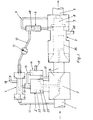
- the apparatus shown schematically in Fig. 1 for protecting erbraucherstellen to V leading drinking water lines against refluxing hot water consists essentially of the built in the drinking water feed line 1 feed valve 2 with an associated pressure-control cylinder 2 ', which the inlet valve 2 downstream tubular separator 3, the pilot cylinder 4, and the holding valve 6 present between the latter and the service water line 5 located behind the pipe separator 3.
- the latter is located in a bypass line 9 located parallel to the outlet connection 7 of the pipe separator 3 and bridging its check valve 8.
- the holding valve 6 is via the pressure control line 10 with a built-in pressure gauge 11 connected to one connection side of the pilot valve 4, the opposite end of which is connected via line 12 to the drinking water supply line 1.
- the connecting line 13 Between the pressure control valve 4 and the pressure control cylinder 2 'there is the connecting line 13, between the latter and a pilot valve 14 the connecting line 15 and between the pressure control cylinder 2', the pilot valve 14 and the water flow area 16 located behind the inlet valve 2, the T-shaped connecting line 17.
- the lines denoted by 18, 19 and 20 are so-called relief lines, which open into the open or into a process not shown in detail.
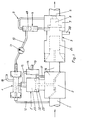
- valve body 2 ′′ belonging to the inlet valve 2 is firmly connected via the piston rod 21 to the pressure control piston 22, which can be displaceably accommodated in the pressure control cylinder 2 ′.
- a valve piston 14' is provided, which acts on is provided at its upper end with a piston membrane 14 ′′ clamped all around in the valve housing and at its lower end with a sealing shoulder 14 ′′.
- the compression spring 14 IV accommodated in the pilot valve 14 tries to hold the piston 14 'in its upper switching position, in which the piston shoulder 14'"blocks the T-shaped connecting line 17 with respect to the relief line 19.
- the piston membrane 14" becomes pressurized accordingly 14 'moved to its lower position, in which the line section 16 and also the lower working chamber 23' are connected to the relief line 19 via the T-shaped connecting line 17.
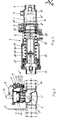
- the valve rod 27 which is fastened in a spoke-like manner in the inlet connection 24, projects sealingly with its valve head 28, which has an annular seal 28 '.
- the piston separating tube 26 is supported on the shoulder 30 of the cylinder 25 via the compression spring 29.
- valve rod 8 ' which is fastened in a spoke-like manner, sits the valve body 8''which forms the actual check valve 8 and is pressed with its end face seal 8''by a comparatively strong compression spring (not shown) against the valve seat surface 8iv in the outlet port 7.
- a comparatively strong compression spring (not shown) against the valve seat surface 8iv in the outlet port 7.
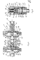
- the pilot valve 4 shown in FIG. 4 has a valve housing 33 which is screwed together from a plurality of molded parts and which is penetrated by a continuous axial bore 34, in which the pilot piston 35 is axially displaceably mounted to a limited extent.
- the piston 35 is provided at both ends with piston flanges 36, 37, which are covered on the outside by piston membranes 38 and 39, the outer circumferences of which are accommodated and clamped in the pressurizing chambers 40 and 41 of the pilot valve 4, which are of correspondingly large diameter.
- the compression spring 42 is accommodated, which acts on the control piston 35 as well as the process water line pressure present via the connecting line 10.
- the left working chamber 40 is connected to the drinking water supply line 1 via the opening line 12.
- the respective inner working chambers 40 'and 41' are connected via ventilation bores 43, 43 'to the outside atmosphere, the bores 43' also ensuring that, even if the piston membrane 39 is damaged, no process water from the line 10 into the central section of the Axial bore 34 can reach, so no otherwise possible contamination of the supply water can take place.
- the pilot piston 35 is 'provided which in the embodiment shown in Fig. 4 flow position of the V or tenukolbens 35 in height of the bore extension 34 ", at its inlet 12 facing end or with its axial bore 35' and a accreting thereto transverse bore 35 in the valve housing 33 . Furthermore, the connections 13 'and 18' for the line 13 leading to the pressure control cylinder 2 'and to the relief line 18 are provided in the valve housing 33. Two ring seals 35 ′′ ′′ are provided on the pilot piston 35 at a corresponding distance from one another and the ring seals 44 are provided in the valve housing in the region of the working chambers 40 ′, 41 ′.
- the holding valve shown in FIG. 5 has a valve housing consisting of the two cylindrical parts 45, 46 screwed together, which is penetrated by a continuous axial bore 47 in which the valve piston 48 is axially displaceably mounted.
- the storage takes place via the ends 48 ′ and 48 ′′ which are tapered in diameter in the correspondingly narrowed end regions 47 ′ and 47 ′′ of the through axial bore 47, which are connected to the bypass line via their lower and upper connection 47 ′′ and 47 IV 9 connected or included in this.
- the valve piston 48 is provided in its central part with a shoulder 48 '', which carries a slightly projecting, flexible flow flange 53 and also serves to support the compression spring. This strives to press the valve piston 48 with its shoulder 48 ''', which carries the sealing ring 55, against the valve seat surface 46' provided on the lower valve housing part 46.
- the shoulder 48 "'and the flexible flow flange 53 are held in diameter so that when water is removed in the service water line 5, the water in the bypass line 9 can flow past the flow flange 53, and then through the transverse bore 48 in the piston 48 to IV and the axial bore continue to flow 48V.
- the compression spring is biased accordingly depending on the prevailing flow water pressure 54, wherein the tubular part 48 'of the valve piston 48 the Z ulaff 47 V to the pilot conduit 10 shut off, as the Fig. 5 shows.
- the inlet valve 2 and its pressure control piston 22 as well as the piston separating pipe 26 and the check valve 8 in the pipe separator 3 assume the closed or disconnected position shown in FIGS. 2 and 3.
- the valve piston 48 of the holding valve 6 rests with its shoulder 48 '''or the sealing ring 55 provided thereon on the valve seat 46', as a result of which the service water line part 5 not only via the check valve 8 in the closed position but also via the bypass line 9 is blocked off from the separation point 32.
- valve piston 48 Since in this locked position the valve piston 48 with its tubular end portion 48 V has connected the connecting line 10 to the bypass line 9 and thus the water pressure prevailing in the service water line 5 together with the pressure spring 42 present in the pilot valve 4, the pilot piston 35 in 4, the pressure control line 12 is connected via the bores 35 'and 35 "and via the bore extension 34" to the line 13' leading to the upper working chamber 23, whereby the pressure control piston 22 in the position shown in FIG 2 position is held.
- the piston 14 ′ present in the pilot valve 14 is also pressed into the lower switching position shown in FIG. 2, in which both the pipe section 16 and the lower working chamber 23 ′ in the pressure control cylinder 2 ′ via the T-shaped line 17 with the relief line 19 stay in contact.
Landscapes
- Health & Medical Sciences (AREA)
- Life Sciences & Earth Sciences (AREA)
- Engineering & Computer Science (AREA)
- Hydrology & Water Resources (AREA)
- Public Health (AREA)
- Water Supply & Treatment (AREA)
- Safety Valves (AREA)
- Rigid Pipes And Flexible Pipes (AREA)
- Devices For Dispensing Beverages (AREA)
Priority Applications (1)
| Application Number | Priority Date | Filing Date | Title |
|---|---|---|---|
| AT85109012T ATE33278T1 (de) | 1984-11-23 | 1985-07-19 | Vorrichtung zum schutz von trinkwasserleitungen. |
Applications Claiming Priority (2)
| Application Number | Priority Date | Filing Date | Title |
|---|---|---|---|
| DE3442748 | 1984-11-23 | ||
| DE19843442748 DE3442748A1 (de) | 1984-11-23 | 1984-11-23 | Vorrichtung zum schutz von trinkwasserleitungen |
Publications (3)
| Publication Number | Publication Date |
|---|---|
| EP0182004A2 true EP0182004A2 (fr) | 1986-05-28 |
| EP0182004A3 EP0182004A3 (en) | 1986-12-17 |
| EP0182004B1 EP0182004B1 (fr) | 1988-03-30 |
Family
ID=6250983
Family Applications (1)
| Application Number | Title | Priority Date | Filing Date |
|---|---|---|---|
| EP85109012A Expired EP0182004B1 (fr) | 1984-11-23 | 1985-07-19 | Dispositif pour protéger des conduites d'eau potable |
Country Status (3)
| Country | Link |
|---|---|
| EP (1) | EP0182004B1 (fr) |
| AT (1) | ATE33278T1 (fr) |
| DE (2) | DE3442748A1 (fr) |
Cited By (3)
| Publication number | Priority date | Publication date | Assignee | Title |
|---|---|---|---|---|
| WO1986007400A1 (fr) * | 1985-06-05 | 1986-12-18 | Grünbeck Wasseraufbereitung GmbH | Sectionneur de tuyau |
| EP0259551A1 (fr) * | 1986-08-08 | 1988-03-16 | Grünbeck Wasseraufbereitung GmbH | Déconnecteur de tuyau comprenant un dispositif de blocage et moyens de contrôle pour le dispositif de blocage |
| EP0278333A3 (en) * | 1987-02-06 | 1990-03-07 | Schubert & Salzer Maschinenfabrik Aktiengesellschaft | Control device for a pipe separator |
Families Citing this family (1)
| Publication number | Priority date | Publication date | Assignee | Title |
|---|---|---|---|---|
| ATE53878T1 (de) * | 1987-08-31 | 1990-06-15 | Honeywell Braukmann Gmbh | Trinkwasser-durchflussarmatur. |
Family Cites Families (3)
| Publication number | Priority date | Publication date | Assignee | Title |
|---|---|---|---|---|
| US3276465A (en) * | 1963-01-18 | 1966-10-04 | Donald G Griswold | Backflow prevention device and relief valve control |
| DE2806310C2 (de) * | 1978-02-15 | 1986-08-21 | Lang Apparatebau GmbH, 8227 Siegsdorf | Vorrichtung zum Schutz von Trinkwasserleitungen gegen rückfließendes Brauchwasser |
| DE2849825C2 (de) * | 1978-11-17 | 1984-05-10 | Lang Apparatebau GmbH, 8227 Siegsdorf | Trinkwasser-Durchflußarmatur mit in eine Trinkwasserversorgungsleitung eingebautem Durchflußwächter |
-
1984
- 1984-11-23 DE DE19843442748 patent/DE3442748A1/de not_active Withdrawn
-
1985
- 1985-07-19 DE DE8585109012T patent/DE3562030D1/de not_active Expired
- 1985-07-19 EP EP85109012A patent/EP0182004B1/fr not_active Expired
- 1985-07-19 AT AT85109012T patent/ATE33278T1/de not_active IP Right Cessation
Cited By (4)
| Publication number | Priority date | Publication date | Assignee | Title |
|---|---|---|---|---|
| WO1986007400A1 (fr) * | 1985-06-05 | 1986-12-18 | Grünbeck Wasseraufbereitung GmbH | Sectionneur de tuyau |
| US4745946A (en) * | 1985-06-05 | 1988-05-24 | Kern Johann H | Pipe separator |
| EP0259551A1 (fr) * | 1986-08-08 | 1988-03-16 | Grünbeck Wasseraufbereitung GmbH | Déconnecteur de tuyau comprenant un dispositif de blocage et moyens de contrôle pour le dispositif de blocage |
| EP0278333A3 (en) * | 1987-02-06 | 1990-03-07 | Schubert & Salzer Maschinenfabrik Aktiengesellschaft | Control device for a pipe separator |
Also Published As
| Publication number | Publication date |
|---|---|
| EP0182004A3 (en) | 1986-12-17 |
| ATE33278T1 (de) | 1988-04-15 |
| EP0182004B1 (fr) | 1988-03-30 |
| DE3562030D1 (en) | 1988-05-05 |
| DE3442748A1 (de) | 1986-05-28 |
Similar Documents
| Publication | Publication Date | Title |
|---|---|---|
| DE69216341T2 (de) | Filtereinheit | |
| DE69731558T2 (de) | Medizinische vorrichtung zum injizieren von flüssigkeiten | |
| EP0329919B1 (fr) | Dispositif pour éliminer des huiles dans un courant de gaz comprimé | |
| DE2711974A1 (de) | Rueckstrom-sperre mit sicherheits- absperrorgan | |
| EP0088861B1 (fr) | Soupape anti-retour spécialement pour des conduites d'eau potable | |
| DE102005031422C5 (de) | Systemtrenner | |
| CH628383A5 (de) | Vorrichtung zum schutz von trinkwasserleitungen gegen rueckfliessendes brauchwasser. | |
| DE3323324A1 (de) | Verfahren und vorrichtung zum anpassen des ansprechdruckes an die in der abflussleitung gegebenen druckverhaeltnisse bei einer einrichtung zum verhindern des rueckflusses eines mediums in die zuflussleitung | |
| EP0182004B1 (fr) | Dispositif pour protéger des conduites d'eau potable | |
| DE3341643A1 (de) | Vorgesteuertes druckentlastungs- und steuerventil | |
| DE2747941C2 (de) | Vorrichtung zum Schutz von Trinkwasserleitungen gegen rückfließendes Brauchwasser | |
| DE2806310C2 (de) | Vorrichtung zum Schutz von Trinkwasserleitungen gegen rückfließendes Brauchwasser | |
| DE648910C (de) | Kreiselpumpenanlage | |
| EP0183909B1 (fr) | Déconnecteur de tuyaux, en particulier pour conduites d'eau potable | |
| DE3121103C2 (de) | Membranpumpe | |
| DE2759703C2 (fr) | ||
| DE2729305A1 (de) | Rohrtrenner | |
| DE3742207A1 (de) | Rueckflussverhinderer, insbesondere zum einbau in trinkwasserleitungen | |
| DE3347805C2 (de) | Vorrichtung zum Anpassen des Ansprechdruckes an die in der Abflußleitung gegebenen Druckverhältnisse bei einer Einrichtung zum Verhindern des Rückflusses eines Mediums aus einer Abflußleitung zurück in die Zuflußleitung | |
| DE3019987C2 (de) | Wirkdruckzumischgerät | |
| DE8434344U1 (de) | Vorrichtung zum Schutz von Trinkwasserleitungen | |
| DE2107647A1 (de) | Vorrichtung zum Verhindern des Nachtropfens bei einer Abfüllanlage | |
| EP0064048A1 (fr) | Vanne de régulation, en particulier vanne de mélange ou de dosage | |
| AT340731B (de) | Selbstschliessendes sicherheitsventil fur wasserleitungsbruch | |
| DE268059C (fr) |
Legal Events
| Date | Code | Title | Description |
|---|---|---|---|
| PUAI | Public reference made under article 153(3) epc to a published international application that has entered the european phase |
Free format text: ORIGINAL CODE: 0009012 |
|
| AK | Designated contracting states |
Kind code of ref document: A2 Designated state(s): AT BE CH DE FR IT LI LU NL |
|
| PUAL | Search report despatched |
Free format text: ORIGINAL CODE: 0009013 |
|
| AK | Designated contracting states |
Kind code of ref document: A3 Designated state(s): AT BE CH DE FR IT LI LU NL |
|
| 17P | Request for examination filed |
Effective date: 19861106 |
|
| 17Q | First examination report despatched |
Effective date: 19870811 |
|
| GRAA | (expected) grant |
Free format text: ORIGINAL CODE: 0009210 |
|
| AK | Designated contracting states |
Kind code of ref document: B1 Designated state(s): AT BE CH DE FR IT LI NL |
|
| REF | Corresponds to: |
Ref document number: 33278 Country of ref document: AT Date of ref document: 19880415 Kind code of ref document: T |
|
| REF | Corresponds to: |
Ref document number: 3562030 Country of ref document: DE Date of ref document: 19880505 |
|
| ITF | It: translation for a ep patent filed | ||
| ET | Fr: translation filed | ||
| PLBE | No opposition filed within time limit |
Free format text: ORIGINAL CODE: 0009261 |
|
| STAA | Information on the status of an ep patent application or granted ep patent |
Free format text: STATUS: NO OPPOSITION FILED WITHIN TIME LIMIT |
|
| 26N | No opposition filed | ||
| PGFP | Annual fee paid to national office [announced via postgrant information from national office to epo] |
Ref country code: FR Payment date: 19900717 Year of fee payment: 6 |
|
| ITTA | It: last paid annual fee | ||
| PGFP | Annual fee paid to national office [announced via postgrant information from national office to epo] |
Ref country code: NL Payment date: 19900731 Year of fee payment: 6 |
|
| PGFP | Annual fee paid to national office [announced via postgrant information from national office to epo] |
Ref country code: BE Payment date: 19900808 Year of fee payment: 6 |
|
| REG | Reference to a national code |
Ref country code: CH Ref legal event code: PUE Owner name: WALETZKO ARMATUREN GMBH |
|
| PG25 | Lapsed in a contracting state [announced via postgrant information from national office to epo] |
Ref country code: BE Effective date: 19910731 |
|
| NLS | Nl: assignments of ep-patents |
Owner name: WALETZKO ARMATUREN GMBH TE GEVELSBERG, BONDSREPUBL |
|
| BERE | Be: lapsed |
Owner name: WALETZKO ARMATUREN G.M.B.H. Effective date: 19910731 |
|
| PG25 | Lapsed in a contracting state [announced via postgrant information from national office to epo] |
Ref country code: NL Effective date: 19920201 |
|
| NLV4 | Nl: lapsed or anulled due to non-payment of the annual fee | ||
| PG25 | Lapsed in a contracting state [announced via postgrant information from national office to epo] |
Ref country code: FR Effective date: 19920331 |
|
| REG | Reference to a national code |
Ref country code: FR Ref legal event code: ST |
|
| PGFP | Annual fee paid to national office [announced via postgrant information from national office to epo] |
Ref country code: AT Payment date: 19920715 Year of fee payment: 8 |
|
| PGFP | Annual fee paid to national office [announced via postgrant information from national office to epo] |
Ref country code: CH Payment date: 19920716 Year of fee payment: 8 |
|
| PGFP | Annual fee paid to national office [announced via postgrant information from national office to epo] |
Ref country code: DE Payment date: 19920727 Year of fee payment: 8 |
|
| PG25 | Lapsed in a contracting state [announced via postgrant information from national office to epo] |
Ref country code: AT Effective date: 19930719 |
|
| PG25 | Lapsed in a contracting state [announced via postgrant information from national office to epo] |
Ref country code: LI Effective date: 19930731 Ref country code: CH Effective date: 19930731 |
|
| REG | Reference to a national code |
Ref country code: CH Ref legal event code: PL |
|
| PG25 | Lapsed in a contracting state [announced via postgrant information from national office to epo] |
Ref country code: DE Effective date: 19940401 |