EP0182012A2 - Dispositif pour réaliser une épissure de conducteur - Google Patents
Dispositif pour réaliser une épissure de conducteur Download PDFInfo
- Publication number
- EP0182012A2 EP0182012A2 EP85110494A EP85110494A EP0182012A2 EP 0182012 A2 EP0182012 A2 EP 0182012A2 EP 85110494 A EP85110494 A EP 85110494A EP 85110494 A EP85110494 A EP 85110494A EP 0182012 A2 EP0182012 A2 EP 0182012A2
- Authority
- EP
- European Patent Office
- Prior art keywords
- channels
- housing
- cutting
- wires
- wire
- Prior art date
- Legal status (The legal status is an assumption and is not a legal conclusion. Google has not performed a legal analysis and makes no representation as to the accuracy of the status listed.)
- Granted
Links
Images
Classifications
-
- H—ELECTRICITY
- H01—ELECTRIC ELEMENTS
- H01R—ELECTRICALLY-CONDUCTIVE CONNECTIONS; STRUCTURAL ASSOCIATIONS OF A PLURALITY OF MUTUALLY-INSULATED ELECTRICAL CONNECTING ELEMENTS; COUPLING DEVICES; CURRENT COLLECTORS
- H01R4/00—Electrically-conductive connections between two or more conductive members in direct contact, i.e. touching one another; Means for effecting or maintaining such contact; Electrically-conductive connections having two or more spaced connecting locations for conductors and using contact members penetrating insulation
- H01R4/24—Connections using contact members penetrating or cutting insulation or cable strands
- H01R4/2416—Connections using contact members penetrating or cutting insulation or cable strands the contact members having insulation-cutting edges, e.g. of tuning fork type
- H01R4/242—Connections using contact members penetrating or cutting insulation or cable strands the contact members having insulation-cutting edges, e.g. of tuning fork type the contact members being plates having a single slot
- H01R4/2425—Flat plates, e.g. multi-layered flat plates
- H01R4/2429—Flat plates, e.g. multi-layered flat plates mounted in an insulating base
-
- H—ELECTRICITY
- H01—ELECTRIC ELEMENTS
- H01R—ELECTRICALLY-CONDUCTIVE CONNECTIONS; STRUCTURAL ASSOCIATIONS OF A PLURALITY OF MUTUALLY-INSULATED ELECTRICAL CONNECTING ELEMENTS; COUPLING DEVICES; CURRENT COLLECTORS
- H01R4/00—Electrically-conductive connections between two or more conductive members in direct contact, i.e. touching one another; Means for effecting or maintaining such contact; Electrically-conductive connections having two or more spaced connecting locations for conductors and using contact members penetrating insulation
- H01R4/24—Connections using contact members penetrating or cutting insulation or cable strands
- H01R4/2416—Connections using contact members penetrating or cutting insulation or cable strands the contact members having insulation-cutting edges, e.g. of tuning fork type
- H01R4/2445—Connections using contact members penetrating or cutting insulation or cable strands the contact members having insulation-cutting edges, e.g. of tuning fork type the contact members having additional means acting on the insulation or the wire, e.g. additional insulation penetrating means, strain relief means or wire cutting knives
- H01R4/245—Connections using contact members penetrating or cutting insulation or cable strands the contact members having insulation-cutting edges, e.g. of tuning fork type the contact members having additional means acting on the insulation or the wire, e.g. additional insulation penetrating means, strain relief means or wire cutting knives the additional means having two or more slotted flat portions
Definitions
- the invention is directed to a device for testing a wire splice, in particular wires of telephone cables, with an element electrically connecting the conductors of the individual wires and a sheath surrounding the connecting point.
- wire connecting sleeves are known as simple connecting means, which consist of an inner contact part with inwardly projecting tips for penetrating the conductor insulation, a pressure part for easier deformability and an outer insulating part, e.g. a plastic sleeve.
- the ends of cable wires to be connected are inserted into these known wire connecting sleeves, the connecting sleeve is then pressed with a tool, so that the inner contact part penetrates the insulation of the inserted two cable ends and connects the conductors to one another in an electrically conductive manner.
- wire connection strips are also known, which are equipped with comb-like cutting / clamping elements, into which the cable wires to be connected are inserted and by pressing the housing parts, these strips are both electrically conductive which can also be shortened (for example DF-GM 82 20 212 by the applicant).
- the object of the invention is to provide a solution with which an uninterrupted splicing in operation is possible, in particular for pairs of wires, the device for remaining in the final splice being just as suitable as is the case with the cable core connecting sleeves.
- this object is achieved according to the invention in that the sheath or the housing is provided with at least two channels which allow the passage of wires, the channels having a common electrically conductive cutting / clamping element for stripping-free electrically conductive Connection of the cable wires inserted in the channels are provided.
- a continuous wire is first inserted into a channel of the device while the wire to be spliced is inserted into the other channel.
- the wire is designedsplskyende interruption of the connected to the passing through A.
- the trailing wire can then be removed in its omitted part without an interruption taking place during operation.
- the invention provides that the two channels are arranged essentially at right angles to one another within the device, in which case the cutting / clamping element is also expediently designed at right angles.
- the invention also provides that, in addition to the two through-channels, at least one channel parallel to one of the channels and ending in the device for blunt insertion of a free end of a wire is provided, the cutting / clamping element also being arranged to engage in this channel in some areas.
- the invention also provides that guides for the engagement of cutting knives are provided perpendicular to the channels in the through-quan regions of the cable cores.
- cutting knives are inserted in the guides arranged perpendicular to the channels, which then cut off both the old wire and the loop-forming area of the A to be spliced in without the electrical line being interrupted during the entire process.
- the invention also provides that the cutting knives are arranged in a separate component.
- This separate member may be arranged for example on a printing plate of a Zan- g e.
- the housing and the end cover are each equipped with corresponding elements of a snap connection, for. B. can be provided on the edge of the housing grooves, which are overlapped by corresponding locking beads inside the cover.
- the device In order to simplify assembly - the device is a comparatively very small component in many applications - the invention also provides that the housing with engagement grooves for engaging a pressing tool to carry out the engagement movement of the cutting / clamping element and / or the cutting knife and / or snap connection between cover and housing is equipped.
- a locking device is provided for temporarily holding the inserted cable core.
- This locking device can be formed, for example, by corresponding tabs in the insertion opening, or else by a molded-in clamping hook behind which the inserted wire can be clamped.
- the housing is equipped on at least one side with a receiving bore and on the opposite side of this receiving bore with a ratchet pin for engaging in the receiving bore of an adjacent housing, so that a lot number of devices in the splice can be plugged together into strips.
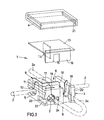
- the device generally designated 1 in the figures for producing a wire splice, ie for the electrically conductive connection of an initially continuous A of FIG. 2 to a wire 2a to be spliced, in the example shown consists of an essentially rectangular housing 3 with a housing cover 4.
- the housing 3 has two channels 5 at right angles to one another for the wire 2 and 6 for the wire 2a and an additional channel 7 which ends in the housing 3 and runs parallel to the channel 6 and into which the free end (designated 8 in FIG. 1) the wire 2a can be inserted.
- a cutting / clamping element 9 engages, which is equipped with contact cutting edges for penetrating the insulation of the wires 2 and 2a.
- the contact point for the initially continuous wire 2 is designated 10.
- the contact point for the free end 8 of the wire 2a with 11 and the second contact point for the wire 2a after return and insertion into the channel 6 is finally designated 12.
- 3 guide slots are provided in the housing for cutting knives 14, 15 and 16 shown on a separate carrier plate 13 in FIG. 1, these guide slots being designated 17, 18 and 19. These guide slots 17-19 are arranged perpendicular to the channels 5, 6 and 7.
- the support element 13 for the cutting knives 14-16 can, for example, be the claw of a pair of pliers (not shown in more detail) or an integral part of the cover 4, so that the cutting movement is exerted on the housing 3 when the cover 4 is pressed on.
- a snap connection between the housing 3 and cover 4 is provided, which in the example shown are composed of locking grooves 20 in the housing 3 and locking cams 21 in the cover 4.
- the housing 3 also has finger grooves 22 to engage a press tool, not shown.
- the pliers which can be equipped with the cutting blades, can also be designed in a fork-like manner in order to be able to engage in these grooves 22.
- both the contacting that is to say the pressing in of the cutting / clamping element 9, and the subsequent separation of the free end 8 or the part of the continuous cable core 2 which is no longer required by inserting the cutting knives can then take place in one work step 14 - 16 into the grooves 17 - 19 and then pressing on the cover 4.
- a lock 23 is at the channel 7 is provided, which there consists of plastic blades, which holds in this channel, this free E n-de therein after insertion of the free end 8, without the invention to this special form of locking would be limited.
- At least a receiving bore 24 is provided on the housing 3 for receiving a ratchet pin 25 of an adjacent housing 3 so that the devices can be fixed to one another line by line.
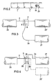
- This plug connection results in particular in connection with FIG. 2.
- the wire 2a to be spliced is placed in a loop and is returned through the housing 3, as shown in FIG. 4, through the continuous channel 6 running parallel to channel 7. Clamping element 9 pressed from above that an electrically conductive connection is made. In this state, the wire 2 a is double electrically connected to the wire 2 that is still continuous.
- the continuous core 2 has an interface 28, while the loop of the core 2a is separated, ie shortened, by two interfaces 29 and 30.
- the electrically conductive connection is always maintained throughout the entire process.
- the described embodiment of the invention can be modified in many ways without departing from the basic idea.
- the invention is not limited to the special spatial arrangement of the channels in the device.
- Other angular parallelism or the like can also be provided here. This also applies to the design of the cutting / contact element as well as the separating knife 14-16 and / or the connection cover / housing.
Landscapes
- Connections By Means Of Piercing Elements, Nuts, Or Screws (AREA)
- Multi-Conductor Connections (AREA)
Applications Claiming Priority (2)
| Application Number | Priority Date | Filing Date | Title |
|---|---|---|---|
| DE8433159U | 1984-11-13 | ||
| DE8433159U DE8433159U1 (de) | 1984-11-13 | 1984-11-13 | Vorrichtung zur Erzeugung eines Aderspleißes |
Publications (3)
| Publication Number | Publication Date |
|---|---|
| EP0182012A2 true EP0182012A2 (fr) | 1986-05-28 |
| EP0182012A3 EP0182012A3 (en) | 1989-03-15 |
| EP0182012B1 EP0182012B1 (fr) | 1990-06-20 |
Family
ID=6772638
Family Applications (1)
| Application Number | Title | Priority Date | Filing Date |
|---|---|---|---|
| EP85110494A Expired - Lifetime EP0182012B1 (fr) | 1984-11-13 | 1985-08-21 | Dispositif pour réaliser une épissure de conducteur |
Country Status (4)
| Country | Link |
|---|---|
| US (1) | US4725247A (fr) |
| EP (1) | EP0182012B1 (fr) |
| DE (2) | DE8433159U1 (fr) |
| ES (1) | ES8702087A1 (fr) |
Cited By (1)
| Publication number | Priority date | Publication date | Assignee | Title |
|---|---|---|---|---|
| EP0382482A3 (fr) * | 1989-02-06 | 1991-02-27 | Molex Incorporated | Connecteur de câble électrique à plusieurs conducteurs |
Families Citing this family (6)
| Publication number | Priority date | Publication date | Assignee | Title |
|---|---|---|---|---|
| US5586905A (en) * | 1993-11-01 | 1996-12-24 | Molex Incorporated | Insulation displacement electrical connector with improved strain relief |
| EP0698950B1 (fr) * | 1994-08-23 | 2001-06-13 | Sumitomo Wiring Systems, Ltd. | Construction de câblage d'une boíte de raccordement électrique |
| JPH08162177A (ja) * | 1994-12-05 | 1996-06-21 | Yazaki Corp | 圧接コネクタへの電線圧接方法及び圧接コネクタ |
| FR2819977B1 (fr) * | 2001-01-23 | 2003-04-11 | Sofanou Sa | Piece de support et de fixation d'un composant electrique |
| US7186132B2 (en) | 2005-05-31 | 2007-03-06 | Raul Quintanilla | Electrical and electronic connector with blade closed by lever |
| JP7265458B2 (ja) * | 2019-09-26 | 2023-04-26 | 日本航空電子工業株式会社 | コネクタおよび接続方法 |
Family Cites Families (12)
| Publication number | Priority date | Publication date | Assignee | Title |
|---|---|---|---|---|
| US1290153A (en) * | 1918-03-30 | 1919-01-07 | Joseph Fitzpatrick | Wire-tapper. |
| US1488636A (en) * | 1920-05-24 | 1924-04-01 | Geiser John Albert | Wire connecter |
| US2469397A (en) * | 1945-11-14 | 1949-05-10 | Melvin E Mezek | Electrical connector |
| US2928066A (en) * | 1956-11-28 | 1960-03-08 | Gordon James | Electrical terminal block |
| NL249266A (fr) * | 1959-03-19 | |||
| US3718888A (en) * | 1971-01-04 | 1973-02-27 | Bell Telephone Labor Inc | Universal connector for cable conductors |
| CA1001250A (en) * | 1973-02-02 | 1976-12-07 | Thomas J. Antolak | Solderless electrical contact element assembly, receptacle and applicator |
| NL155989B (nl) * | 1973-12-19 | 1978-02-15 | Amp Inc | Elektrisch verbindingsorgaan met isolatiedoorsnijgleuven. |
| US4326767A (en) * | 1979-03-12 | 1982-04-27 | Minnesota Mining And Manufacturing Company | Wire cutting electrical connector |
| US4232927A (en) * | 1979-03-16 | 1980-11-11 | E. I. Du Pont De Nemours And Company | Electrical connector |
| US4364622A (en) * | 1980-05-09 | 1982-12-21 | Minnesota Mining And Manufacturing Company | Connector for flat cable |
| US4441779A (en) * | 1980-12-31 | 1984-04-10 | E. I. Du Pont De Nemours & Company | Contact device for a multiconductor cable |
-
1984
- 1984-11-13 DE DE8433159U patent/DE8433159U1/de not_active Expired
-
1985
- 1985-08-21 DE DE8585110494T patent/DE3578365D1/de not_active Expired - Fee Related
- 1985-08-21 EP EP85110494A patent/EP0182012B1/fr not_active Expired - Lifetime
- 1985-09-05 ES ES546732A patent/ES8702087A1/es not_active Expired
-
1987
- 1987-06-08 US US07/059,234 patent/US4725247A/en not_active Expired - Fee Related
Cited By (1)
| Publication number | Priority date | Publication date | Assignee | Title |
|---|---|---|---|---|
| EP0382482A3 (fr) * | 1989-02-06 | 1991-02-27 | Molex Incorporated | Connecteur de câble électrique à plusieurs conducteurs |
Also Published As
| Publication number | Publication date |
|---|---|
| DE3578365D1 (de) | 1990-07-26 |
| EP0182012A3 (en) | 1989-03-15 |
| ES8702087A1 (es) | 1986-12-01 |
| US4725247A (en) | 1988-02-16 |
| DE8433159U1 (de) | 1985-02-07 |
| ES546732A0 (es) | 1986-12-01 |
| EP0182012B1 (fr) | 1990-06-20 |
Similar Documents
| Publication | Publication Date | Title |
|---|---|---|
| EP0196495B1 (fr) | Pince | |
| DE10250933B3 (de) | Verbinderanordnung zwischen einem Flex-Flachbandkabel und einer elektrischen Leiterplatte | |
| DE3711675C2 (fr) | ||
| DE69604331T2 (de) | Verbindermodul mit Zugang zu Test- und Anschlusszwecken | |
| DE4437022C1 (de) | Anschlußelement | |
| EP0244347B1 (fr) | Réglette de connexion pour fils de câbles, particulièrement de câbles téléphoniques | |
| DE69417306T2 (de) | Trennbarer steckverbinder für kommunikationsnetz | |
| DE69735924T2 (de) | Verfahren zur Herstellung für Telefon- oder Datenreihenklemmen und nach diesem Verfahren erhaltene Reihenklemme | |
| EP0062771A1 (fr) | Connexion de conducteurs d'un câble de télécommunication | |
| WO2003021721A1 (fr) | Raccord de cables | |
| DE69710548T2 (de) | Verbinderanordnung für die Statorwicklungen eines elektrischen Motors | |
| DE19838423A1 (de) | Flachbandkabelverbinder | |
| DE19854200A1 (de) | Vorrichtung zum Kontaktieren einer elektrischen Leitung, insbesondere einer Flachbandleitung | |
| DE69019187T2 (de) | Elektrischer Mehrleiterkabelverbinder. | |
| DE7303044U (de) | AnschluBkasten | |
| EP0182012B1 (fr) | Dispositif pour réaliser une épissure de conducteur | |
| DE102010034790A1 (de) | Vorrichtung und Verfahren zur Kontaktierung eines elektrischen Leiters mit einer Leiterbahn und Kontaktträger für eine solche Vorrichtung | |
| DE19751699C2 (de) | Vorrichtung zum Verbinden von Kabeladern | |
| EP1158611A2 (fr) | Connecteur de câble | |
| CH687113A5 (de) | Leiteranschlussvorrichtung fuer Schwachstromanlagen. | |
| DE19903030C1 (de) | Vorrichtung zur abisolierfreien Kontaktierung eines Flachkabels | |
| DE69326458T2 (de) | Verbindervorrichtung für elektrische Bauteile | |
| DE3024643A1 (de) | Flaches elektrisches mehrleiter-verbindungssystem | |
| DE4320539A1 (de) | Leitungsdraht-Verbindungsklemme | |
| EP0852080B1 (fr) | Procede de mise en contact d'un connecteur multipolaire a ressort |
Legal Events
| Date | Code | Title | Description |
|---|---|---|---|
| PUAI | Public reference made under article 153(3) epc to a published international application that has entered the european phase |
Free format text: ORIGINAL CODE: 0009012 |
|
| AK | Designated contracting states |
Kind code of ref document: A2 Designated state(s): DE FR GB IT SE |
|
| PUAL | Search report despatched |
Free format text: ORIGINAL CODE: 0009013 |
|
| AK | Designated contracting states |
Kind code of ref document: A3 Designated state(s): DE FR GB IT SE |
|
| 17P | Request for examination filed |
Effective date: 19890206 |
|
| 17Q | First examination report despatched |
Effective date: 19890728 |
|
| GRAA | (expected) grant |
Free format text: ORIGINAL CODE: 0009210 |
|
| AK | Designated contracting states |
Kind code of ref document: B1 Designated state(s): DE FR GB IT SE |
|
| REF | Corresponds to: |
Ref document number: 3578365 Country of ref document: DE Date of ref document: 19900726 |
|
| GBT | Gb: translation of ep patent filed (gb section 77(6)(a)/1977) | ||
| ITF | It: translation for a ep patent filed | ||
| ET | Fr: translation filed | ||
| PLBE | No opposition filed within time limit |
Free format text: ORIGINAL CODE: 0009261 |
|
| STAA | Information on the status of an ep patent application or granted ep patent |
Free format text: STATUS: NO OPPOSITION FILED WITHIN TIME LIMIT |
|
| 26N | No opposition filed | ||
| ITTA | It: last paid annual fee | ||
| PGFP | Annual fee paid to national office [announced via postgrant information from national office to epo] |
Ref country code: SE Payment date: 19930802 Year of fee payment: 9 |
|
| PGFP | Annual fee paid to national office [announced via postgrant information from national office to epo] |
Ref country code: GB Payment date: 19930803 Year of fee payment: 9 |
|
| PGFP | Annual fee paid to national office [announced via postgrant information from national office to epo] |
Ref country code: FR Payment date: 19930813 Year of fee payment: 9 |
|
| PG25 | Lapsed in a contracting state [announced via postgrant information from national office to epo] |
Ref country code: GB Effective date: 19940821 |
|
| PG25 | Lapsed in a contracting state [announced via postgrant information from national office to epo] |
Ref country code: SE Effective date: 19940822 |
|
| EAL | Se: european patent in force in sweden |
Ref document number: 85110494.3 |
|
| GBPC | Gb: european patent ceased through non-payment of renewal fee |
Effective date: 19940821 |
|
| PG25 | Lapsed in a contracting state [announced via postgrant information from national office to epo] |
Ref country code: FR Effective date: 19950428 |
|
| EUG | Se: european patent has lapsed |
Ref document number: 85110494.3 |
|
| REG | Reference to a national code |
Ref country code: FR Ref legal event code: ST |
|
| PGFP | Annual fee paid to national office [announced via postgrant information from national office to epo] |
Ref country code: DE Payment date: 19980827 Year of fee payment: 14 |
|
| PG25 | Lapsed in a contracting state [announced via postgrant information from national office to epo] |
Ref country code: DE Free format text: LAPSE BECAUSE OF NON-PAYMENT OF DUE FEES Effective date: 20000601 |